


Conrad Preen
-
Posts
1,023 -
Joined
-
Last visited
Content Type
Profiles
Forums
Events
Articles
Marionette
Store
Posts posted by Conrad Preen
-
-
Hi Ross
We'll keep that in mind but it's probably worth re-posting it here https://forum.vectorworks.net/index.php?/forum/19-wishlist-feature-and-content-requests/
since it's more of a general request than specific to ConnectCAD
Conrad
-
Guess that's something we could think about. Meanwhile it's quite easy to work around. While you've got your devices selected just type in the new prefix with a space at the end and then renumber.
Conrad
-
Sounds like a job for a scripter...
-
Hi Ross
No it doesn't change the Equipment name. I can see your point, but I can also see potential snags. More than one schematic device can point to a particular Equipment Item. So at the moment it would be tricky to make this automatic. I'll think about it though and maybe I'll find a way.
Conrad
-
 1
1
-
-
Hi James
ANSI TIA 606-B is an interesting one. The challenge is that it stipulates a different cable number at either end of the cable. I guess that is handy for inter-area cables but for cabling within the same room it adds an extra wrinkle to installation. But since it is a standard I will put it on the map to support it.
Luck to us!
Conrad
-
1
-
-
Hi Ross,
This command simply renumbers selected sockets or devices. The command does not guarantee or check for unique device names. You should use Check Drawing for that. Remember device names don't have to be unique but socket names with a given devices should be unique. Check Drawing tests for this.
Renumber Devices / Sockets can
- either apply a numeric suffix to each selected item e.g. 1,2,3,4,
- or apply and alphabetic suffix with a delimiter character e.g. _a, _b, _c etc.
- existing suffixes of the chosen type are stripped off prior to renumbering
- you can choose start value, increment, format etc. so you can have 3,5,7,9 or d,g,j,m and so on...
- you can choose the order of numbering left-to-right, to-to-bottom stacking order etc.
The suffix is applied to each device in the selection and incremented as we go. The parameters that get updated are Name and Display Tag.
If you experiment a bit you will discover lots of ways to use this command.
Hope I've helped a bit
Conrad
-
-
Hi Ross
Yes that's a nice idea. I have implemented something similar - a "Google it" button that we use internally which searches for <make> + <model>. The only problem that I can see with your suggestion is that the internet is a very dynamic place and things move around a lot. I suspect that it would keep someone extremely busy just checking and updating all the URLs. We are quite a small team taking care of ConnectCAD, we just manage to create the illusion that there are a lot of us by moving around very fast🤣 🤣🤣.
Conrad
-
 1
1
-
-
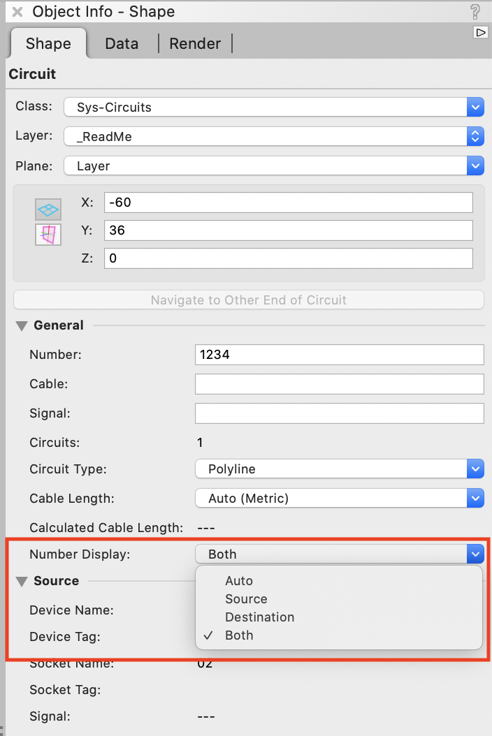
We have added options in the Circuit object info palette to let you override the logic.
Best
Conrad

-
Update Rack Elevation is due for a face lift so I will enter the "Selected devices only" option as a wish item. This is really easy and will help a lot.
Presetting locations of devices is another can of worms altogether as you saw from my brief introduction. There are an awful lot of assumptions that have to hold true for that to work. Simple straightforward solutions are the way to go.
Thanks very much for bringing this up!
Conrad
-
Hi Ross
Yes it makes sense. But it isn't a complete workflow yet. Let's say for the sake of argument we made the Device location fields editable. Now what?
What will be the behaviour when you create Equipment items? If the room exists shall we put the Equipment in it? and where? starting top-left and moving across perhaps? If the equipment is too much for the size of the room then shall we make the room bigger? and if it overlaps another room? If the room doesn't exist do we create it? and where?
Complicated...
Here's my 2c worth. The problem is that all the equipment arrives at once - like a bad removal firm! What if the command that creates the equipment had an option "Selected devices only"? Then you could select the devices in a particular room, create equipment and place it in the room on the layout drawing. Repeat until all rooms are done.
That's an easy one to do. What do you think?
Conrad
-
2
-
-
More flexibility in how you can label arrow connections is very much on our roadmap.
Conrad
-
@livespace josha I love this kind of ingenuity! The combination of Spaces and Circuits hasn't been evaluated by our team but it certainly is interesting. Yes Circuits have a path regardless of the drawing style you choose. So there will be limitations as a result. Definitely food for thought. As you know we listen to what you say and this feeds into new features. Thanks !!!
Conrad
-
That's exactly it Eliot. The Circuit object effectively implements a database JOIN because at the moment the Vectorworks internal database doesn't support this. Goes without saying that this is something I want to change.
Another problem that I see is that this forum contains loads of information but no way to access it! So we end up answering the same questions over and over. @hihosilvey it's not your fault the forum is deficient.
Conrad
-
1
-
-
Hi Thomas
Well I just did a test and if I first de-number all the cables then both incrementing and generated sequences start from 1. Using Number Cables... that is.
Conrad
-
I've already said all that I can at this point.
-
Well I'm not an expert on Spotlight - it was just a suggestion. Let me see where our numbering basis is stored.
-
About the other request. The permutations of what customer may ask are limitless and we can only cater for the more likely ones. You can automate anything in Vectorworks / ConnectCAD using Vectorscript, Python or Marionette.
Conrad
-
Hi Thomas
Maybe the Spotlight Numbering command would be a good friend to you here? Jim Woodward has put a guide to this in the Did You Know thread.
Conrad
-
@Eliot Hartzler You have a bright future as a technical author !!!
Really appreciate the contribution
Conrad
-
As you know the ConnectCAD team listen very carefully. And we are moving forwards with all these matters. The input you give here is very very much appreciated. And the time you take to create pictures illustrating these points is well worth it.
It's the enthusiasm of this community that keeps me and my team working to make ConnectCAD the best.
Thank you all!
Conrad
-
1
-
-
@hihosilvey First of all, constructive comment like yours never causes offence. On the contrary these kind of explorations are what help us keep ConnectCAD out there in front of the rest. And that's why I don't like to force people into a particular workflow. That feels like the tail wagging the dog. In my view the software should support the process you find most natural.
We already have plans well advanced to facilitate greater customization of arrow labels. Moving whole chunks of schematic including arrow connections between layers is a technical challenge. We will definitely look into it. But I come back to the fact that the main driver for this need is the labeling of arrows on paper printouts. The old naming paradigm of <layer> <device> <socket> is in any case somewhat dated because now an arrow can appear in a viewport on any sheet layer. That's what needs to be improved. Even a simple reference code like 'A', 'B', 'C' would do fine for navigating no paper.
"Customise length and direction of arrows on both sides." Basically the problem is the lack of a control handle at the destination end. It would have to be visible and active when the destination layer is visible and active. And we don't have that facility yet. I'm aware of the issue and if we can fix it we will.
Conrad
-
That is the Vectorworks object name. You can use this as part of Criteria for selections and reports. ConnectCAD doesn't make any use of this any more.
Conrad
-
1
-
-
Hi @hihosilvey
I've had a play with your workflow moving selected devices and circuits between layers. You were leveraging the older implementation of arrow circuits to the full. Back in the day the destination arrow was a separate object. The horribly-named Reverse Arrow. Keeping these in sync with their Circuits was a veritable nightmare with a zillion ways to go wrong. But one thing it was better at was being moved to another layer.
We re-implemented the arrow Circuit to do it all in one object that can display on more one layer. This is better in so may other respects that I lose count. But changing the layer will need arrow circuits to be re-drawn and polyline circuits to be nudged so they reset after the devices have arrived on the new layer.
The actual reason for your working this way in fact has to do with the labels. So here's my question: if you had more flexibility in labeling the arrow ends would you still need to move stuff between design layers? So in your dream CAD system how would your arrow labels be?
Conrad
ConnectCAD - Device URL to manufacturer website/datasheet
in Wishlist - Feature and Content Requests
Posted
I've got to admit you have me worried, Ross. If ConnectCAD seems like such a mountain then I would really like to know where you are getting stuck so I can "flatten the curve" as it were...
Conrad