arquitextonica
-
Posts
70 -
Joined
-
Last visited
Content Type
Profiles
Forums
Events
Articles
Marionette
Store
Everything posted by arquitextonica
-
Completely agree. In fact the thing that "building" naming comes up in the export menu is a nonsense, as it is an Ifc Property and should be suitable for assignment to the different objects in the model.
-
But there is an important difference between keeping Marionette OSS, and keeping "the tools built with Marionette" OSS. The first does not imply the second.
-
Perhaps the answer is not useful to you anymore @Stéphane but I can share our approach. We named the storeys according to the different buildings. For that we made also different reference heights, each with a preffix corresponding to the different builidings. In our case, the three buildings are connected, so it is just natural that all buildings "share" the level designation, but I still want to get three different IFCBuilding definition and can't manage to do it in VW. I was told by the German Support from ComputerWorks that it is actually not possible, albeit in the export menu I saw "Building number" and an option that only allowed me to state "1" so I hope it is in the making...
-
Mainly yes... 😁
-
Sorry to reopen this old thread but I´m having problems converting my Marionette Node Objects into Intelligent Symbols. When I do it, they appear in the Palette, but they remain "editable" as marionette networks... Am I missing something?
-
 Thanks @Wes Gardner. I´ve arrived to the same conclussion. I mistakedly advocated DLVP as I thought that the LIR was "outdated" or going to be deprecated, but the thing that in order to layout the different levels we have to "multicopy" the references is a no-no... so Layer Import it is. Thanks!! PS: DLVP have the option of using the current class state, so a single DLVP can be layouted with different Class-States. Everything would be all right if the Layer-State could be inherited in the same way. Actually I don´t understand why it isn´t already...
 -
I "can't believe" it is so hard. Referencing is a core feature of BIM process and in this case, where I have 3 buildings with 5 floors, it means I'll need 15 DLVP at the same time and spread over the whole modeling area so I can manage all??? 🤪
-
Thanks for the advice @Samuel Derenboim. Those are indeed advanced issues that should be regarded. My point is still how to handle the basic floorplan layouting... Do you work by referencing layers (old way) or by generating DLVP? If by DLVP how do you layout the different levels? Do you use different "master" files? Otherwise we'd have to copy the refenreces' DLVP as many times as wanted floorplan levels, right? Am I missing something there? Thanks in advance!
-
Thans to @zeno and @zoomer for the precious imput. If I may ask deeper... I believe I´d go with a mix of both workflows. Master file with "everything" (layers, storeys and reference heights with no-layers) but my problem is ONCE I have the master file and the different guest files, how do you manage the references? Do you lay them all in a single design layer? Do you copy them repeatedly to create the different floorplans for all the different levels? That is the problem I can´t tackle!!
-
I thought about this rather drastic measure. A reknown competitor software package uses this method that could be "translatable" by having just one DL and all the needed reference heights. This would have some advantages. E.g. we would achieve walls spanning several storeys... In any case, my concrete problem is with the referencing. When I place a complete model in the host file, the cross-DL system does not allow me to have the same control as I have with classes, right? IMHO this would solve ALL problems as we could manage the referenced file AS IF it were in the host file...
-
Maybe @Wes Gardner can chime in on this question.
-
Thanks, @Hans-Olav you seem to have gotten rid of the problem alltogether in a swift stroke... 😆
-
I was actually politely asking for ideas on a good setup/workflow... 😄 I´d hope there to be some kind of whitepapared general recommendation that one can tailor to particular needs.
-
Hallo All! I'm currently involved in a rather big project with several buildings that together make a block. We are thinking of splitting it into several files and federating them together in a master file, and I wonder if there is already a concrete workflow for this as, after my first attempts, I've hit some thick walls and I don't know if I'm doing something wrong. Let me explain... I make a file with all the correct storeys with the corresponding design layers attached to the correct reference heights. I open a new empty file with the same design layers and reference heights and reference the 1st file (is that right?). 1st problem is that the "reference object" is in the DL where I placed it and I can't control the reference visibility from the main file (yes from the object Layervisibility)... BUT I can configurate the reference so that it uses the same classes visibility as the host file. Is it possible to do something similar with the layers? My solution is to copy the reference in each design layer and adjust the reference layer visibility accordingly (i.e. copy the reference from GF to 1stF and turn off GF). This is painstaking! I get a "legoed" result. 2-3-4 references on top of each other... it "looks" right but it is horrible... you understand the problem as when I make a section of the frankensteined building, it must cut through several references and VW becomes crazy! Is there a correct way to do what I want to? Next question would be how to proceed when the references have different reference heights, but first things first... Thanks in advance!!!
-
Incoherence in detail level between walls and floors.
arquitextonica replied to arquitextonica's question in Troubleshooting
Thanks!! -
Incoherence in detail level between walls and floors.
arquitextonica replied to arquitextonica's question in Troubleshooting
Thanks A LOT! Out of curiosity... is there a reason for the change? -
Incoherence in detail level between walls and floors.
arquitextonica replied to arquitextonica's question in Troubleshooting
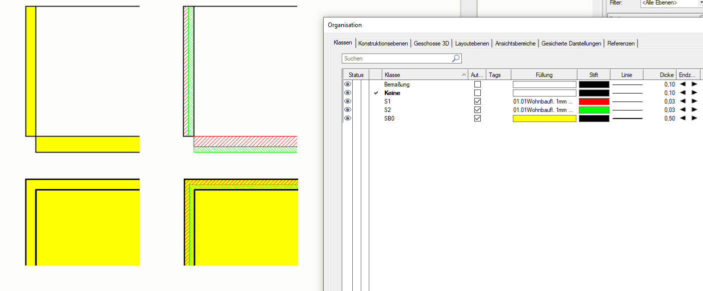
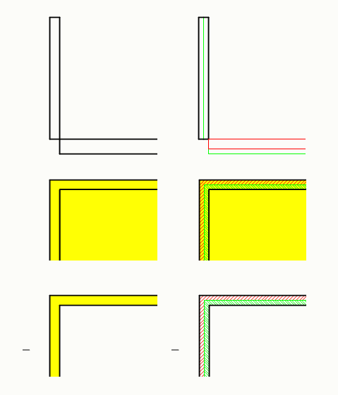
This would be "a solution" if the slabs had the line definition of each component split in upper and lower side, BUT they have not! Another inconsistency... There you have it... feel free and thanks in advance! SUPPORT_WÄNDE DECKEN.vwx -
Incoherence in detail level between walls and floors.
arquitextonica posted a question in Troubleshooting
Hello All, I discovered some incongruencies in the medium and high detail levels in walls. Now I see these incongruencies are yet deeper as they extend to big differences between the representation of walls and floors. In the attachment, the left side is with plan and section on low level (don´t know if its the right name in english, I use the german version) Walls and slab are constructed in a similar fashion. Container object in Class SB0 thick pen. Shells in S1 and S2. I could cope with the simple detail level, but the medium and high detail level are wron in plan and section. In plan I should in no way see the yellow filling behind the red and green AND in section I should either not see the section profile of the wall or see the section profile ALSO in the slab (which I´d very much prefer). Thing goes further as I just tried to represent the plans with horizontal sections and the representation is again different... this time at least I got rid of the yellow background in the detailed view and the yellow slab filling on the both surfaces which in my opinion is right...
-
Hello All. The "new" Materials are a HUGE improvement, BUT. It is really painful to start creating a new material to suddenly discover that when you are halfway, you don´t have the necessary texture created and have to "go out" of the menu and create it. Then you go back to the material and surprise! You also forgot to create the hatch... Could we have the creation easiness that we have when we forget the Classes and must create a new one, please?
-
Export 3D model as 2D DWG - no viewports, no symbols
arquitextonica replied to GK2's topic in General Discussion
This can in no way align with the BIM workflow. If I make two details out of a single section, these details 1. Should NOT be made into symbols. 2. IF they have to, they should originate from a single "mother" symbol of the BIM section. -
Export 3D model as 2D DWG - no viewports, no symbols
arquitextonica replied to GK2's topic in General Discussion
I just wrote a "complaint" about this topic. The output is not flat. If I make a layout with two details from a single section I become two symbols that are actually completely independent. This IMHO is a completely wrong use of symbols and merits the request from @GK2. Isn´t this a problem for Vectorworks Inc.? -
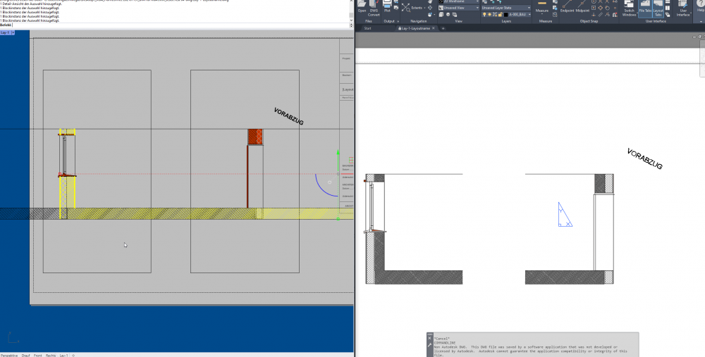
VW2022 DWG export improvements but not quite there yet...
arquitextonica posted a question in Troubleshooting
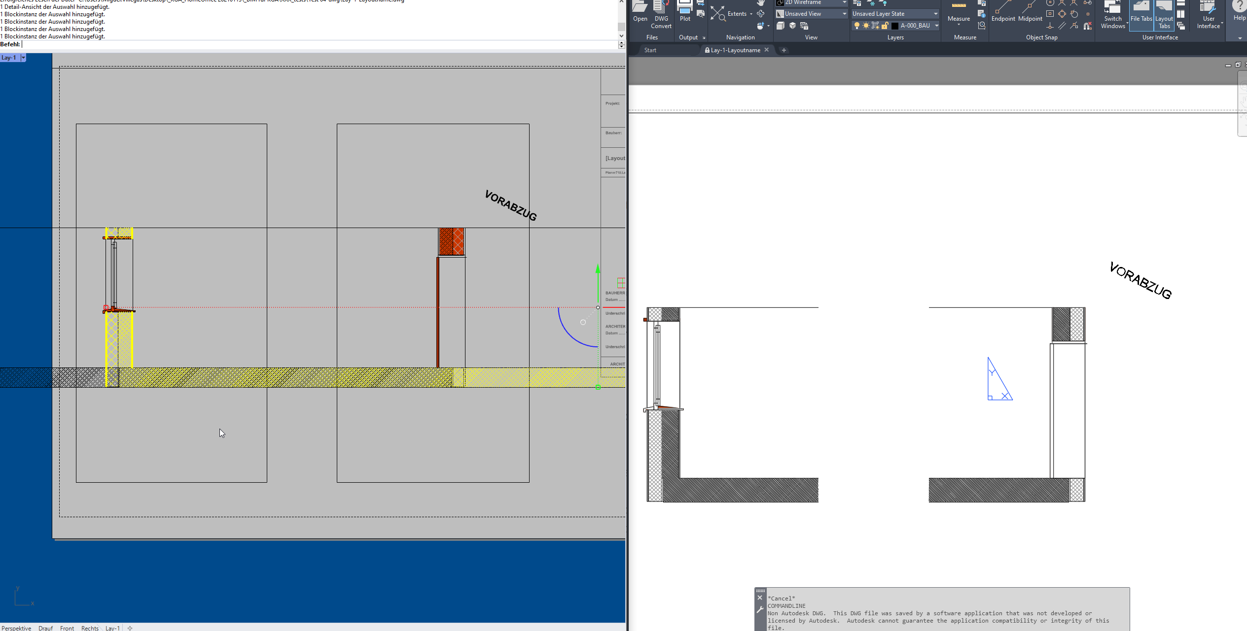
Hallo All! For some time now I´ve been fighting with the DWG Export issue. I´m glad to see the improvements in VW2022, but results are not satisfying yet. Size is much better in 22 (700Kb vs 19Mb in 2021) and rubble content is much lower (you can see the yellow area is the same on both cases, in 2021 the black collateral is HUGE. My point after this improvements keeps beeing the organization of the DWG itself. We can make several details of a single BIM section and layout them but the problem (for me at least) arises when in the exported DWG each of these details, that are exported as "framed views" contains not a drawing but a block, and that each of the block from the details (that all originate from the same section) are actually different to each other, thus completely thwarting the sense of the blocks! Is there an official stance on this topic? From what I read in the forum it is not regarded as a problem by VW-USA and therefore we can´t expect a solution... am I right? BIM is the present but there are a lot of planners involved in the design process that need DWG information exchange and I think this should be stable and trustworthy.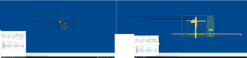
-
This is a very old post, but I´m really struggling here with the DWG export and can´t understand how it "still" works so awfully. As @Nina Ivanova said, the export "look allright" in Autocan´t viewers, but the reallity is they are NOT right. A single different block for each detail means that the whole Layer from which the detail was built will be copie for each detail. That situation made us have a single detail sheet with 10-12 details come up to over 60Mb in size just because the main section was big and allready detailed... Our only option so far is to explode the views into groups and then export, but that is absolutely contraty to any BIM process because we loose the automatic relation between model and plans. I know VW is powerfull in the "data visualization" but instead of multiplying the sections endlessly I´d rather loose some of this might and get a real solid outcome that is: - DWG Modelspace with the plans in 2D as we lay them in our Layers. - Layout with cropped view of the Model Space. Remember that DWG CAN control the visibility in a per view situation... Does this have to go into wishlist to get into consideration? BTW. the thing with the duplicate export in that a detailed view export outputs the class of the main container and also the classes of the components of top of it is another strong ISSUE...
-
Hi Mrs. Farrell. I was sondering if you could somehow rescue the Marionette? I´m trying to build an intelligent object in the form of a truncated pyramid and I´m really struggling with the solid modelling and the construction planes.