


JustinVH
-
Posts
597 -
Joined
-
Last visited
Content Type
Profiles
Forums
Events
Articles
Marionette
Store
Posts posted by JustinVH
-
-
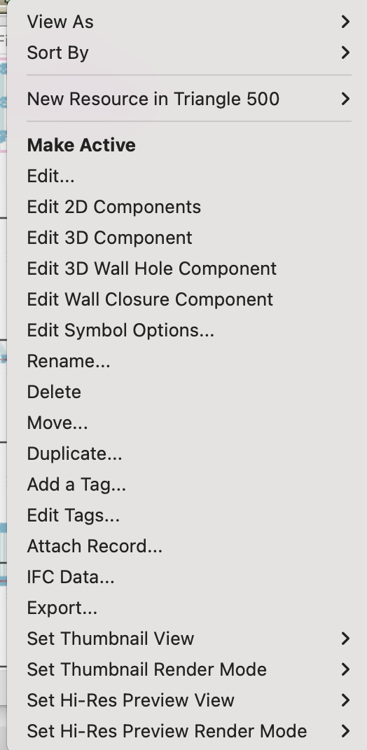
@Tom W.With VW2023 you are able to edit multiple symbol previews in both the large and small thumbnails, just use the Hi-Res options at the bottom of the right click menu.
-
 1
1
-
-
It looks like the bolt holes on the gusset plates are causing some soft of artifact to be drawn similar to how a multiple extrude can get artifacts between the upper and lower profile. Those bolt holes are just circles cut out of the poly line before the extrusion is performed so that is an oddity.
-
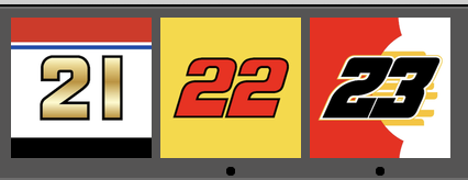
I like to use NASCAR number livery schemes.

-
1
-
-
- Popular Post
- Popular Post
I like to use NASCAR number schemes for my different versions.
-
4
-
 1
1
-
Do you know the particular model number of this hinge? We can add it to the list for development but that takes a long time due to the backlog of content development requests. Do you have the manufacturer CAD files of this hinge? If you are able to get those from the manufacturer that will help so that there is a starting point to create the symbol.
-
@HamishIf you ever upgrade to a newer version of Vectorworks you will have to update the the hoist record in your own symbols to the current hoist record in that version as there was a record change that occurred after VW2020. The change to the record was done due to some changes in the hoist functionality and what information is needed for the tool.
-
1
-
-
You need to add your file into the Hoist Tools folder that is located in either your user folder or in the application folder. As you are using VW2020 it is safe to put this in your application folder as there is no chance of the changes getting overwritten with a new RM catalog. This folder is located in Libraries>Defaults>Hoist Tools and the file name is Chain Hoist Symbols. Either add the symbols to the file that is already there or add your file with the custom symbols to that folder. You will have to restart VW for this to take effect and refresh your RM once the program launches.
-
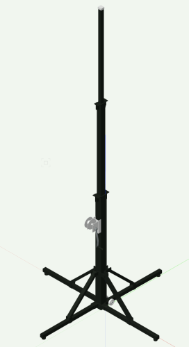
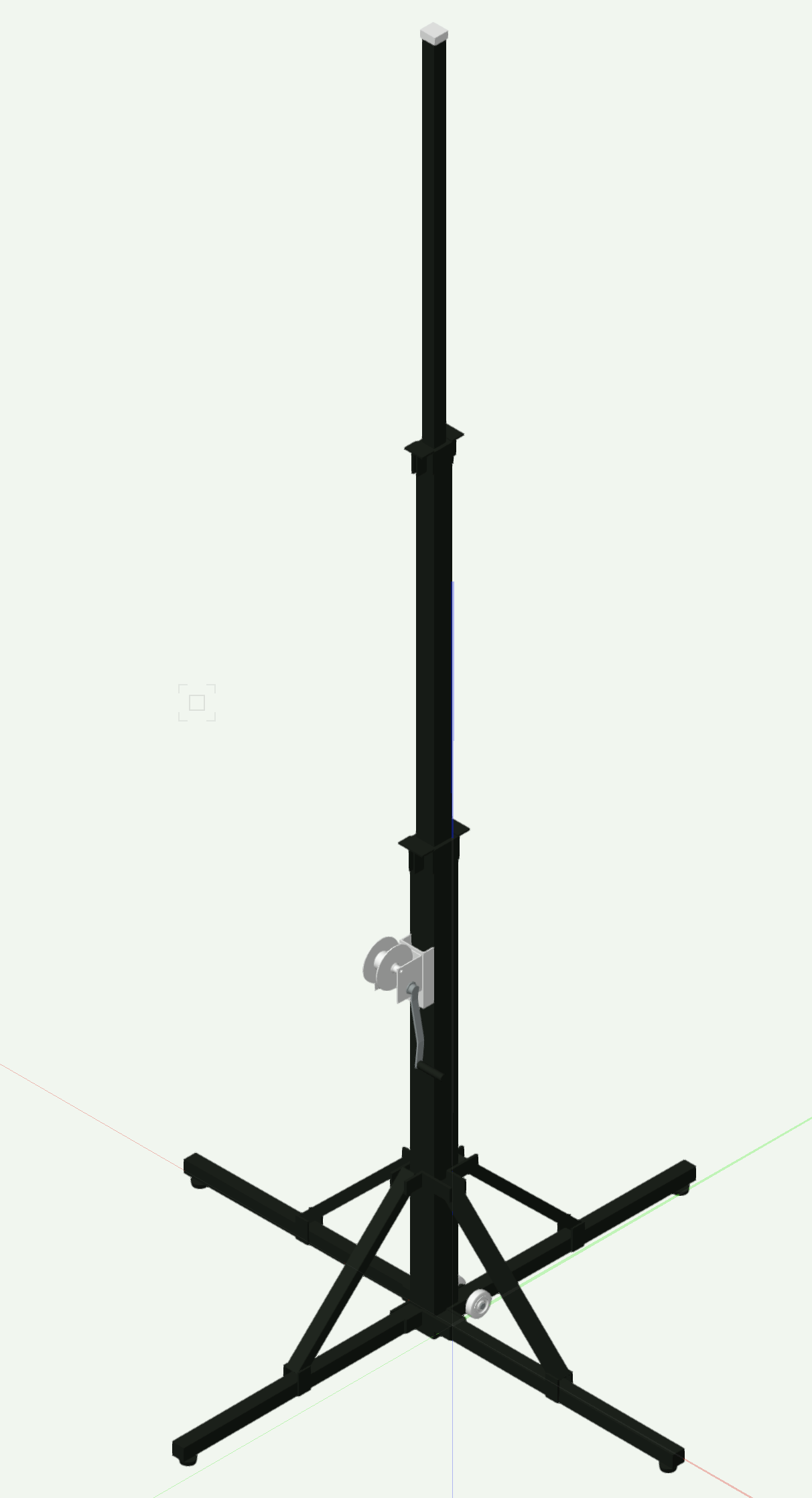
The Stage Lift tool in the Rigging toolset has a crank lift that is similar and as others have mentioned above there is a crank tower from Applied Technologies in the Premium content in the Objects - Ent Stage Folder, a screenshot of that symbol is in this message.
-
1
-
-
@jonniI took a look at your file and it looks like the straight pieces of FD34 1.75m have set their roll angle to 180° when inserted. The magnets, which are the green and white rectangle objects have a black triangle that points to the connection side of the truss and if the straight pieces get rotated this will cause the corner block to get rotated to match up the triangles. Also, any truss that does not have any 2D geometry in Top/Plan view has been rotated in some way and the 2D removed. I instantly noticed this when looking at your file in Top/Plan.
I would make sure to redraw the truss rig in Top/Plan making sure not to rotate any corners as it looks like you have the correct corners for what you want to draw. Also, note the red preview line/shape that is created before you click to insert trusses together. That preview will show you how those corners that build in the +/- Z Axis will be rotated at insertion. By staying in a top view it is easier to make sure that they don't roll which is what is causing the issues. Once the top rectangle with cross section is complete then you can switch to a 3D isometric and insert the vertical legs. Let me know if you have any issues.
-
 1
1
-
-
The truss corners were updated in SP4 of VW2022 so any shipped content should be corrected.
-
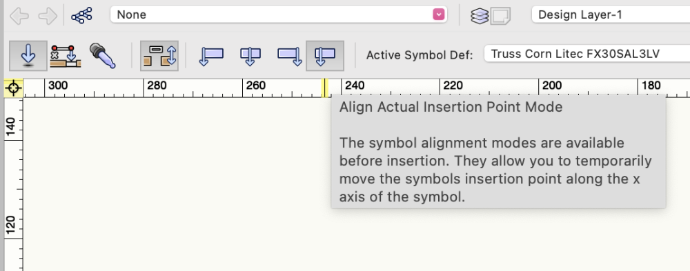
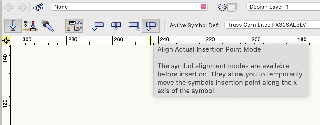
Have you tried switching to the 4th insertion option in the tool bar which used the actual insertion point?
-
1
-
-
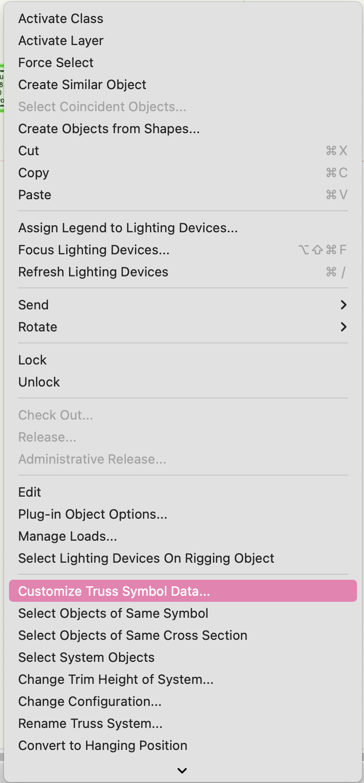
@39TechThe properties that Jesse is talking about are accessed by right clicking on the truss symbol on the design layer and clicking on the 'Customize Truss Symbol Data' menu.This cannot be done in the edit symbol modes, only from the design layer.
-
@39TechThe code issue that the error has been fixed but the content still has the errors as that can only be updated once a year. The corner will have to be manually fixed per the instructions that Jesse has listed above.
-
We have reached out to Unisson, Therio, and Arcofab on several occasions and even spoken to them at trade shows and have received no response to add their products into Vectorworks other than the currently limited selection from Therio. As we have mentioned to other users who are requesting other manufacturers it may take the users of their product(s) pressuring them directly to talk to Vectorworks in order to get the process moving as opposed to just us trying to connect with them. If a manufacturer sees that there is a need from their users to be in Vectorworks it might help to push them to respond to our emails or even reach out directly.
-
@Mickey You can have multiple connectable with types, all you have to do is place a semicolon followed by a space between each type.
-
1
-
-
@mhiltondesigns In the Miscellaneous Entourage>Entourage Vehicles folder there is a file of mobility scooters that contain more than just hospital style wheelchairs.
-
In the regular Vectorworks libraries there are 12" corner blocks for Tomcat. The blocks are located in the TC1212 Plated File and within that file is a folder of corners and hinges.
-
@Nina Agelvis Attached is a script that will remove the BrxTrussItemRecord from all of the truss objects in your drawing. You will first want to delete the Truss Record and the Rigging-Truss-Magnets class and all accompanying magnets from your drawing before running this script. Keep in mind that this is a brutal script that will strip all of the functionality or auto-connect and Braceworks. There is no undo after you run this script so make sure that you only use it on the truss objects that you want to make simple symbols. As the truss will be reduced to a simple 2D/3D symbol and not a parametric object there will be no ability to rotate in 3D and worksheet functionality may suffer.
Keep in mind that if you ever want this truss to return to functional truss you will have to reimport the symbol from the RM or do all of the truss record, auto-connect, Braceworks, and Truss Magnet setup manually.
-
1
-
-
This could also be done with a script to remove the BrxTrussItemRecord from all symbols in your document. This can be dangerous though because in order to restore the functionality the truss will have to be setup again as a truss object and not just a symbol. To second what halfcoupler asked; Why do you want to do this?
-
Those plus signs represent the middle of the truss profile and used to represent the old points for auto connect. Not sure why they are red and they should only be visible in wireframe.
-
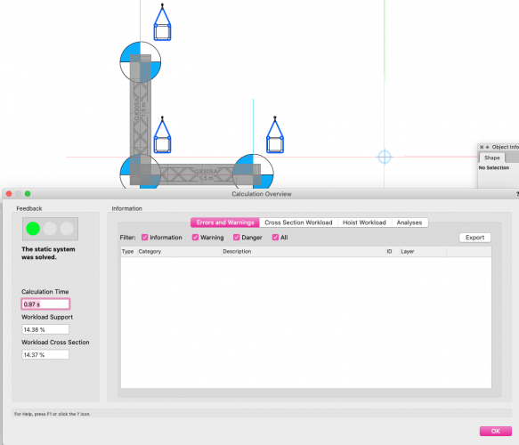
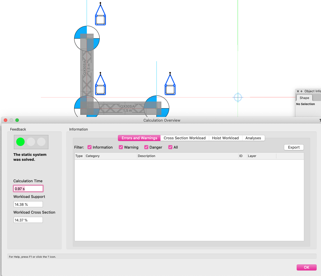
I was able to get the corner and the straight truss to connect without any issues. In order to clear the static system not supported issue I had to connect another straight piece of truss to the 90° corner of the corner block to make a "L" Shape. Once I added three motors to pick up all of the elements I achieved a successful report.
-
You can adjust the weight of the piece of truss yourself in the Truss Properties dialog to match what is given from the manufacturer. We are currently working with Eurotruss to do a complete review of all of the Vectorworks symbols and correct any issues with weights and other items. There is no timeframe for completion but luckily those are user editable values.
-
1
-
-
Thanks for pointing this out. That is an issue that I will be fixed. All truss should have a cross section assigned so that Braceworks will function properly. If the data is not available then it should be set to Rigid. Regardless, all truss should have values in length and width.
-
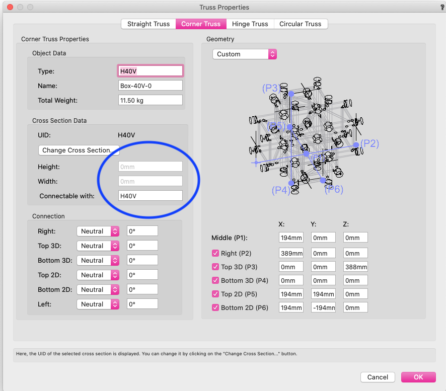
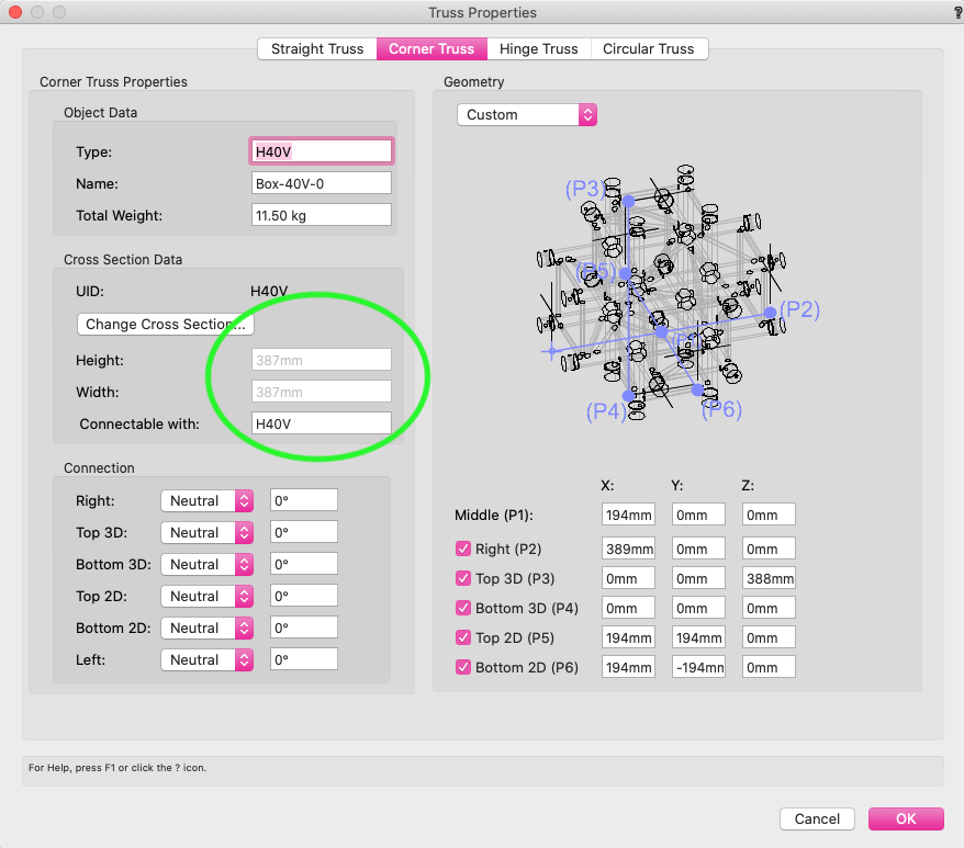
I took a look at the file and the issue is that the cross section values are showing the truss length and width dimensions of 0mm (screenshot with blue oval). If the dimensions have no values the auto connect will fail and that is why things were not connecting to the left. I was able to fix this by going into the Truss Properties and reassigning the H40V cross section to the piece of truss and clicking 'ok' in the dialog. The trick is to make sure that the length and width are 387mm (screenshot with green oval). By reassigning the cross section the length and with will auto populate because the dimensions are defined by the cross section. Once I corrected the missing dimensions the truss corner behaved like expected.
Resource Manager - adjustable size of resource thumbnails
in Wishlist - Feature and Content Requests
Posted
The large thumbnails is the other name for the preview pane that is the far right of the RM that shows the records, tags, and larger image preview.