


Nico Vindevogel
-
Posts
20 -
Joined
-
Last visited
Content Type
Profiles
Forums
Events
Articles
Marionette
Store
Everything posted by Nico Vindevogel
-
Version 1.0.0
118 downloads
This node is programmed in Dutch. The node is made to convert to a plug-in. Not converted, a Top-plan geometry will be visible. If you install the plug-in, the geometry will work as it should. Attached an English plug-in. ("AR_Cabinet2019 EN") For the non Dutch 🙂 See screen shots to understand "Front distribution", "cutout in sides", "shelves distribution" Enjoy. ver_2019 -
Thank you @DomC, This works very well. I use a few plug-ins made in marionette and converted via export script etc. Because I could not figure this out, I created a node that you have to connect behind the circle. It works with my node too (only in pio). I use a different function SetTopPlan2DComp (ver.2019). I still have to figure out how to stack the 2d tiles right so that the small ones are visible above the large surfaces. Thank you for spending your time and helping us !!! (Custom Node included) SetTopPlan2DComp.vwx Cube3DTocircleForum.vso
-
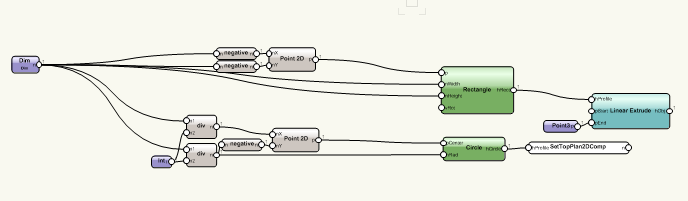
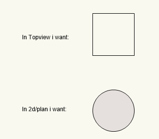
Does anyone have an example of how to include the 2d hybrid information in a marionette network? I have added a small network to clarify. The cube may only be visible in 3d mode. the circle in 2dtop plan view. In the vector script referece guide something is mentioned,(http://developer.vectorworks.net/index.php/VS:SetTopPlan2DComp) but are marionette nodes available? If someone has an example network, I would love to see it! Cube to 2dcircel.vwx
-
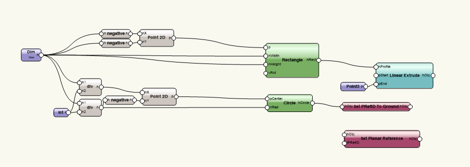
Hello Martijn, Maybe this can get you started. See file attached. Forum_Example_ToPio.vwx
-
python plugin object from marionette plugin object
Nico Vindevogel replied to RDS Casa's topic in Python Scripting
Hello, I think this will get you started. I did learn a lot from @Alan Woodwell https://www.youtube.com/watch?v=bBiai3iD-W0 -
Thank you for your quick response. It works perfectly! I test the same network with connected records. See attached. Now I have the problem if no rectangle is made, I get an error. But the network remains working well. Is there a way to not create 7 rectangles first and then delete what I do not need? I work on a cabinet which automatically calculates the width and height of the front. However, I want the ability to customize the layout like the test network. Removing the door from the original cabinet is not a problem because it is always calculated and, if necessary, removed at the end of the script. My goal is, if the test network input is empty, no panels will be calculated + the original door will be retained. The worksheet i am using to get te panel-data also attached. My non-working approach: Changing the handle from the set record node. from (0) to (None) #inObj = Marionette.PortIn( vs.Handle(0), 'obj' ) #To # inObj = Marionette.PortIn( vs.Handle(None), 'obj' ) Thx for any advice. Regards Nico NodeToStackPanels.vwx
-
Hi, I need a node that places the panels above each other. Attached a small network to explain what I want to achieve. Is there a possibility to solve this with a single node? I don't want to slow down the speed of my network. Example: I have a list like this: [0] =0 [1]=500 [2]=400 [3]=300 And i want the result of the list look like this: [0]=0 [1]=0 + 500 [2]=0+500+400 [3]=0+500+400+300 All hints are welcome. Regards Nico NodeToStackPanels.vwx
-
How to define a variable inside a node?
Nico Vindevogel replied to Nico Vindevogel's topic in Marionette
Hi DomC Yesterday i found a part of the solution: ->I want to store calculated values in the Fx_Value -It is typed in txt don't run it @Marionette.NodeDefinition class Params(metaclass = Marionette.OrderedClass): this = Marionette.Node( 'aNode' ) Fx_Value = (0.0) #__Old__Unused port in#Fx_Value = Marionette.OIPControl( 'Dim', Marionette.WidgetType.RealCoord, 0.0) Corpus_Breedte = Marionette.PortIn('0','Breedte') Dikte_Zijde_L = Marionette.PortIn('0','Dikte_Zijde_L') Dikte_Zijde_R = Marionette.PortIn('0','Dikte_Zijde_R') Waarde_Slag_Of_Groef = 2 def RunNode(self): Fx_Value = Corpus_Breedte - Dikte_Zijde_L - Dikte_Zijde_R + Waarde_Slag_Of_Groef self.Params.port1_out.value = Fx_Value + 20 +20 self.Params.port2_out.value = Fx_Value + Fx_Value2 The solution for boolean value i didn't find: Maybe i have to try something like below... @Marionette.NodeDefinition class Params(metaclass = Marionette.OrderedClass): this = Marionette.Node( 'aNode' ) Marionette.variable_name = False ###Not working #### variable_name = False def RunNode(self): Fx_Value = Marionette.variable_name vs.Message(str(Fx_Value)) -
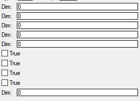
Hi, I want to store a value inside a parameter. I don't want to create a portIn to define a parameter, or use the OIPControl method. Is there an other way to store an calculated value inside my node? I think this must be easy, but i can not find the appropriate syntax. This is what i don't want to use: Fx_Value = Marionette.OIPControl( 'Dim', Marionette.WidgetType.RealCoord, 0.0) OR Fx_Value = Marionette.PortIn('0','Calculated value') Can i for example do something like this to store a value. Fx_Value = (),Realcoord,0.0 Below you can find my code to check 2 input ports. At the moment i store the result in a parameter defined by a Marionette.PortIn. My network is running but the node looks ugly. Lots of unused input ports, Or OIPControls whithout a destination. Example: #___Begin___Controle Boolean self.Params.Fx_Value.value = self.Params.Slag_Of_Groef.value > 0 if self.Params.Fx_Value.value: self.Params.breedte_Rug.value = Waarde_Slag_Of_Groef + Corpus_Breedte - Dikte_Zijde_L - Dikte_Zijde_R + Waarde_Slag_Of_Groef else: self.Params.breedte_Rug.value = Corpus_Breedte - Dikte_Zijde_L - Dikte_Zijde_R #___Einde___Controle Can someone point me in the right direction? Pic off unused oipcontrols:
-
Marionette - Duplicate and Copy Paste Error
Nico Vindevogel replied to Nuno Antunes's topic in Marionette
Hello @ Nuno Antunes , Didn't try your network but i had same problem before. Just delete the 1_ and 2_ before the name off the node, and all will be fine. -
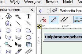
I had same problem. I Found that if the zero point off the workingplane is schifted, my network didnt work. Try to reset to user zero point. It is the target in te left upper corner. A yellow color is bad.
-
Hello, @Stephan Moenninghoff Figured it out. See node attached. I use it in a ordered list to place it on the right spot. Seperator.vwx
-
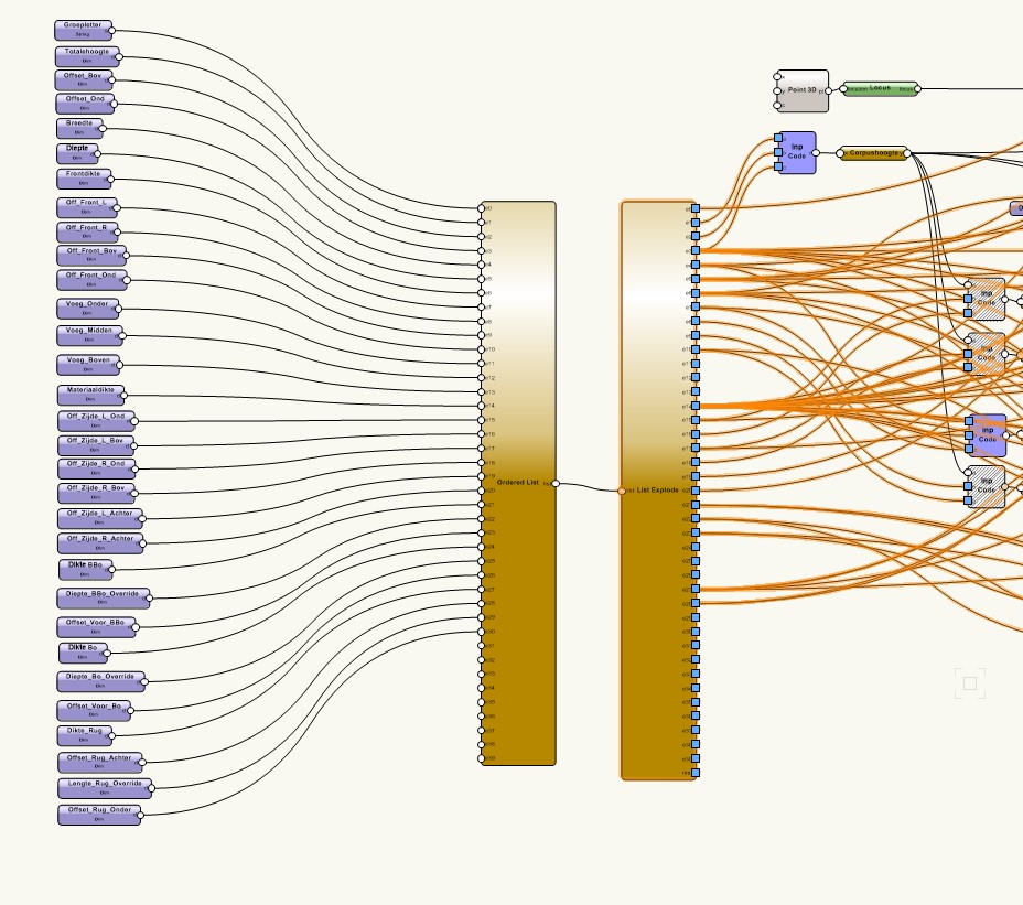
Prefixing the imput nodes to sort oip does not work as it belongs for me. If you create a simple box with a width of 600. Then you insert the box into the drawing and change the width to 400. You copy paste a new insance of the box and you get a box of 600 wide again. While you want a box of 400. (600 is used when the network is wrapped) To sort the oip I use following method. First I place all my input fields in an ordered list, then i use immediately a list explode node. To wrap the network you have to right click on the list explode node and NOT on just a node you preffer. @Stephan Moenninghoff Can you post an example how to use te seperator? I see in the pic above you figured it out... Thx
-
resolved. 1st I used a prefix to sort the input in oip. That is not working properly. 2nd the zero point should be X 0 Y0 (in the new drawing). As the little square at the top left is yellow then the script does not work. 3rd import the scripted symbol first to the resource brouwser, then drop it into drawingspace. Thx for the advice. Greetings, Nico
-
Multiple records in 1 marionette script
Nico Vindevogel replied to Nico Vindevogel's topic in Marionette
@Alan Woodwell I spent hours searching for a solution, and apparently you had it already in minutes. Keep up the good work. And many Thanks. -
Multiple records in 1 marionette script
Nico Vindevogel replied to Nico Vindevogel's topic in Marionette
@MFarrell Thank you! Thank you! Thank you! This solves my quest. -
Multiple records in 1 marionette script
Nico Vindevogel replied to Nico Vindevogel's topic in Marionette
Hi Marissa, You are spot on, I want different data for each extruded rectangle. If it's possible to do that it would be great. @ Alan, thank you for trying my network. the worksheet was my first idea, unfortunately i can not filter the data to another worksheet. A better way for me is to work with records. -
Hey, I added a small part of a script to explain where I get stuck. What I want to achieve is to link a record to each component made in the script. I want to use records because i want to filter the data. Unfortunately, I think only one record can be linked to an object-node. In my example I create 2 records (same name) and only one is visible. Is there a way to associate a record to each piece in the script? It is not necessary to see the records in the oip , if its possible to get the data in a regular worksheet it would be perfect. A worksheet in the script is possible (used custom nodes #Created by MFarrell) . In the worksheet I can see the data from the two parts created. Problem there is, if the object instance returns 5 times i get only one worksheet in the resource manager. Can someone help me out? Maybe i have to approach it differently. Every hint is welcome. 1objectnode2records.vwx
-
Thanks for trying my network. Perhaps adding a pio handle is the solution? If i use the move-copy tool, the symbol returns the default values when it was created or wrapped to the object node. I just can not figure it out where i have to add the pio handle. Some one has an example available? Nico
-
Hello forum members. I created a simple 2d cabinet marionette network. It works fine as long i use it in my original file. If i create a symbol from my "object node" and use it in the original file it works. If i open a new file and place the symbol using the resources - favorites pallet, it sometimes works... If my network would never work , maybe i was capable to find the solution. For the enthusiast that what to help me, add my file to your favorites and try to change the "corpusbreedte" ("Cabinet Width") and see what happens. Maybe it works... My errors are not always the same it differs from a error in oipcontrol to a mixt up object from the original. Nico ps. Sorry for my lack of language; All two of them "Marionette" and English. OS: window10 ; vw2016 architect ; interiorcad ; CabinetFront.vwx


