


BG
-
Posts
382 -
Joined
-
Last visited
Content Type
Profiles
Forums
Events
Articles
Marionette
Store
Posts posted by BG
-
-
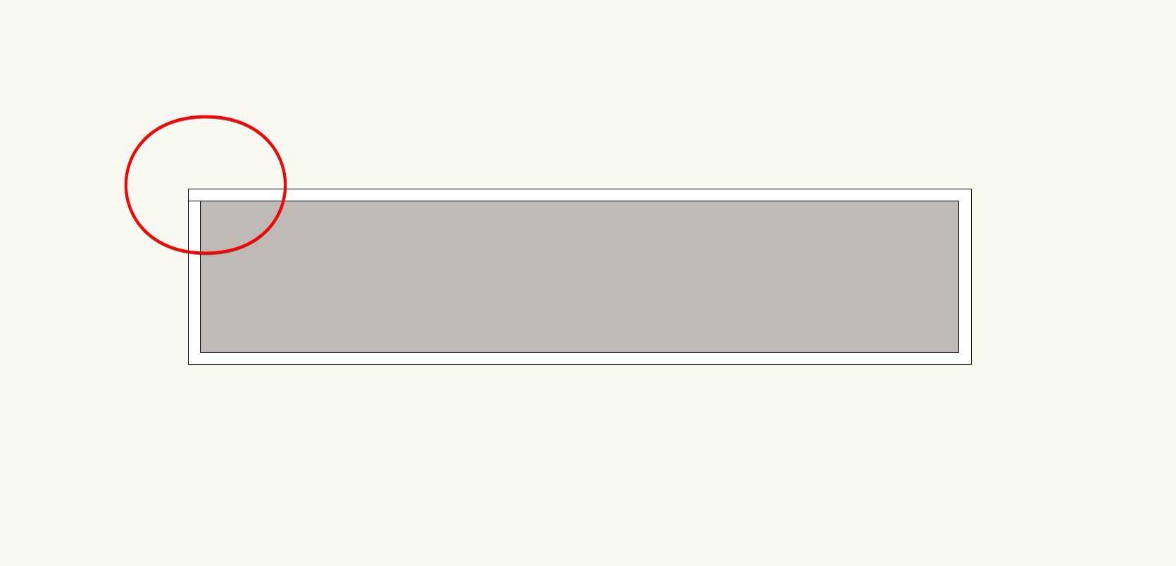
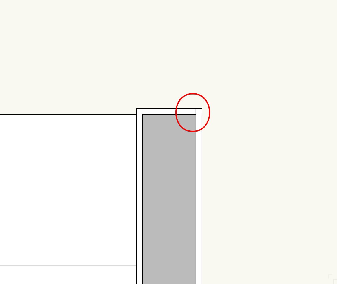
I have a issue with modifying some objects where the change does not show until the screen is refreshed by zooming in/out etc. This is with the latest SP in VW2018. Is this a known issue, and resolved in 2019? In the attached example, a rectangle is resized using the OIP. You can see the ghost image of the modified shape but the original shape remains on screen until refreshed. It's more of an annoyance, but it would be preferable if this behaviour wasn't there.
-
It would also be really good, when any viewport is linked to another viewport/sheet, when creating a PDF set of drawings, it automatically creates a link, so you can just click on the drawing title label it and it takes you to that viewport/sheet.
-
 2
2
-
-
It would be good if individual keynotes could have their formatting changed. i.e font, size, bold, italic, underline etc
-
3
-
-
@JMR We tried using the space tool but as you mentioned, it is far too slow to use productively, and creates all sorts of lag with the drawing file, even on a blank file. It use needs to be instantaneous with no noticeable lag or delay. Hopefully this has been fixed in 2019, but it doesn't sound like it has.
-
It would also be good if wall components heights (i.e. shape) could be adjusted individually too.
-
Hi. We've actually found that it doesn't affect our work. In reality the top plates of walls are usually flat anyway so it kind of mirrors how walls are built. But you're right, there is no way to get the tops of walls angled to match whatever you are fitting them to unless the wall runs parallel with the object slope.
-
Good example from Carmelhill, we would far prefer that some of these existing tools get updated so that they are usable rather than adding any new features. A properly functional HVAC tool would be very useful.
-
4
-
-
One thing to note, when walls are 'fitted' to objects, their top surface always remains horizontal, i.e. if a wall is running perpendicular to a slope, the top of the wall won't be sloped to match the object. The slope of the wall will follow the object slope but the top surface of the wall will remain horizontal. So you usually end up with slightly odd corner junctions which is what it looks like you are experiencing.
-
Let's hope this is fixed in the next service pack. This drives me crazy having to constantly change the settings back to screen plane, plus all of the objects that have inadvertently ended up on the layer plane by mistake.
-
It's very disappointing. We are not going to even consider using 2019 until SP3. Even 2018 still has display glitches and hidden line render anomalies etc. With each release we hope for a more complete and stable version - a genuine 'upgrade' that can be used productively from day 1. Fingers crossed for v2020.
-
2
-
-
As Line-weight has mentioned, we always end up drawing these things twice, or the other method we use it to extract the surfaces of the object to get rid of the unwanted join lines in elevations. Only problem is, if the object changes shape or location etc, you have to remember to update all of the items used to create the object including any extracted surfaces.
-
We have had this issue a few times. Deleting the Heliodon and inserting a new one fixed it.
-
Is this fixed in VW2018 SP5? 3D Loci not showing up where they should in SP4.
We are not upgrading to 2019 until at least SP3 or SP4 due to all of the bugs identified in this forum. We understood 2019 was to be a quality focused release, but it appears to be anything but unfortunately.
-
Thanks Jim, seeing what you have highlighted showed me what I was doing wrong. I was selecting one wall lining and then clicking at the end of the wall rather than the lining on the other side. Simple. Can't believe I didn't try that, been bugging me for a long time...haha
-
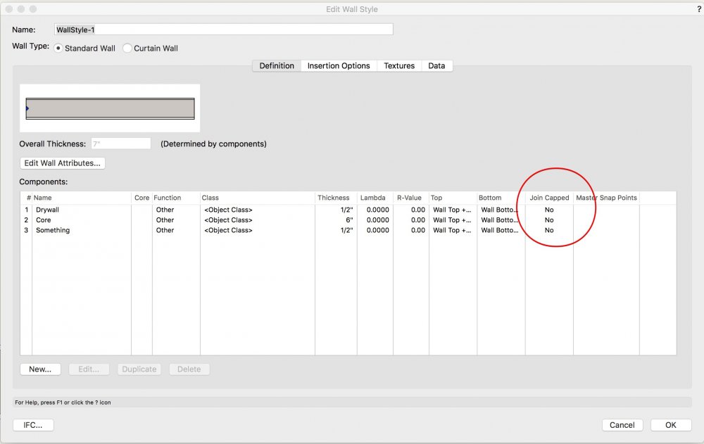
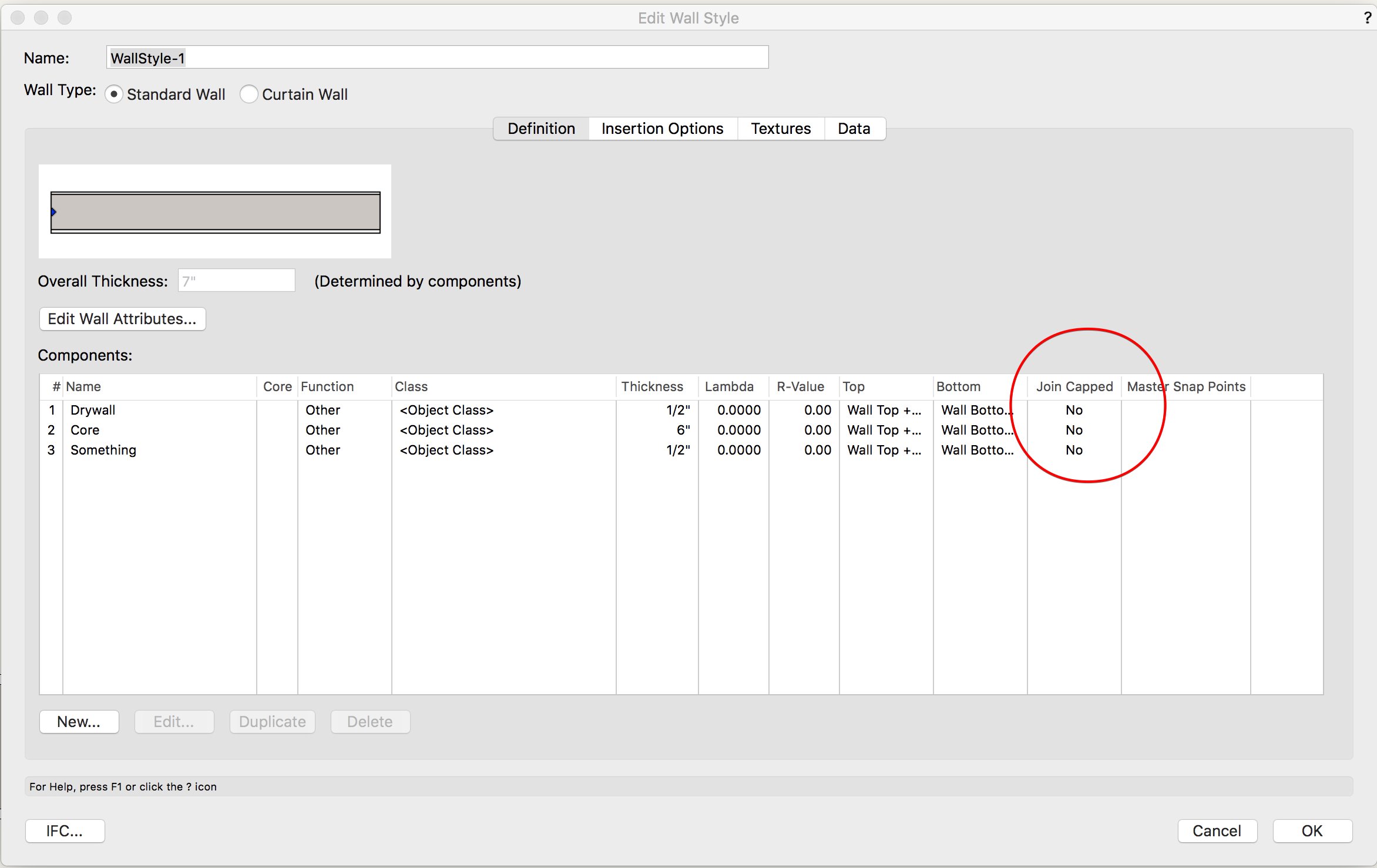
Hi Wes. I'm still having no luck. The wall style in the file you sent had the 'join capped' set to off. Even if I turn that on, I still can't get the cap to show without a line.
What I am doing is - After selecting the wall cap tool, I am clicking once on the lining component, then on the end of the wall. The cap appears fine, but with that errant line?
I tried adding a cap on the other end of the wall you sent me with the same result.
-
Perfect. Could you please re-attach in VW2018 format?
Thank you. Which mode did you use & was it a one-step process?
-
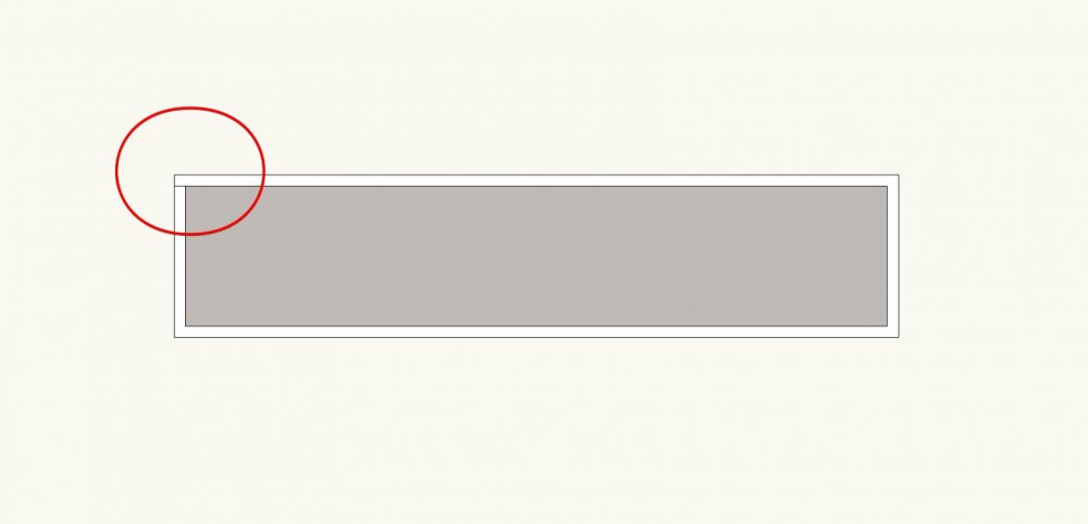
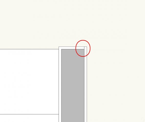
Hi. Can anyone tell me how to add a wall end cap without a rogue line appearing? See image attached. The rogue line appears in a hidden line render in 3D which is unwanted. It may be user error but I have tried using the various modes of the tool.
Thanks.
-
What is need is a proper grid line that shows up on plan and section/elevation with a standard grid line marker. We have been using 3D polygons for showing grid lines in section for some time, but only using them a guidelines, and then annotating over with the correct line type & turning the guide grid lines off.
-
1
-
-
These lines could also be the corners of walls adjoining the exterior wall. Check that you don't have any instances like that, otherwise the lines will always show.
-
Hi
We don't open the database directly, but edit it using the Notes Manager within the callout tool. From what I understand, the database is formatted very specifically and you would have to be very careful not to mess up the specific formatting to ensure it still works correctly.
-
We have done a lot of roofs like this, and it is just a matter of working out the roof plane direction and pitch. You can create a 3D object of the roof plane first to work out both of those.
-
1
-
-
Thanks Matt, that works a treat for covering unwanted linework etc. How hard would it be to enable lines to be trimmed or extended to the break line?
-
2 hours ago, fabrica said:
think a 'to do' list is required 😀....... wishing doesn't do it anymore!!
Agree, each year goes by and the same 'basic' wishes are repeated by the users. And these are fairly fundamental tools for an architectural practice - A Window Schedule!
-
2
-
-
13 hours ago, rDesign said:
Here’s a few old wishlist items / threads requesting this, dating all the way back to 2004:
https://forum.vectorworks.net/index.php?/topic/40507-break-line-trim/
https://forum.vectorworks.net/index.php?/topic/32415-trim-to-break-line/
https://forum.vectorworks.net/index.php?/topic/11722-break-line-and-trim/
2004, Wow, that's ridiculous. Some of these seemingly 'minor' improvements would make a big difference to the everyday use of the software. I still would prefer the upgrading of functionality of all of the existing tools rather than adding new 'flashy' tools with each new VW release.
-
2
-
Object Update
in Troubleshooting
Posted
Following on...when placing a symbol, the symbol does not show up until the screen is refreshed.