


michaelk
-
Posts
6,389 -
Joined
-
Last visited
Content Type
Profiles
Forums
Events
Articles
Marionette
Store
Posts posted by michaelk
-
-
The kobj… lines are constant definitions. Later on in the code the coder will want to use the integer value for OnWigetPrep and rather than look it up or remember a hundred of these numbers they are defined at the beginning of the code in the CONSTANT section.
The functions that require those values are used when the plug-in object is "event aware". Event aware plug-ins can do things like have Styles that are recalled from a stored symbol in the resource manager.
They don't show up in the reference because they aren't functions. They are a common practice. Not part of the language. It's entirely possible that we are all copying that from @Julian Carr and @JBenghiat.
Don't worry about that for a while.
You will have a few years of joyfully improving your productivity by making useful tools and menu commands before it seems like a good idea to subject yourself to that torment. Maybe by then ChatGPT will be able to write plug-ins for us :-).
-
 1
1
-
-
My experiments with ChatGPT and Vectorscript always return VERY verbose code at the very best. Often ChatGPT hallucinates functions. And it can't handle plug-in objects very well - if at all.
The good news is you need MUCH less code than you think. That's the beauty of writing plug-in objects.
It can't handle the plug-in definition at all. And I'm not sure from your example that you are defining the plug in.
If you want to make a plug-in object that draws a square of parametric values using a point plug in:
In Vectorworks, go to Tools>Plug-ins,>Plug-in Manager…
Chose New.
Give it a name and select Point Object.
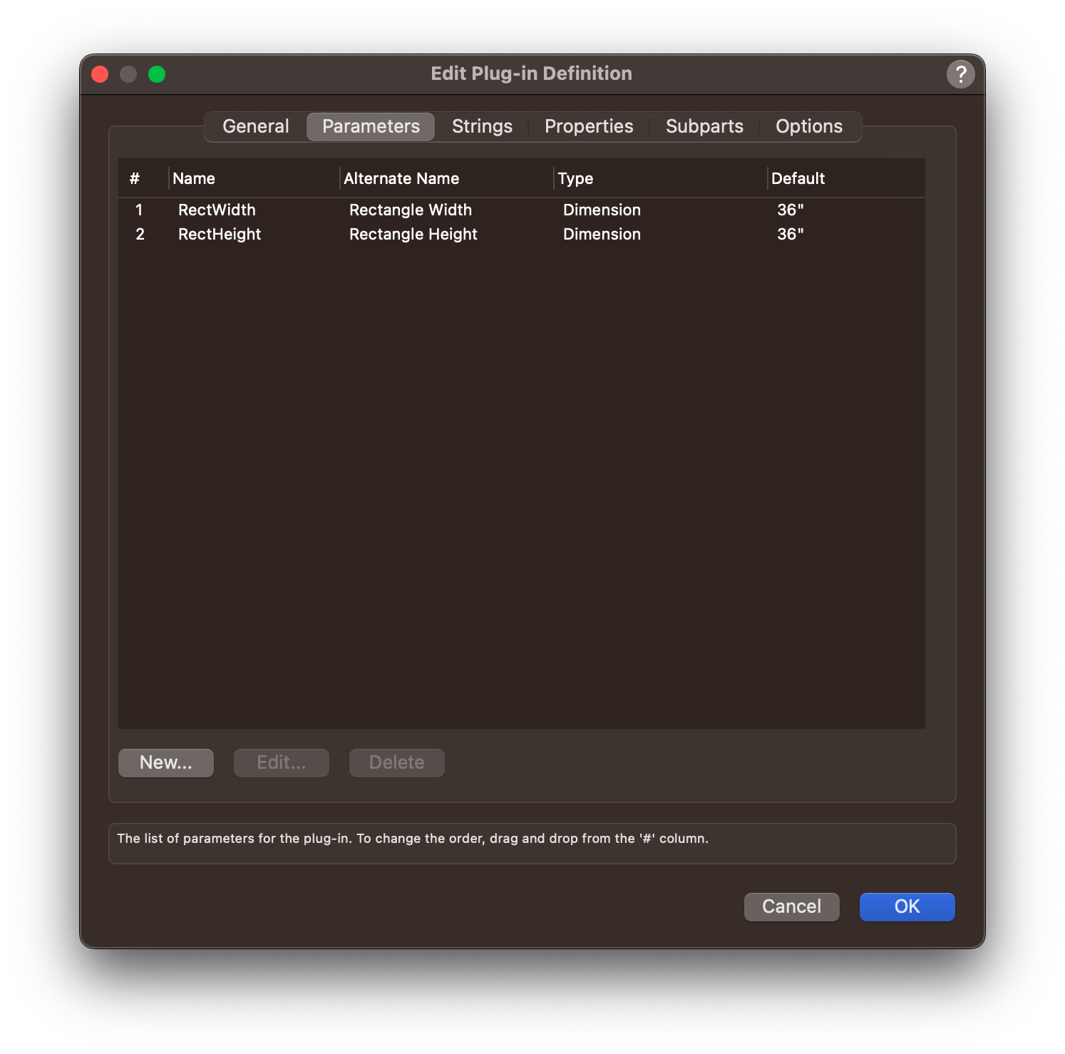
In the parameters tab do this:
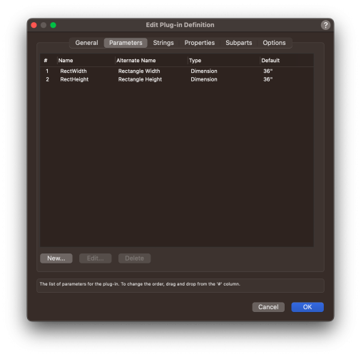
The name in the Name column is what you use in the script (with a p prefix). The Alternate Name is what appears in the OIP and in a worksheet.
Believe it or not, this is the entire script you will need:
PROCEDURE ParametricRectangle;

BEGIN
	RectangleN(	0,0,
			1,0,
			pRectWidth,pRectHeight);
END;

RUN(ParametricRectangle);
pRectWidth and pRectHeight will be the values in the OIP for Rectangle Width and Rectangle Height! Changing the values in the OIP (or in a worksheet) will change the size of the rectangle.
RectangleN is a standard way of drawing a rectangle. The first two numbers are the starting point. With plug in objects the insertion point of the object is 0,0. The next two numbers define the direction of the base of the width of the rectangle. 1,0 means it goes to the right and not up or down. -1,0 goes to the left. 1,1 goes at a 45º angle up and to the right. The actual values don't matter. Just if they are negative, zero, or positive. The last numbers are the opposite corner of the rectangle.
You don't have to write them as 3 lines. I just find that easier to read.
If you want to make a plug-in object that draws a square with handles at the corners:
In Vectorworks, go to Tools>Plug-ins,>Plug-in Manager…
Chose New.
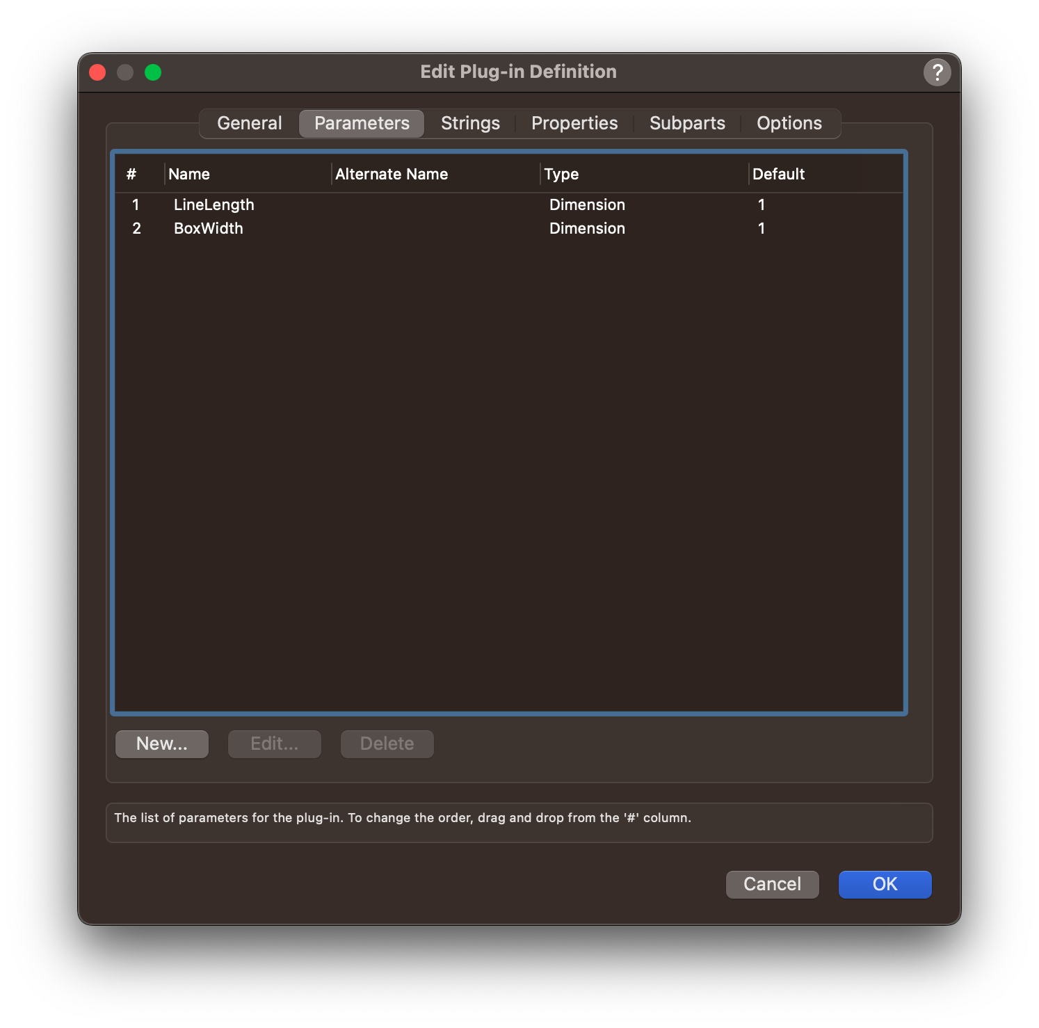
Give it a name and select Rectangle Object.
For a Rectangle Plug-in Object it will automatically add the width and height parameters!
So, without even lifting a finger the parameters will look like this:
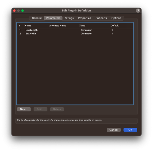
The script will be something like this (I added diagonal lines just to give it something to do :-):
PROCEDURE RectRect;

BEGIN

	RectangleN(
		0,(0-(pBoxWidth/2)),
		1,0,
		pLineLength,pBoxWidth);

	MoveTo(0,-pBoxWidth/2);
	LineTo(pLineLength,pBoxWidth/2);

	MoveTo(0,pBoxWidth/2);
	LineTo(pLineLength,-pBoxWidth/2);

END;

RUN(RectRect);
With this plug-in you can either drag the handles of the rectangle or type in values in the OIP.
Note that this plug-in will have two insertion modes. The second one is the one that makes sense. But I don't know any way to make that the default :-).
In the second insertion mode the linelength is the first line you draw and the boxwidth is what a human would think of as the height.
For reasons someone may soon tell us, but unknown to me for many years, the boxwidth (height) is measured from the middle of the rectangle. So you have to do the division by 2 business.
I'll attach these two plug-in objects so you can take them apart and see how they work. Let me know if you need help installing them.
Post back with any questions.
Welcome to a lifetime of madness.
EDIT: Should have mention in directions above. After you create the plug-in object you still need to add it to a workspace so it will show up in a tool palette or menu.
-
 3
3
-
1
-
-
I wonder if the OS matters.
Is this an issue on windows 11 and not on Macs?
-
That's not what I'm seeing in 2024. When the Move By Points tool is active and the first mode is either Move and Duplicate Mode or Distribute Mode, then hitting the P key will highlight the current entry in the Number of Duplicates field so that typing any number will replace the current entry.
-
1
-
-
Yes. The criteria is LOCATION. When you use Location the choices are "is within" and "is not within" and then you will see a list of possibilities.
By default the space objects will have a UUID # that is I think 16 hexadecimals inside curly brackets. If you click on a space object that same UUID will be in the Name field at the very very bottom of the OIP. You can change that to something more human readable and that new name will appear in the criteria list.
If you want to go the other way and your space objects have names in the Space Name field, then you can use the call =GetSpaceNameforObj in the database header row and it will return the room name for all the spaces that object is contained within, separated by a comma.
-
3
-
-
Just post the .vwx files here and someone will convert them for you.
-
-
@Alex11 Not that I know of. If you send it in a PM to me or another moderator we can do it for you.
-
16 minutes ago, Pat Stanford said:
I believe that the original MiniCAD code was all written in Pascal and only much later converted to C.
It was. I met Richard Diehl once and he told me about writing the original MiniCad in a version of Pascal (Turbo Pascal??) that would compile on his (I think…) Mac 512.
-
1
-
-
Just learned that Niklaus Wirth passed away on January 1, 2024.
https://en.wikipedia.org/wiki/Niklaus_Wirth
You could argue that Vectorworks wouldn't be what it is without him.
-
- VW>Preferences>User Folders>Reveal in Finder
- Find the Plug-ins folder. Put the .vsm file in that folder. (I find it very useful to make the user folder a favorites in Finder)
- Restart VW.
- Tools>Workspace>Edit Current Workspace (or choose Workspaces… and create a new workspace based on a copy of the current one)
- in the Workspace Editor > Menus Tab
- On the left will be groups of menu commands. Jesse's are usually in a group called JNC. Find the menu command you want
- On the right are a list of all the menu commands in that workspace in VW. Open up the target menu group and
- Drag the new menu command on the left to the desired location on the right.
- Hit OK.
As a bonus, you could just grab the JNC heading on the left and drag it to the right. You will now have a JNC menu. I'm currently using 9 JNC menu commands!
-
1
-
Are they attaching a script to the saved view?
-
1
-
-
You may have found a bug.
Here's one workaround:
- Pull the windows out of the wall.
- In Settings>General set the Insertion Relative to: Center of Jamb.
- Reinsert the window.
- Offset as necessary.
-
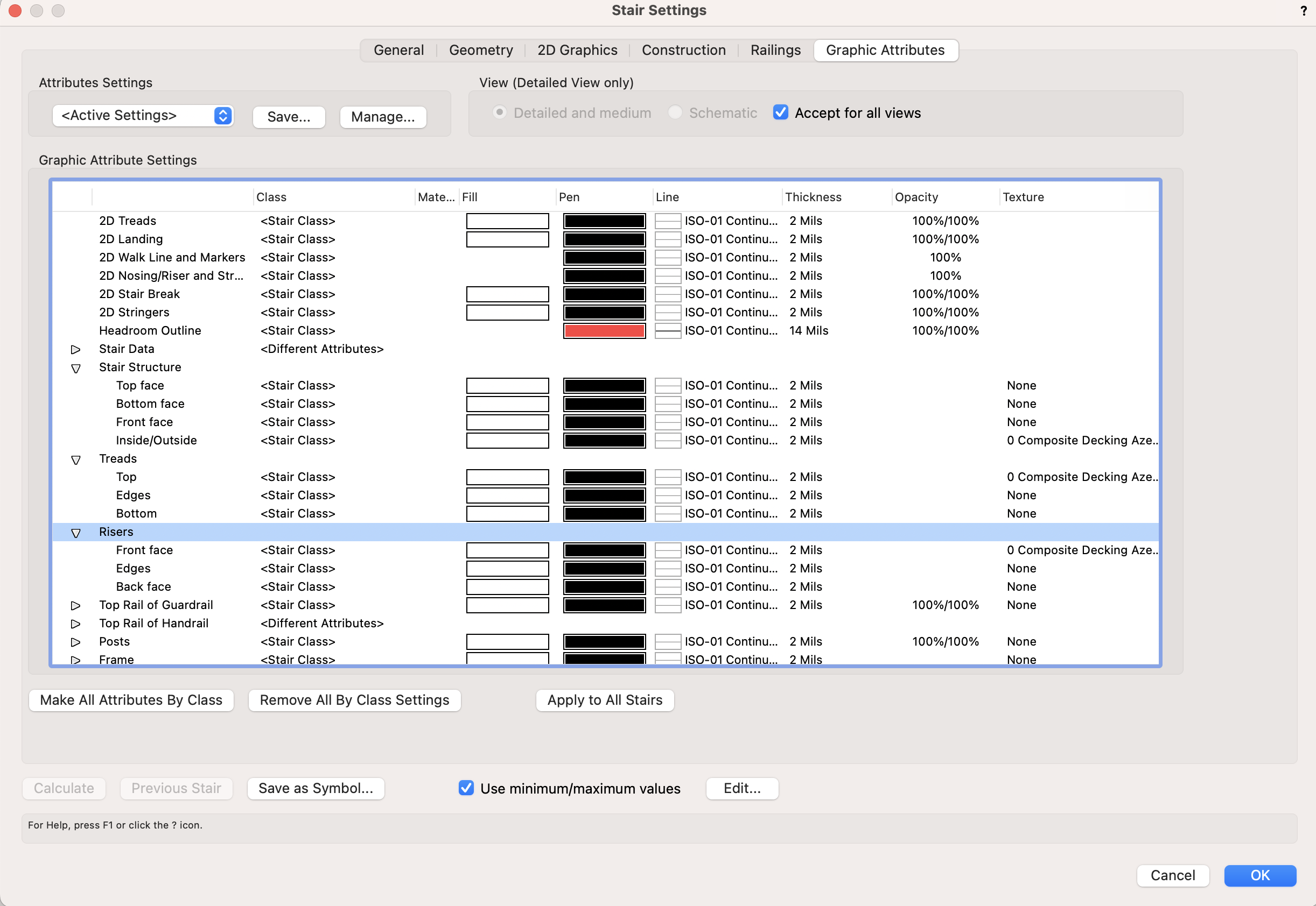
First remove the texture from the stair object in the render tab of the OIP.
Then go to the graphic attributes of the stairs and set the texture of every part you need of the stair.

I usually make a version of the texture where the hatch is turned 90 degrees just in case.
-
Can you copy the wall with that window into a blank file and post it?
-
Is that a custom window or two windows directly adjacent to each other?
-
Still there!
(Not optimized for dark mode)
-
1
-
 1
1
-
-
-
-
You CAN encrypt plug-ins in 2024 one at a time using the method in my post above.
I don't go for all the fancy stuff Josh, Jesse, and Sam do. 🙂
-
2 hours ago, Marc Davies said:
Francisco. Sorry no immediate answer for you. However, my experimenting with chatGPT means you can get it to write most of a Vectorworks script for you to do what you want.
Be very careful w/ chatGPT writing VS. I have tried it and found that chatGPT often hallucinates functions that don't exist. If you want it to do something super simple - like draw a rectangle of a given size - it can do it, but often in a bizarre, verbose way.
I'm sure it will get better in a year or two and we will all be writing fabulous scripts 🙂.
-
1
-
-
-
File > Document Settings > Document Preferences… > Display Tab. Second checkbox from the top.
-
2
-
-
You might find this helpful.
I made a couple scripts when 3D Web views first came out to open all the doors in a drawing so the client wouldn't have to crash through closed doors. One opens all the doors that have "On Schedule" checked. The other one returns them to their original state. It uses User Field 9 and 10 to store the original state of the door.
I'll attach a file with the scripts and a couple doors to swing open and closed.
Here is the script to open the doors in 3D:
PROCEDURE OpenTheDoor;

{14 April 2017}
{Badly scripted by Michael Klaers}

{This script preps the doors in a drawing to be ready to 'Export Web View'
It preserves the 3D Open boolean and the open angle of each door in User Field 9 and 10
and then sets the 3DOpen to TRUE and the Open Angle to 90°}

{There is a companion script that restores the doors to their original state}

VAR

	ShouldILeaveThisOpen	: STRING;
	OriginalOpenAngle  		: STRING;

{------------------------------------------------------------Record & Open Procedure}

PROCEDURE RecordAndOpen(h : HANDLE);
	BEGIN


		ShouldILeaveThisOpen := GetRField(h,'Door','3DOpen');
		OriginalOpenAngle := GetRField(h,'Door','OpenAngle');
		SetRField(h,'Door','UserFld9',OriginalOpenAngle);
		SetRField(h,'Door','UserFld10',ShouldILeaveThisOpen);
		SetRField(h,'Door','OpenAngle','90');
		SetRField(h,'Door','3DOpen','TRUE');
		ResetObject(h);

	END;

{-----------------------------------------------------------------------Main Program}

BEGIN

ForEachObject(RecordAndOpen,(((R IN ['Door']) & ('Door'.'OnSched'=TRUE))));

END;


RUN(OpenTheDoor);
Change the number in SetRField(h,'Door','OpenAngle','______'); to be whatever angle you want.
This is the script to restore the doors to closed:
PROCEDURE CloseTheDangDoor;

{14 April 2017}
{Badly scripted by Michael Klaers}

{This script restores the doors in a drawing after 'Export Web View'
It recalls the 3D Open boolean and the open angle of each door from User Field 9 and 10
and then restores the 3DOpen Boolean and the Open Angle to their original values}

{There is a companion script that records original state of the doors.  Run that one first.}

VAR
	OriginalOpenAngle  		: STRING;
	ShouldILeaveThisOpen	: STRING;


{------------------------------------------------------------Read & Restore Procedure}

PROCEDURE WereYouBornInABarn(h : HANDLE);

	BEGIN

		OriginalOpenAngle := GetRField(h,'Door','UserFld9');
		ShouldILeaveThisOpen := GetRField(h,'Door','UserFld10');
		SetRField(h,'Door','OpenAngle',OriginalOpenAngle);
		SetRField(h,'Door','3DOpen',ShouldILeaveThisOpen);
		ResetObject(h);

	END;

{----------------------------------------------------------------------Main Program}

BEGIN

ForEachObject(WereYouBornInABarn,(((R IN ['Door']) & ('Door'.'OnSched'=TRUE))));

END;


RUN(CloseTheDangDoor);
Much faster than doing it manually 🙂
-
3
-
Fast way to change worksheet columns sort order?
in General Discussion
Posted
Glad you like them!