


michaelk
-
Posts
6,389 -
Joined
-
Last visited
Content Type
Profiles
Forums
Events
Articles
Marionette
Store
Everything posted by michaelk
-
Any plug-in that has a style!
-
There is a cool trick you can do with worksheets to edit styles. For example if you have a door and the width is controlled by style. The door schedule call for that data is =Door.Width in the database header. If you change it to =Style.Width you will be able to edit the style settings in the worksheet. And the word Style will be in blue while the word Width will be in red. There is a weird bug (that I think is still there). Style dimensions will display in millimeter values, but you can enter document (ft/inch in the US) measurements in the database cell and it works fine. It's a much faster way to edit styled doors and windows. I usually have a separate worksheet just for editing styled plug-ins than the one that is the on the drawing so I don't have to keep changing door. to style. and back.
-
Ha! Yes I DO know why that happens! The plug-in uses a lot of vector mathematics. When I wrote it 3 or 4 years ago (w/ a lot of help from @MullinRJ who helped me relearn my college vector mathematics) the vectorscript function that returns the normal vector at any point on a polyline path had a bug. It didn't work correctly for the endpoint of the polyline. And sometimes it failed for points very near the endpoint. We (mostly Raymond!) made several heroic gazillion-lines-of-code attempts to work around it. I took a less strenuous approach. I did a few tests and realized that the function never failed more than 1" (25.4mm) from the endpoint. You can see where this is leading. The perfect is the enemy of the good. Right? I took the users polyline and inset everything 1" from the starting point and the end point, where the normal vector function never failed. Because it worked. And who would ever notice a 1" inset?!??!!? Apparently… you! I've never checked to see if that function was fixed. I've been happily drawing seating rows 2" short for years. :-). If you use the arms it's hard to tell. If you really want to beta test it, I'll make you a new version with the offset removed and you can see if the last arm or seat sticks out at a weird angle :-). But I don't have time right now to fix it if it breaks something!
-
Here's what I was thinking when I made the tool 🙂 : 1. Make sure the seat symbols are created with the seat facing up on the screen and the insertion point in at the back of the seat. 2. Always draw the seating row from House Left to House Right. My intention was that you could use the edge of the riser behind the row you were drawing as the guide and then offset seat, arms, and seat numbers as necessary in the OIP. In this video the last row of seats has space behind it. But I still use the back of the riser or wall or whatever architecture is there to draw the row and then offset it in the OIP. TheateRow Video.mov
-
Yes! (If I understand your question.) If you double click the TheateRow tool in the tool palette you can set the default parameters, including the default seat spacing. You can also set the default seating symbol. (Keep in mind that the tool expects to place a seat symbol with no arms. The arms are handled separately so there aren't two arms between seats.) You can change the numbering - starting number, direction of numbering, increment, placement on top of the seating symbol at any time. But those options can also be set to your particular default by double clicking on the tool.
-
Great catch!
-
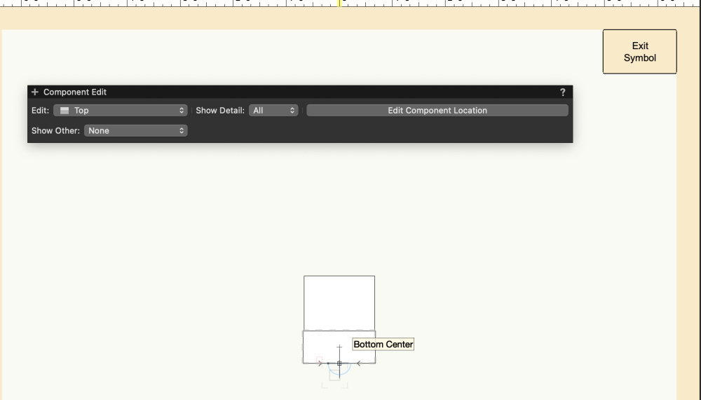
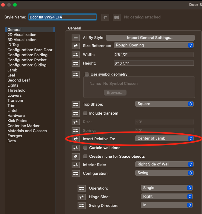
In the Door Settings, General Tab, set Insert Relative To: to Center of Jamb. That solves half the issue. I'm not sure why the door is being pushed to the left side of the wall. It doesn't do that on other walls, but I can't find the setting in your wall that causes it.
-
Hi @MartinBlomberg. I made this for theaters, but it should work for an arena: https://www.verysmallgroup.com/theaterow
-
Try this. All that line work wasn't drawn on the layer plane it was in a 3D plane. Possibly different planes. That's probably the issue auto cad was having with it. I swung everything around and set it on the layer plane. SL-001-D1-01-R0 Log Burner Planning Drawings.dwg
-
Yes. That will be in the design layer folder.
-
Attached. File is mostly empty. Convert to DWG 2.zip
-
Extract m2 and m3 per layer to (Excel)sheet
michaelk replied to RickVisser's topic in General Discussion
It is very possible to get perimeters, areas, and volumes of objects by layer in a worksheet. The question is what kind of objects you want to extract perimeters, areas, and volumes from. Do you have an example file? -
These are plug-ins written in VS in a forum about python. 😛 But I think the simple ones will translate directly. Just add vs. to the functions and throw away the variable declarations. Python IF statements are just slightly different, but I think you will be able to follow. Post back if you have questions.
-
Seeking advice on creating massing model of complex roof form
michaelk replied to Sidney Rofe's topic in Architecture
Please add your VW version and computer specs to your signature. Here's my attempt and Jonathan's better attempt in 2023. Roof Puzzle_2 v2023.vwx Roof Puzzle v2023.vwx -
Seeking advice on creating massing model of complex roof form
michaelk replied to Sidney Rofe's topic in Architecture
Here's a first stab. Someone will have a clever solution soon, but this is one idea. I made a 4:12 roof face but I made the bearing line 10 degrees off. That gets falling ridge line. Then just mirror around and use the Connect/Combine Tool. Roof Puzzle.vwx -
@spettitt I'll attach 4 simple plug-in objects. Two are examples I made for someone else for just exactly this reason. Rect Point Example and Rect Rect Example. They show two ways of making a rectangle tool. One is defined as a point object and one is defined as a rectangle object. Obviously the rectangle object is better at making rectangles. Then there is a fancier rectangle object. RK Rectangle. You should also have a 2D/3D Hybrid plug in so, I included a plug-in that gets bogged down when the object is too big. Pat's Grate 3. There is a circle of life when it comes to making your own plug-ins. You start with scripts that get more and more complicated and useful. Then when it comes time to make the jump to plug-ins, one of those who has gone before guides you through the steps and a vast universe of possibilities opens up. You realize that plug-ins are easier to write and more efficient to use. After several years of joyful plug-in creation you are horrified to learn that there is another plateau to climb: Event Aware Plug-ins. Again, a guide appears to walk you through the comically complicated steps. Then someone who is successfully and happily writing scripts asks how to make a plug-in! The circle goes on. Rect Point Example.vso Rect Rect Example.vso Pats Grate 3.vso RK Rectangle.vso
-
Editing Objects in Vectorworks Spotlight
michaelk replied to Ricky Holdman's question in Troubleshooting
That's how symbols behave. Editing one makes them all change. You will probably want to have a different symbol for each type of table layout. (Or you're welcome to try this: https://www.verysmallgroup.com/table-seating. It will make parametric tables that can each have different kinds and numbers of chairs on each side.) -
Save a custom report as a template for reuse
michaelk replied to Bobby Davidson's topic in Entertainment
That report is a worksheet and lives in the Resource Manager under Worksheets. You can import/export it between documents or just copy the worksheet on the page of one drawing and paste it into another. That will also cause the worksheet to appear in the Resource Manager of the new drawing. -
Are you dragging it in? Using the import command? Referencing?
-
Not sure how I managed to cut this section. How do I go back?
michaelk replied to arati.d's topic in Architecture
Looks like you have the Clip Cube turned on. View > Clip Cube -
@javiik I get this when I try to open your file:

-
That file was created with the student version of VW. Professional licenses can't open it. Sorry.
-
Convert to DWG 2.zip
-
Can you send me the file? Make sure you have a name in the room name field of the OIP.
-
Exporting to Old Version without Access to New Version
michaelk replied to EmilyArch's question in Troubleshooting
SchapiroTheatre v2024 v2020.vwx


