


line-weight
-
Posts
3,755 -
Joined
-
Last visited
Content Type
Profiles
Forums
Events
Articles
Marionette
Store
Posts posted by line-weight
-
-
In a further unwelcome twist to this story ... it would appear that for some reason, re-rendering a viewport, without changing the crop or anything else about it, is liable to result in a new image that is just a few pixels different in size from the previous one. So, any workflow that relies on being able to replace the old render, with the new one, in exactly the same position, gets broken.
-
I've just had one of those mornings where I've basically been doing unpaid testing for vectorworks, because that's the only way I am going to get semi-predictable results using the heliodon tool. My conclusions at the moment:
1) Just don't even think about touching any settings in the visualisation pallete when dealing with viewports. The over-rides here, for switching lights on and off, just seem completely unreliable.
2) Instead from now on I'm going to control which heliodons are on and off by class and by class only (as @Matt Overton suggests above).
3) So the heliodons are "always on" where they are sitting on whatever design layer they live on (I have a dedicated "lighting" layer). Each has its own class, and it's that class that gets turned on or off per viewport.
4) There's another bug which I don't know if it's been noted before: if you change a heliodon's class in the OIP, it doesn't actually change its class. Look in the visualisation palette, against that particular heliodon, and you'll see in the "class" column that it is still in its previous class. This caused me much confusion until I realised this, because I'd put the heliodon in the class I want, turn that class on in the viewport where I want it, but the heliodon would not be active. So, if you want to change a heliodon's class, it seems you have to activate the class, then create a new heliodon with all the same settings.
One of the biggest problems I have with heliodons is that I change the sun brightness, but it doesn't take effect, or causes unpredictable results, usually being brighter than expected. I now wonder if what has actually been happening is that there are actually duplicate heliodons active, even though the vis palette says there are not. Anyway, I'm now implementing a strict "by class only policy" and will see if this helps at all.
-
 1
1
-
-
There are so many bugs with the Heliodon tool, it's hard to know which one is causing a problem at any one time.
-
Does anyone else have this problem all the time?
It seems that if you change the "sun brightness" setting of a heliodon, whether that actually takes effect is highly unreliable.
I can do a rendering with it set at 100%, then change it to 50%, redo the rendering, and sometimes I'll see a difference and sometimes I won't.
I can't work out a consistent way of getting around it: making a new heliodon and changing the setting on that? Duplicating the heliodon and then changing the setting? Closing and opening the file? Quitting and reopening Vectorworks?
Is there something somewhere I might be missing?
-
19 hours ago, Kevin Allen said:
Maybe change to a middle gray solid color?
I'm not sure which setting you mean?
-
Yes. At the moment I'm doing something slightly complicated that involves exporting a large number of renders that need to be an exact pixel size for a website.
All I need is to be able to right click on the viewport and extract what I know VW can produce (because it produces it if you do cmd-K on the veiwport).
I can't really use the exact-size sheet method you describe because the number of viewports, and I want them on the same sheet so that I can transfer class settings and other stuff easily.
Doing a copy-to-clipboard nearly works but it adds a white border, and something weird happens to the resolution which is then a big faff to sort out in an image editor.
I did some experiments to see if there was a sheet resolution that would produce output from the marquee tool that was the same pixel dimensions as VW had actually rendered. It turns out it would have to be something like 92.26dpi, and the sheet settings only accept whole numbers. If I try with 92 or 93 dpi, the marquee tool gives me an image that is just a few pixels larger or smaller than the actual rendering, so it must resample it somehow and this must result in a loss of image quality.
The saviour is the great script produced by @herbieherb which can be found here. That gives me something reliable and predictable (and also allows me to batch export a bunch of images, already named correctly if I give the viewports names). Unfortunately it doesn't export anything on an annotation layer though.
So it looks like my workflow is going to have to be
-Export from VW using that script
-Open in an image editing programme, and do all my annotations on layers in there
-Export from there to produce the final output
The whole step of messing around in an image editor could be avoided if VW could just provide a very simple command, which we know would be technically possible to implement, and which was requested at least five years ago.
-
1
-
-
6 hours ago, Pat Stanford said:
the conversion from 1,000,000 mm3 = 1 m3 for you.
It's 1,000,000,000 mm3 = 1 m3!
-
On 3/4/2015 at 3:38 PM, PVA - Jim said:
Confirmed.
You'll note on either a sheet layer or design layer, if you set the page to say, 8x11, if you do a marquee export and snap to the corners of the page area, when the image export box pops back up it claims the image size is significantly smaller than 8x11, im even seeing 4x5 in some tests. If you try to set it to pixel dimensions, you'll notice that the pixels reported by the marquee UI dont even come close to matching the pixel dimensions in the dialog afterwards, which leads to way lower quality than you might expect.
One of the other techs here submitted this as a bug, but I'm adding this thread and some new info to it. This did not occur in previous versions.
Just dropping by, FIVE YEARS LATER to note that this bug is still not fixed, in VW2018 or 2019. I don't have 2020 yet. Don't know if anyone can confirm whether it's still an issue there? I'll put my money on it not being fixed.
-
1
-
-
1 hour ago, Tamsin Slatter said:
Absorption distance is the setting that gives darker effects on glass when it's viewed from different angles. Have a look at that setting. If you change it to zero you may be able to remove the effect you're seeing on the fillets.
Thanks. It's already set to zero on that texture (the top one of my images), though.
-
Thanks! Yes, I have tried playing with these settings a bit, but without full understanding of what they each do. I was hoping someone might be able to point me to the specific things that will affect what I'm trying to change ... otherwise it is quite a long and tedious process of trial and error.
-
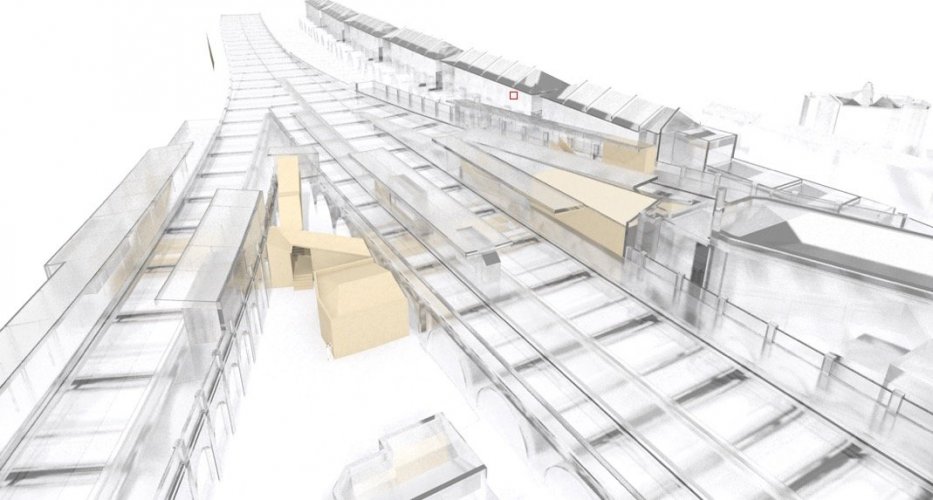
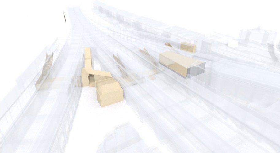
Here are some test renderings for quite a complicated model.
You can see that there is a bunch of stuff that I am rendering as if it's glass - the idea being that the parts that I've highlighted in a kind of beige colour are visible through it.
In the top image, I've used the "glass frosted 01 RT" default texture. It sort of looks how I want it, but I'd like to reduce the very dark portions that mostly appear along edges, but also on some angled faces. What's the setting that I should be fiddling with to reduce this? Are they reflections? If so, I can't work out what they are reflecting, because I've got a pure white background.
The bottom image is the same model but using "plastic transparent polythene RT" instead. This has no dark edges, and makes the highlighted elements more visible, but I don't like the look of it so much - it doesn't really look like a real material. So I guess I'm aiming for something that is in between these two materials.
Any tips?
-
It's scientific notation (E notation)
https://www.calculatorsoup.com/calculators/math/scientific-notation-converter.php
7.59e+006 means 7.59 x 10^6 (10 to the power of 6 which means 10 with 6 zeros after it)
So, 7.59 x 10,000,000 = 7,590,000mm3
Then you can use a converter to change it to cubic meters or whatever unit you need.
eg
https://www.digitaldutch.com/unitconverter/volume
Somewhere in vectorworks there is a setting that will make you give these volumes in, say cubic metres rather than cubic millimetres, if that's more useful to you. I think.
-
1
-
-
39 minutes ago, Andy Broomell said:
Hmm, good question. I’m not sure about individual Light overrides from the Visualization Palette. My guess is no?
I typically only turn entire systems of light on or off by putting the Lights on classes and making those classes visible or invisible.
The eyedropper definitely does copy “Lighting Options” along with Foreground/Background render settings. But let us know what you find out about Light overrides.
A quick test suggests that it does pick up light overrides if the "render properties" box is ticked.
That's potentially handy - although, could also be problematic where I want to copy render settings between viewports without changing the lighting setup.
In that case, I guess I could use your class based system for switching lights - but then I'd have problems where I want to copy class visibilities but leave the lighting alone.
A typical use case for me is when I do sunlight studies - I'll have maybe an option A and an option B design, and for each one I'll have a few viewports showing sunlight at different times of day/year, which I do by having multiple Heliodons, each for a different time, and each viewport will have one of these switched on.
-
That's me not looking carefully enough!
Does that copy lighting settings too (ie which lights are switched on or off)?
-
I've a feeling I've seen this as a wishlist item at some point ... but it would be useful if the eyedropper tool could copy render and lighting settings between viewports too.
-
Ah! I never noticed it had these settings! This will make quite a few things easier. Thanks.
-
Is there any way to copy class visibilities only from one viewport to the other?
-
I've realised there's a problem: a saved view can have the "don't change" option for class visibilities, whereas a viewport can't.
This means that the method described above doesn't work for any saved views where I have some classes set as "don't change" - that setting gets over-written.
-
5 minutes ago, markdd said:
Or go to the old saved view. Activate the new saved view of classes only and then select the Old saved view in the Navigation Palette and select Redefine.
Yes, that's pretty much what I mean.
-
I've had a thought though, maybe this can be a multi step process:
1) Edit viewport>display using viewport visibilities
2) Save that as a temporary saved view.... but save the class visibilities only.
3) Go to the saved view that I want to change (with layers and other stuff set up)
4) Then go to the temporary saved view, which will switch the classes but leave everything else alone
5) Then save that on top of the old saved view, effectively changing it to the new class visibilities setup.
A bit tedious but less tedious than manually changing lots of class visibilities.
Not sure if something similar can work in the opposite direction.
-
10 minutes ago, markdd said:
Just a suggestion. If you were to Edit the Viewport and select Design Layers and then check Display Using Viewport Visibilities. You will get to the design layer where you can save a View with just the class parameters selected. I guess it won't work with Class overrides though if that is your need as well.
Mark
Thanks.
Yes, this would allow me to save a new saved view, with the right classes activated.
However, ideally I want to be able to copy the class visibilities to saved views that I already have set up with specific viewpoints, render modes, layer visibilities etc.
Class overrides (which i do use in the viewports) would not be a problem, because I don't need the overrides in the saved views.
-
1
-
-
I have some viewports set up with a rather complex bunch of class visibilities - and I also have some saved views set up with similarly complex bunches of class visibilities.
Is there any way I can copy the class visibilities (and the class visibilities only - not anything else) from a viewport to a saved view, and/or vice versa? Ideally a way that doesn't melt my brain in the process?
-
 1
1
-
-
On 5/26/2020 at 8:51 PM, Jim Smith said:
Not to beat a dead horse, but sheesh! Why are there two systems that don't make ANY sense for sizing stuff that should be identical?
The font size in both instances are 6 point. A marker size of 4 produces a circle of 600mm or 4mm on the page for the Detail Callout that's generated from a Detail Viewport, but a Reference Marker Detail Callout is completely different with a 2D detail scale factor of 0.6.
Also while I appreciate being able to change the Font size from the Font menu, seem like one should also be able to choose the font size in the OIP no?
Here are the graphic output for a Detail Call out:
.thumb.png.9469402407cb33080d4ac2f0d255c4e4.png)
.thumb.png.121c0bf73461299531c5ccf60d18723f.png)
Now here are the details for a Reference Marker Detail Callout object:
.thumb.png.733e9e0a12a0a1478859f23c6f578bef.png)
.thumb.png.c0b1018ef3ac51ba563d8115c40251bb.png)
Totally agree with you. Have lost any hope that these kind of things will be addressed any time soon though. Instead they'll introduce another kind of marker with yet another slightly different way of setting the parameters.
Most of those marker objects are also a nightmare to edit graphically, partly due to inconsistencies in behaviour between outwardly similar objects.
-
2
-
-
11 hours ago, Pat Stanford said:
OK, the following script will change the projection to Normal Perspective and the Render Mode to Open GL.
If you go to Tools:Plug-ins...:Plug-in Manager and then to 3rd Party you can create a new Plug-in Command, click the Edit Script button and paste the script below into the window.
Then edit your workspace to add the command and give it a keyboard shortcut.
If you really wanted to get fancy we can add the view to change to as well, but you would have to have different versions for each different view. I don't think you can over-ride the keypad view commands or it would be kind of nifty to be able to hit (say) Option-1 on the keypad and get it to switch the view and change the render mode.
For now you will have to change the view and then run the script.
Procedure OpenGLandPerspective;

{May 25, 2020}
{©2020 Patrick Stanford pat@coviana.com}
{Licensed under the GNU Lesser General Public License}

{No Warranty Expressed of Implied. Use at your own risk.}

Begin
	DoMenuTextByName('Projection',5);
	DoMenuTextByName('OpenGL Render Chunk', 1);
End;

Run(OpenGLandPerspective);
Thank you for this - very kind of you!
I've set it up (I'm currently on 2018)
It works perfectly when I'm within a group - which is great. This will be very useful.
When I run it outside of a group though I find that it first changes the projection to perspective, but I have to run it a second time to get it to change to OpenGL. This is not too much of a big deal as it's quite easy to just hit the shortcut button twice.
Would it be straightforward to make it change the view as well? If it could also change to, say, left isometric that would be really helpful. I don't atually mind which direction the view is; what's more important is that I can see what's going on in 3d, and I can then easily fly around to the angle I want, if it's different.


.png.9bbf3261f6d3d092238804fc7019cbd2.png)
.png.08d55042ab04f4060f3050700c5852e9.png)
.png.c4f9e069b0810a52b8e2306e7d1ae112.png)
.png.5b04d1709fe54a604023b30889cae6b2.png)
Rendering glassy materials - dark edges
in Rendering
Posted
Trying that doesn't seem to make much difference - you may have misunderstood what I'm trying to reduce, which is the dark grey/black you can see along the 'edges' and facets of some the glassy elements. Here I have highlighted a couple of examples: