line-weight
-
Posts
3,757 -
Joined
-
Last visited
Content Type
Profiles
Forums
Events
Articles
Marionette
Store
Everything posted by line-weight
-
Kind of a separate issue fro what this thread is about... but I think that I'm right to say that if you have multiple-component walls, those junctions between two walls of different heights are going to be a mess (if you want the components to join properly in top-plan or plan section view). This is one of the things that VW seems to fail to deal with well. You end up having to do it with multiple bits of wall stacked on each other, or similar.
-
I quite like to work in 3d view as much as possible, therefore the way I often rotate things is to set the working plane perpendicular to the axis of rotation (in this case I have taken the working plane from the end face of the wall) and then use the rotate tool. (boh's method may be easiest to use if you are new to VW though) In fact the extrude doesn't need to be on a different layer from the wall, for the "fit walls to roof" command.
-
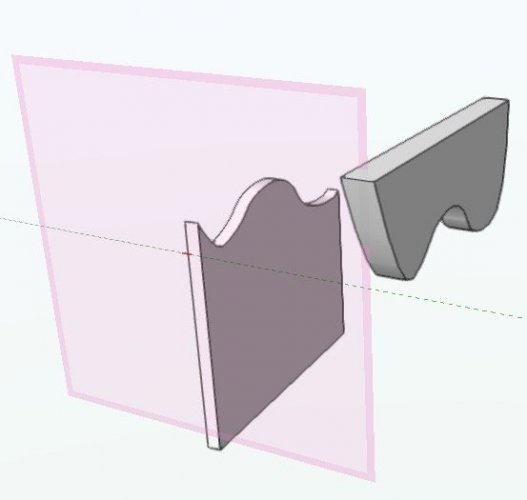
You have to carefully follow the instructions given by @cberg above, where the "fit walls to objects" command is mentioned. You have to make the extrude the opposite of the shape you want to end up with. You then "fit" the wall to that object to end up with the right shape. Think of it a bit like subtracting the extrude from the wall. This video explains that command. Usually it's used to make the top edge of a wall follow the underside of a roof shape. In your case you want to make it follow the underside of your template extrude object.
-
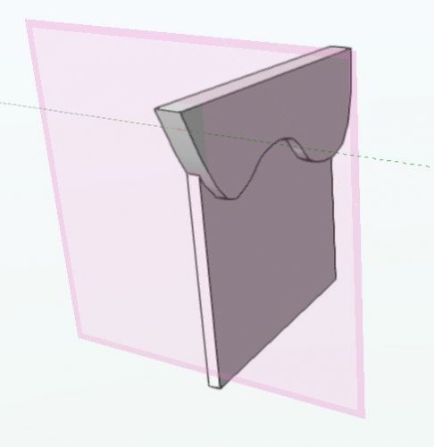
Based on the selection handles, it doesn't look like you have a wall object there - it looks like an extruded solid. Is that what you intended? If it is just an extruded solid, then VW does not understand that it is a 'wall' and therefore it won't connect with the other walls or take on their fill, when you are viewing it in 'top/plan' view.
-
I am currently having exact same problem in VW2018. Just one slab at the moment.
-

Determine roof face slope from existing geometry?
line-weight replied to line-weight's topic in Architecture
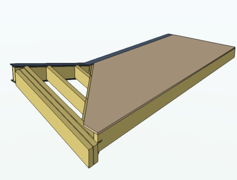
Yes. Also, I'd like to be able to extend/pull back individual roof layers on individual edges like you can with the floor slab tool. The wall, slab and roof face tools are all a similar concept: a buildup with multiple layers. Ideally the way of editing each of them would be the same (in fact I'd argue they could all be the same thing: a "multilayer object" if you will, and you choose whether it's horizontal, vertical or sloping). -
Determine roof face slope from existing geometry?
line-weight replied to line-weight's topic in Architecture
@Alan Woodwell Yes that is what I'd usually do. In this instance though, the question is specifically about the capabilities of the roof face tool. -
Determine roof face slope from existing geometry?
line-weight replied to line-weight's topic in Architecture
Yes! -
Determine roof face slope from existing geometry?
line-weight replied to line-weight's topic in Architecture
Oh well, it seems this is what has to be done. I'll get an angle that will be 12.527 degrees or something... and apply that, but then feel that it might not quite exactly match because of a rounding error somewhere. -
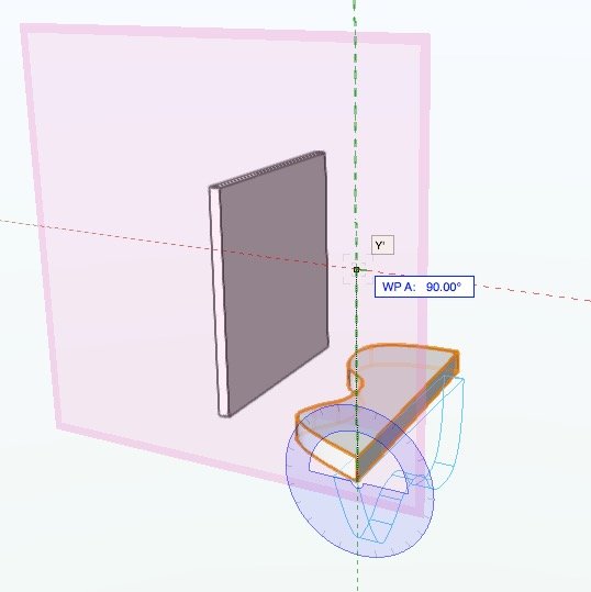
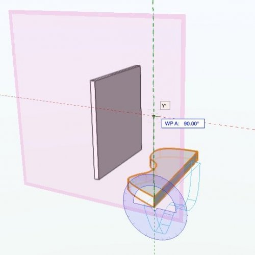
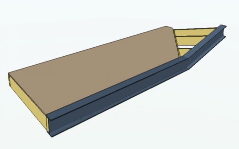
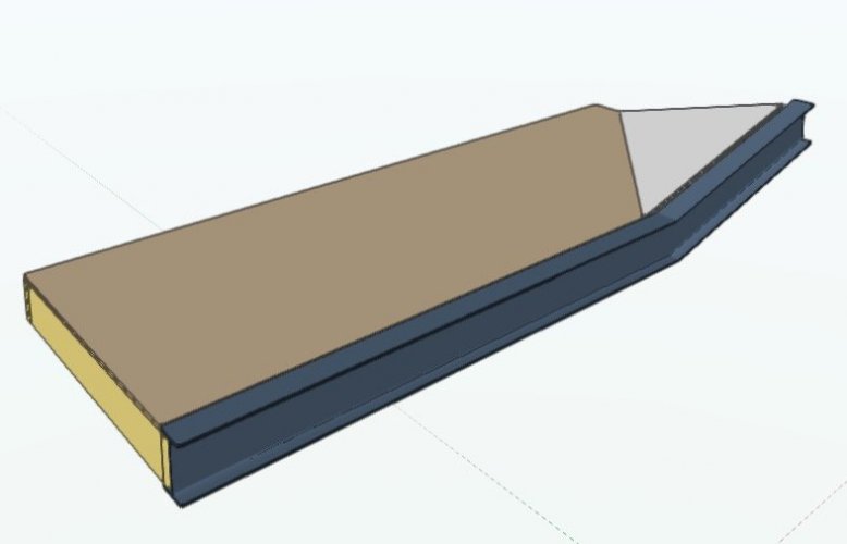
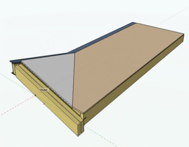
I'm fiddling about with roof face objects; haven't really used them much before. See the attached screenshots. The brown coloured slab is horizontal. The white coloured slab is the one I'm trying to make as a roof face. The plane of the white slab is determined by the geometry that's already drawn. If I were drawing it as an extrude, I would set the working plane by three clicks on the relevant edges of the joists you can see. So, the plane is pulled directly from the existing geometry and I know it should match exactly. To make the roof face, I could draw the profile accurately in plan, and I could set the axis accurately (the axis can be generated by intersecting an extrude, drawn as described above, with the horizontal slab object). However, to set the 'pitch' of the roof face object, I did it 'manually' (basically eyeballing it and adjusting the rise/run dimensions until it was correct). That's not ideal. Any clever ways to do it accurately? Do I have to do something like set the working plane, draw a line on it, find the angle of that line, copy and paste that angle into the roof settings? Still feels a bit messy.

-
This question illustrates the inadequacies of the wall tool. It shouldn't be necessary to go through the convoluted process of making an extrude that's the inverse of the shape you want. (That function is obviously designed to quickly shape walls to the underside of roofs etc - but people use it for situations such as described in this thread because there's not another way to do it.) It should be possible to tell VW to make a wall to the shape of a polygon or other 2d shape that you can draw accurately, a bit like an extrude. Of course this would still not solve the problem of what happens when two walls with different heights meet at a corner as is the case in the OP's design - gets very messy if the wall has more than one component. All this is why I often end up modelling everything as 3D solids (and have stopped using top/plan)
-
This is the part of making models/renders I find the most painful too... also because many imported furniture items come in in way too much detail, and then you either have to spend time simplifying them, or find ways to stop them making your model become completely unmanageable and slow.
- 31 replies
-
- 1
-

-
- renderworks
- rendering
- (and 1 more)
-
I can, but... In the past, a bug uncovered here on the forums would be picked up and submitted by JimW. Is there no-one at VW who will take over this function from now on? Doing a bug submit requires me to fill out a tedious form. The issue is explained by reading this thread so I don't feel hugely inclined to spend more of my time duplicating information that's already available.
-
CAST WYSIWYG PERFORM user struggling with simple things in VW
line-weight replied to BradLyons's topic in General Discussion
VW has a long history as a 2d drafting programme, and is being dragged into the 3d world a little painfully. Lots of the stuff (principles of classing and so on) that worked well in 2d, and which has always made it a very flexible software, transfer into a 3d context in a way that means it remains very flexible, but behaves in a rather different way from what people expect, if they've come from software which started out as kind of object-based plug&play 3d environment. Or, that's how I see it. If you want to model non-standard stuff, and/or set up your drawings in a way that is optimised to your particular workflow, then VW gives you pretty impressive scope to do this, and remains one of its great strengths. However, it does mean that to some extent there's not really a 'standard' way of doing things, and this can make it pretty confusing for new users I think. It also means (as far as I can make out) that it is tricky to make foolproof parametric-type objects that 'just work' in the way you describe. There will always be some setting or something, that means something isn't quite doing what you want, and it takes a while to work out what it is and where it is, and this can be very frustrating, but at the same time, this customisability is what allows it to be so flexible, and quite powerful once you actually get a grasp on what's going on. But aside from - or alongside - all this, it's true that many of VW's tools/parametric objects are pretty poor. In some cases they haven't been updated for many versions and you only realise that they don't work for certain things once you've spent some time getting to understand them. I don't do lighting design so am not sure to what extent that applies in that part of the programme, but many of the architectural tools (things like stairs and windows) are very poor and in urgent need of update. I think those tools are now well left behind by their equivalents in other architectural packages, perhaps similar to what you describe, but then those other architectural packages perhaps don't allow the flexibility that VW does (again perhaps similar to what you describe when comparing to the other software you use). -
Extents above Cut Plane - Clean wall outline
line-weight replied to drelARCH's topic in General Discussion
Is this a normal section viewport? How are you getting those dotted lines to show in the first place? -
The frame corners are not a problem, I was just noting their absence in the one that wasn't working. As it happens in both cases they were in perspective view. Unfortunately the type of view I'd mainly like to use this in would be section viewports...and it seem it doesn't work for them.
-
I can get it to work in 2018, if I make a very simple test file. However I can't get it to work on one of my 'real' drawings. In the test file, little frame corners appear on the viewport crop object when I use the translate tool. This doesn't happen in the 'real' file. **edit - I think it might be to do with multiple view panes. When I created a floating pane in the test file, it stopped working.
-
I think this is something that is supposed to work in a 3d view? (Didn't know this until now - not that I can actually get it to work so far) But I'm actually thinking of section and elevation viewports.
-
At the moment (unless I'm missing something) it's a right palaver if you want to move the contents of a cropped viewport, whilst keeping the viewport in the same place on the sheet. Typical scenario: you have a zoomed-in detail of a floor/wall junction. A change to the design means the floor changes to a lower level, but the detail of the junction remains the same. Lowering the floor in the model means that the relevant junction now sits outside of the viewport crop (and is not in line with any relevant annotations). To remedy this you have to: 1) Go into crop edit mode, and move the crop object so that it's in the right place relative to the model view. 2) Exit crop mode. The viewport is now in the wrong place on the sheet. 3) Move the viewport back to its correct place on the sheet. 4) Go into annotation edit mode, and move the annotations back to where they should be relative to the viewport content. 5) Exit annotation mode and hopefully you are now done, unless there are several other viewports that need the same treatment for the same reason. It would be much simpler if there was an edit mode where the crop object and annotations remain locked to their position relative to the sheet, and you can then move the viewport content around, to bring it back into the crop area, and back into alignment with the annotations, in one go. A one step process.
-
Can I stop VW re-rendering everything on PDF export?
line-weight replied to line-weight's question in Troubleshooting
It doesn't help with this particular problem - which is when VW starts to re-render viewports that you don't want/need to be re-rendered. -
Can I stop VW re-rendering everything on PDF export?
line-weight replied to line-weight's question in Troubleshooting
Same applies if you use the print dialogue, either to print to paper or PDF. The "update visible out of date viewports prior to printing" is ticked by default.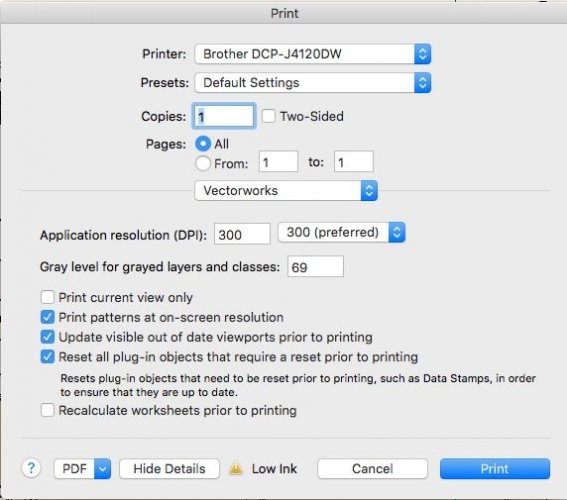
-
Around 2025 perhaps.
-
Can I stop VW re-rendering everything on PDF export?
line-weight replied to line-weight's question in Troubleshooting
I think a global setting. If you accidentally have it "off" when actually you want it on, all it takes is a couple of mouse clicks to sort. But if you accidentally have it "on" when actually you want it off, the price is either an extended wait for everything to re-render (can be a *very* long wait if you've got several renderworks viewports on the sheet layer) or forcing VW to quit, possibly losing some work, but also with a time penalty of waiting for everything to reboot, and possibly then re-rendering the viewports that you had ready to go and were just about to export. Another solution would just be to have the option to cancel the publish/export process once it's begun. -
Can I stop VW re-rendering everything on PDF export?
line-weight replied to line-weight's question in Troubleshooting
Not that I've been able to find, unfortunately. -
Can I stop VW re-rendering everything on PDF export?
line-weight replied to line-weight's question in Troubleshooting
Yes, you have to remember to check it every time. It defaults to being activated - I'd like the default to be not activated.