line-weight
-
Posts
3,755 -
Joined
-
Last visited
Content Type
Profiles
Forums
Events
Articles
Marionette
Store
Everything posted by line-weight
-
 Well, it looks to me like the answer to this wishlist item is that there is an outright refusal to acknowledge the value of a dedicated forum moderator, and we're not going to get one. A very short-sighted decision in my opinion.
 -
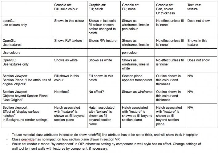
Here's the table I made for myself last time I was trying to figure out how all this works (I find it very confusing). May not help, but just to let you know you're not the only one that struggles with this stuff
-
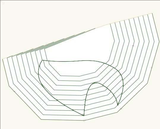
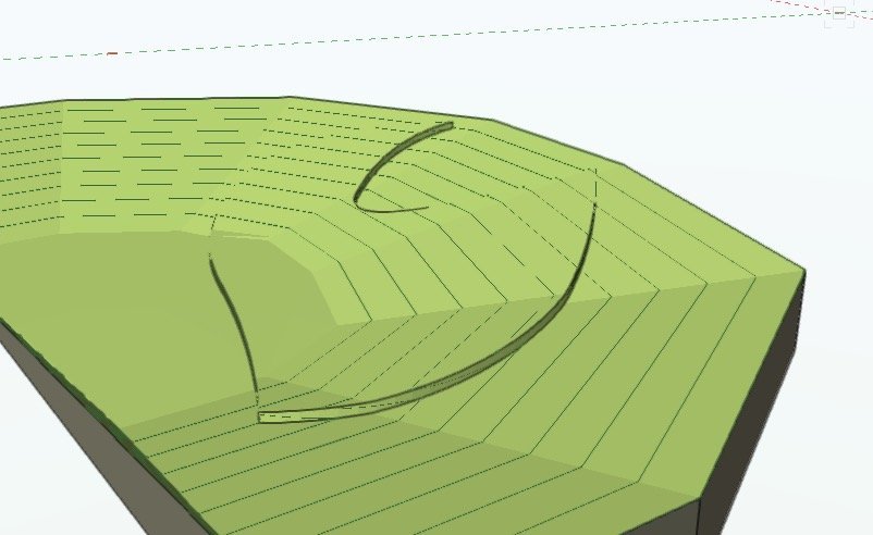
Agreed on all the limitations. Previously my system to create a slightly raised area (typically pavements/sidewalks along roads) was to do an extrude of the shape in plan, solids-intersect with the site model object, then raise it slighty. Rather messy. Using the spoil pile means that it doesn't have to be laboriously redrawn each time there's a change to the underlying site model or to the shape of the raised (or lowered) area. Unofortunately it doesn't leave much scope for modelling things like dropped kerbs. In my opinion the single most useful addition to the site modifiers would be a 'vertical edge' modifier. You'd draw a line, specify it was X height, and the ground on one side of it would be X higher than on the other side of it. It could be a closed shape or an open line with a taper back to level at each end.
-
Extrude Along Path - why's my wall leaning over?
line-weight replied to line-weight's question in Troubleshooting
When I mentioned the special working plane, that's only if you want to edit the profile retrospectively (ie after you've done the EAP). Yes, I noted this same problem. Could be troublesome if you need to do something very precise. -
I've ended up at this thread whilst trying to solve similar problem for myself. But if it's just a portion of the site model to be extruded up from the underlying surface... doesn't the "spoil pile" modifier do the job?
-
Extrude Along Path - why's my wall leaning over?
line-weight replied to line-weight's question in Troubleshooting
*FRANTIC WAVING AT VW STAFF* Is anyone from Vectorworks reading this? The EAP command needs proper documentation. If this was all explained properly in the documentation it would save me and others spending literally hours working stuff out by trial and error when there should be no need to do so. This was already requested in a thread in 2017, two years ago, the one I link to in the post above. As well as the one I posted a couple of days ago which no-one from VW has responded to. -
Extrude Along Path - why's my wall leaning over?
line-weight replied to line-weight's question in Troubleshooting
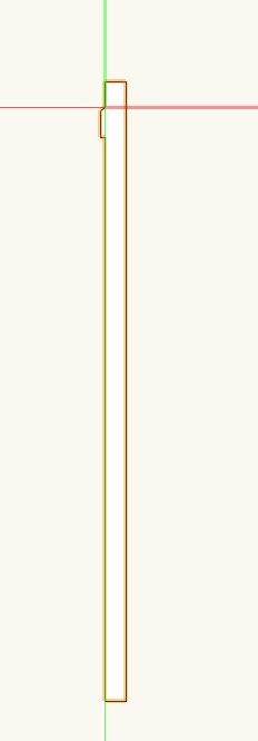
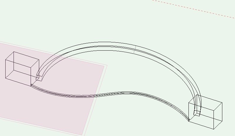
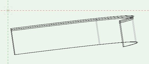
Ok, after a certain amount of testing, and also following some clues I found in this useful thread on a similar subject: https://forum.vectorworks.net/index.php?/topic/52320-extrude-along-path-rotation/ I think I have found how to make it do what I want. 1) The profile must be a 3d object (3d polygon or NURBS curve seem to work) 2) The profile must be oriented in 3d space, as you want it. So it must be placed so that anything you want vertical is vertical. And it must be placed how you want it relative to the normal at the start point of your path viewed in plan (ie its rotation in plan is relevant) 3) When you preform the EAP command, "Lock profile plane" and "fix profile" must both be ticked 4) Now if you're lucky it'll produce what you want 5) Now (and I think this is a result of ticking "fix profile") when you edit the profile, instead of being taken to a top/plan view of the profile you are taken to a top/plan view of the path with the path greyed out and the profile also viewed from the top. The origin of this view seems to be the start point of the path, and you can move and rotate the profile relative to this. To edit the profile, you have to edit it as a 3d object. In my case, to alter the profile, this meant setting a working plane on the plane of the profile, then looking at this plane. Here is an example file Untitled 1.vwx Here's the EAP viewed in plan and in elevation Having thinking that I've worked this out, some problem will probably arise now that I try and use it for real, but let's see...
-
Extrude Along Path - why's my wall leaning over?
line-weight replied to line-weight's question in Troubleshooting
Thank you for your reply @Benson Shaw and your suggested workarounds. Not sure if this counts as a bug? Anyone from VW want to comment? This is not unrelated to my other thread (linked below) where I am pointing out that the documentation of EAP is insufficient. And this is such a familiar scenario in VW - I've not used EAP that much in the past, but thought I'd try and get my head around it. So I invest a load of time trying to understand how it works, and the answer is that it doesn't work properly. Like so many other things in VW. As you say - sigh. -
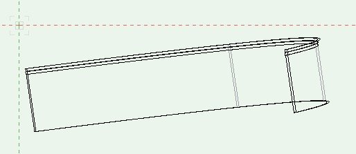
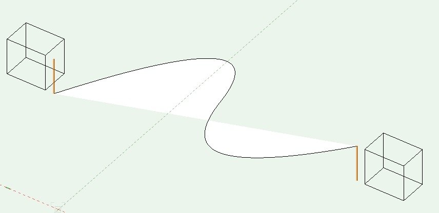
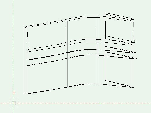
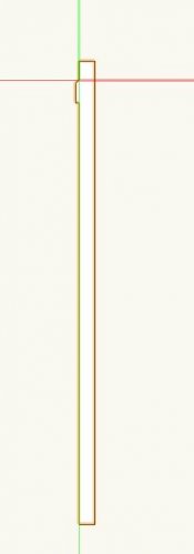
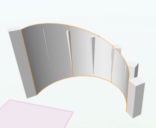
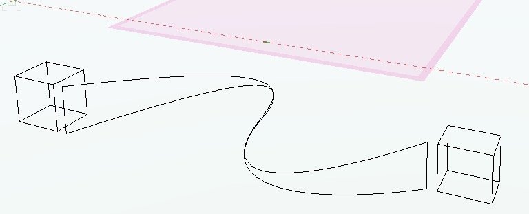
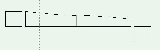
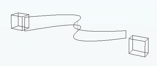
Both of the EAPs in the attached file are supposed to be walls, which follow a 3d path (curving in plan and changing in elevation along their length). I have 'lock profile plane' ticked. My understanding was that this means that the profile remains perpendicular to the X-Y plane as it follows the path (thus creating a vertical wall that doesn't lean over). This is not what's happening though. Am I doing something wrong? Profile: resulting EAP viewed in elevation: VW2018 file: Untitled 23.vwx Untitled 23.vwx
-
3d point clouds - need to rethink
line-weight replied to digitalcarbon's topic in General Discussion
@digitalcarbon I'd be interested to know how useful that point cloud in image 1 really turns out to be. I don't know exactly what data you need and for what, but looking at your survey notes it seems you want something reasonably accurate and detailed. My guess is there will be lots of visits back with a tape measure, that take up as much time as it would have taken just to do it the 'old skool' way from the start. Plus a bunch of fiddling around to convert everything into objects that are actually meaningful to VW. -
Controlling visibility using data visualisation
line-weight replied to line-weight's topic in General Discussion
Ok, yes I had it set on OpenGL. Switching to wireframe sort of fixes it, but it seems i have to switch wireframe->openGL->wireframe to get it to update properly, so there's obviously something buggy going on. When I do a 'fast external' renderworks style I get the black holes like your image above. -
Extrude Along Path - missing info from documentation
line-weight replied to line-weight's topic in General Discussion
Is anyone from VW reading this? My questions above highlight information that is not provided in the vectorworks help documentation. I think the documentation needs to properly explain how to use the software. There are relatively basic aspects of the "extrude along path" command that are simply not explained. -
How to set an even or smooth gradient on a nurbs curve
line-weight replied to line-weight's topic in General Discussion
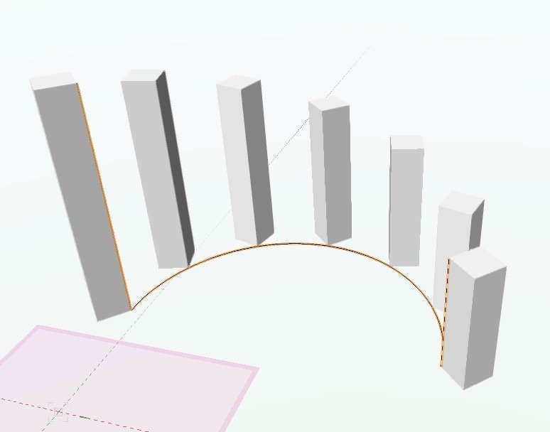
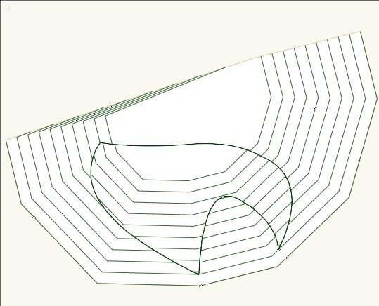
However: here I think is proof that the loft tool unfortunately can't do what I want. The extruded squares are a duplicate array, so the distance between them is equal. The NURBS curve that will become the 'profile curve' is drawn with control points on each of the bottom corners of the extrudes, as shown. So the distances between control points are equal. The extrudes step down in height by an equal amount. So if the 'top slope' of my loft object is to have a constant gradient then it should be passing exactly through the top corner of each of the extrudes. But this is what happens: There are actually two problems: 1. The gradient is not constant 2. The top line is not directly above the base line...in other words, if it is a wall then it is leaning over.
-
How to set an even or smooth gradient on a nurbs curve
line-weight replied to line-weight's topic in General Discussion
Actually I have edited the post above - it was my mistake, the base was not supposed to have a slope. -
Controlling visibility using data visualisation
line-weight replied to line-weight's topic in General Discussion
Yes, I think the problem with this would be that you couldn't work on the model in the design layer because everything would be invisible. This raises a problem with other solutions using record formats though, including the one with @Pat Stanford's script above: in the model, some 'sites' will have more than one building on them - they'll have eg the building that existed from 1870 to 1955, and the building that existed from 1960 to 1991 on them. So if you are looking at the model with 'everything on' then they are both going to be there, drawn on top of each other. If they are in different classes that's fine because you can just turn off the classes as appropriate whilst looking at the design layer. In VW2018, I don't think there is a way of making things invisible in the design layer bases on their record format data, but perhaps the changes to DV in VW2020 mean that there now is? -
Controlling visibility using data visualisation
line-weight replied to line-weight's topic in General Discussion
Thanks again for taking the time to do this. I've looked at the file. Changing the date using your script doesn't change the object visibilities in that viewport, I'm not sure why* I think I understand the logic though: the script looks at the build and demo date for each object and then sets the other record to 'true' or 'false' according to the requested date. Then the viewport DV uses that value to decide whether or not to display the object. This means it wouldn't work if I wanted several viewports, each showing the state of existence at a different date. But I think you are suggesting that this could be dealt with by having a 'true/false' field for each desired year. So the record could have a bunch of true/false fields called "exists in 1955", "exists in 1970", "exists in 1991" etc. And the script would populate some/all/none of those fields as necessary. * When I look at the viewport DV settings in your file, for the 'Data Visualisation-4' viewport, I notice: - 'Enable Data Visualisation for This Viewport' is not ticked (I think it should be?) - It's set to 'Record Field': Build (I think it should be set to Record Field: Year) - Under Record Field: Year, in the values list, 'False' is set to show with pen/line thickness (I think it should be set to fill=none and pen=none) Having changed the above, it still didn't work. The script does seem to tick/untick the true/false box correctly (when I look at the objects on the design layer), but somehow the DV is not doing what it should. -
Controlling visibility using data visualisation
line-weight replied to line-weight's topic in General Discussion
Thanks for that - I'm still on 2018 I'm afraid (sorry) -
How to set an even or smooth gradient on a nurbs curve
line-weight replied to line-weight's topic in General Discussion
Hrm. Here is what happens with a more complex curve. It's pretty clear it's not giving me a constant gradient. The top image is an elevational view. *Edit - ignore this post! I messed up by accidentally not drawing my curve on one plane. Hence the bottom is not flat.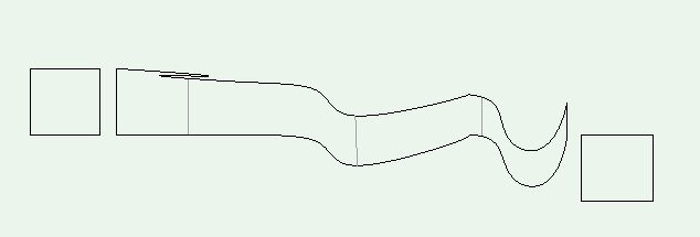

-
How to set an even or smooth gradient on a nurbs curve
line-weight replied to line-weight's topic in General Discussion
Ok. Got it to work after some fiddling. Being fussy though - when I look at in orthogonal elevation, I can tell the gradient isn't constant because it actually goes upwards very briefly around the middle. In both of the variants below. Maybe this is something that would disappear if the NURBS curve had more control points?
-
Controlling visibility using data visualisation
line-weight replied to line-weight's topic in General Discussion
Thanks @JMR! I think I get what you are doing there, 'hiding' some objects by colouring them in white in an overlay viewport. Interesting, but doesn't quite achieve what I need. (I need the non-visible buildings to be totally disappeared) -
How to set an even or smooth gradient on a nurbs curve
line-weight replied to line-weight's topic in General Discussion
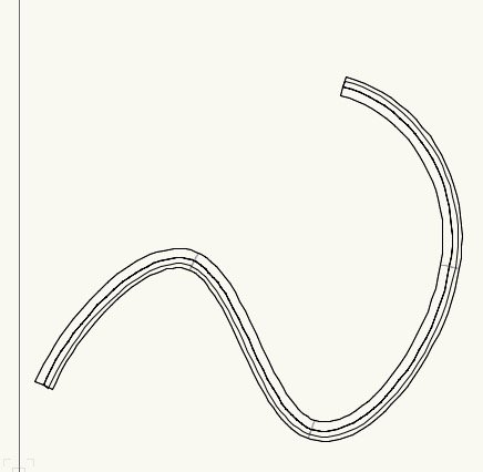
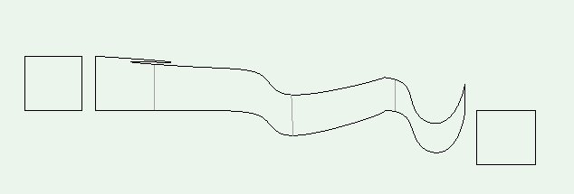
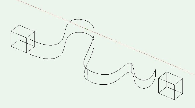
Do you mean like this (the lines highlighted in orange are the two 'rails', the wavy line is the profile) When I try and perform a birail sweep, it will let me select the two lines but not the profile.
-
How to set an even or smooth gradient on a nurbs curve
line-weight replied to line-weight's topic in General Discussion
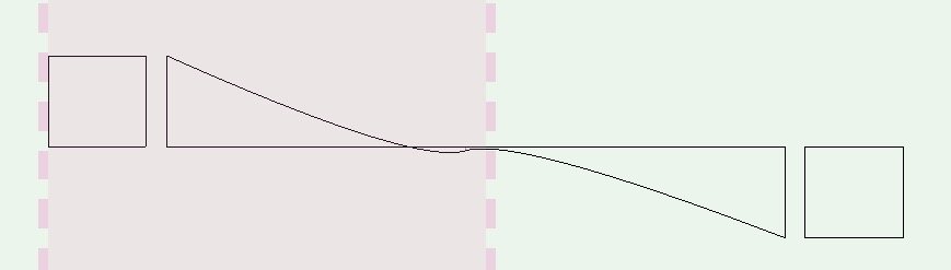
Thanks - but that has the same issue - the gradient of the curve is not constant, measured along the curve. To make the extreme example - I've drawn the large arc on the same working plane as your S-curve, but the top bit of that arc is not going to be on a downward gradient (in fact it will go slightly uphill at the start).
-
Extrude Along Path - missing info from documentation
line-weight replied to line-weight's topic in General Discussion
Thanks @EAlexander That gets me some of the way but some things remain unexplained. So, if I draw the profile in top-plan view, with 'fix profile' unticked, then it'll just follow the path with VW taking its centre as the reference point, which I can adjust retrospectively. That's clear. But if I draw the profile on a 3d plane, again with 'fix profile' unticked, then sometimes it works, sometimes it doesn't. (Trial and error: it seems happy with a polygon path but not a polyline path. Why?) Now with 'fix profile' ticked: If I draw the profile with one of its corners exactly on the start of the path, it goes as expected. If I then move the profile away, so that the start of the path is on the plane of the profile, it still goes as expected. What if I move the profile somewhere else in 3d space, where the start of the path is not on the plane of the profile? Sometimes it works and sometimes it doesn't. What are the criteria for it working? Must the path intersect the plane of the profile? Is it that intersection point that now determines where the extrusion appears relative to the path? I can seem to get it to work at all with 'fix profile' ticked and a polyline (or nurbs curve) as the path. Is that expected behaviour? -
How to set an even or smooth gradient on a nurbs curve
line-weight replied to line-weight's topic in General Discussion
Unfortunately I'm on 2018 here so can't open your example file... -
How to set an even or smooth gradient on a nurbs curve
line-weight replied to line-weight's topic in General Discussion
That might give a near-enough-right result ... but wouldn't be geometrically correct in terms of a constant gradient along the path, because of the curve in plan (the gradient would be steeper in the middle than at each end). I think.