


line-weight
-
Posts
3,756 -
Joined
-
Last visited
Content Type
Profiles
Forums
Events
Articles
Marionette
Store
Posts posted by line-weight
-
-
10 hours ago, bob cleaver said:
After dissecting the file (thank you for sharing) I need to learn more about subdivisions
Your approach is very much like construction methods (especially the plum bob symbols)
Hopefully youtube will be a resource
Same here.
-
It's the site modifiers that are causing the problem. If I delete them all, everything is fine. If I change them from 'spoil pile' to 'grade limits' everything is fine.
There's something weird going on with them - if I look at the site model side-on, the site modifier objects are not 'flat' 2d objects; they seem to jump around in 3d space and this I think is somehow related to the mess-up in the section. I don't know how to change that though - other than by attempting to redraw them all.
-
It's not at a minus number in my file - it is at zero.
Not sure why you have 3d display set to "cut and fill"?
But you can see the section is still a mess in any case.
-
Is anyone able to at least confirm whether this problem is specific to 2018 / fixed in 2020?
-
34 minutes ago, Alan Woodwell said:
@line-weightHi not sure if this is what you were after. Section style class was not use at creation, they all need to be to show fills.
The site modifiers were not on the site modifer DTM class, without them being on this class they have no effect on the site model. You also need to have the model and modifiers applying to the proposed model and not the existing.
HTH
Thanks for the reply. Unfortunately:
- Changing section style class to use at creation has no effect on my file
- Changing site modifiers to be on site modifier DTM class has no effect on my file
- Changing the model and modifiers to "proposed" rather than existing has no effect on my file.
When I open your file, initially it looks like your screenshot, however the modifiers are 'pads' rather than 'spoil piles' as in my original file.
When I change them to 'spoil piles' as they should be, the section reverts to the same mess that it was to start with.
It looks like you have imported into VW2020 then converted back to VW2018. Are you able to generate a correct section if you open and edit it in 2018?
-
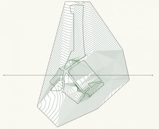
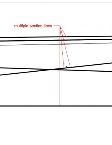
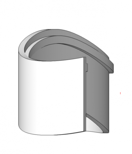
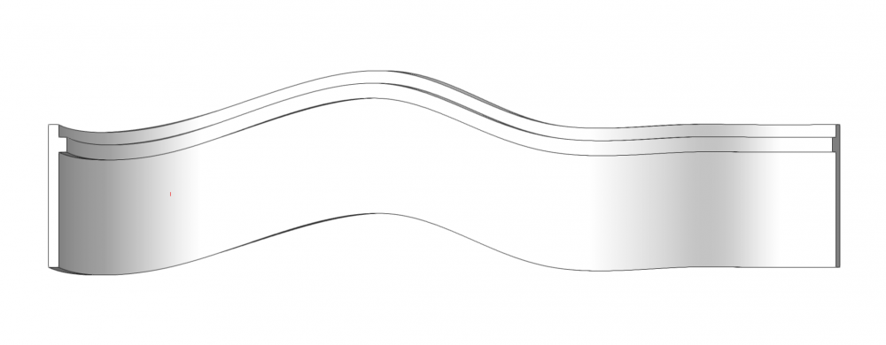
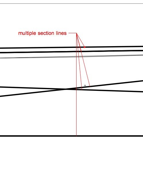
I've attached a file (VW2018) which contains a site model object, with a few site modifiers applying to it. In plan and OpenGL 3d view all is fine, but when I take a section through it (see the section viewport on the sheet layer) It's a complete mess, with multiple section lines all over the place.
The problems with this started out with it refusing to show fill in certain sections. Then, it refused to show fill in any sections. Now this.
What has gone wrong and how do I fix it?
-
8 hours ago, Matt Overton said:
Single section cut into multiple VP's to compress it,
yes... I do this all the time, and annotating them is a pain (although, sometimes I 'cheat' and put all the annotations in the annotation layer of one of the viewports but place them so they actually sit on top of the other viewports)
-
 1
1
-
-
5 hours ago, E|FA said:
The system would need to allow for separate VPs for each detail, but allow you to enter all of the VPs on a single sheet at the same time.
As I understand it, that's what is being suggested.
-
-
Has this removed the ability to quickly update callout notes from the database, and vice versa?
-
Regarding whether the site model should be sectioned as hollow or solid (I am talking about section viewports here rather than clip cube) - there are two scenarios where different behaviour is preferable:
(1) For a general site section, for example at early stages of a project, it is useful if the 'site' is shown as solid, with any buildings 'merged' into it. For these sections, what happens underground (foundations and so on) is not really important. These will tend to be the same drawings where components of walls etc are shown "merged".
(2) For more detailed construction stage drawings it is more useful to have the site model effectively "hollow", so that below-ground detail such as foundations *is* visible. The foundations will likely be shown sectioned but not "merged" - in other words the different components/materials will be visible. In this scenario, all I generally want for the site model is a single thick section line representing the ground surface. In theory this could be achieved with a "solid" site model but only if that solid has any below-ground construction subtracted from it - something that is not really feasible in practice.
For this reason, ideally the user should be able to choose which way the site model is sectioned, per viewport.
If it's not clear what the two types of drawings I'm talking about are, I can provide examples.
-
1
-
-
On 10/17/2019 at 5:24 PM, line-weight said:
While this thread is 'live' -
At least in VW2018 there are still issues with the site model being rendered hollow in *some* section viewports.
Is that a bug that was ever fixed?
See here
@bozho or @Tamsin Slatter are you able to comment on this?
-
On 10/8/2019 at 11:16 AM, Tamsin Slatter said:
Of course, in a section viewport, even one created with the clip cube, it's possible to display the section plane with graphics from a selected class, but I assume you want to show in a 3D view.
While this thread is 'live' -
At least in VW2018 there are still issues with the site model being rendered hollow in *some* section viewports.
Is that a bug that was ever fixed?
See here
-
On 10/31/2017 at 4:49 PM, zoomer said:
I assume the fill will not show when your section will cross any Pad Modifiers (?)
I am currently having the problems the OP describes.
It seems to be as @zoomer describes above, the fill disappears from those sections which cross site modifiers (in my case 'spoil piles').
Did any solutions to this arise?
-
1
-
-
2 hours ago, JMR said:
The VW help file is not very informative when it comes to curve degrees, here is a bit better explanation:
and
Thanks - I've maybe 60% understood the explanation in the Rhino link.
I don't think it explains what Vectorworks is doing though. For example I think I've understood that a higher degree is not necessarily related to a higher number of control points, which is what the VW Help explanation and/or edit behaviour implies.
I've also been looking at this GIF, where the degree setting is changed without affecting the control points, and where it can switch between the equivalent of 'interpolation' and 'control point' modes as @Benson Shaw was describing above (and is not possible in VW)
https://en.wikipedia.org/wiki/File:Spline01.gif

-
Yes, it could be useful. Although I don't find it too difficult to do at present, by placing the two text boxes next to each other and making sure justification etc is set up properly.
-
Yes, what started me off on this was when I got confused about why a NURBS curve had seemingly changed to control points without me asking it to. I think it was because I was fiddling with the degree number.
Are there situations where changing the degree is useful?
Like you my solution for now is to 'get over it' simply by never touching the setting, seeing as I don't understand what it does. But if VW has a setting like this, it ought to be properly explained in the documentation.
-
On 10/9/2019 at 9:48 PM, Benson Shaw said:
Yes, Doh! Good sleuthing @line-weight . Seldom used, so I have to relearn: 3d profile, orient and snap to end of path, Lock and Fix.
Coming back to this ... have realised, it's important to get the relationship of the profile and path correct in the Z direction when you create the EAP.
The reason for this is that going to 'edit profile' lets you accurately orient the profile relative to the path on the X/Y axes but there seems to be no indication in this view of where it is relative to the path in the Z direction.
It would be much more useful to have an 'edit' view where both the path and profile were visible (and editable) in 3d at the same time.
-
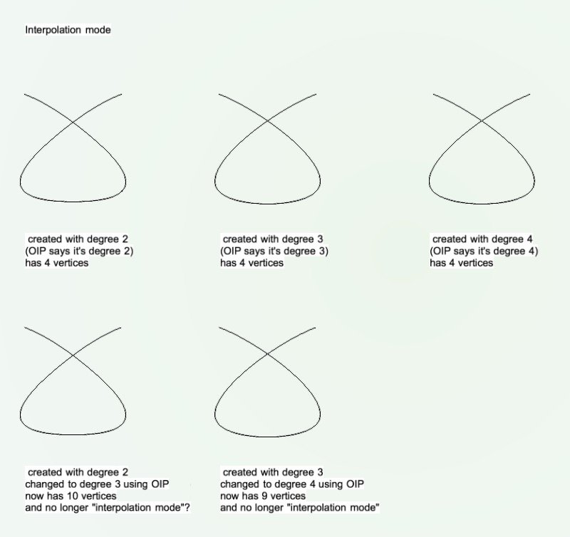
I'm pretty much completely baffled about what the 'degree' setting on NURBS curves actually does. Here's what teh VW help guide says:
QuoteThe curve degree affects the number of vertices created; the higher the degree value, the greater the number of vertices.
Here's what happens when I try various things:
(when I write "created with" I mean the number I put in the "curve degree" box of the NURBS tool settings)
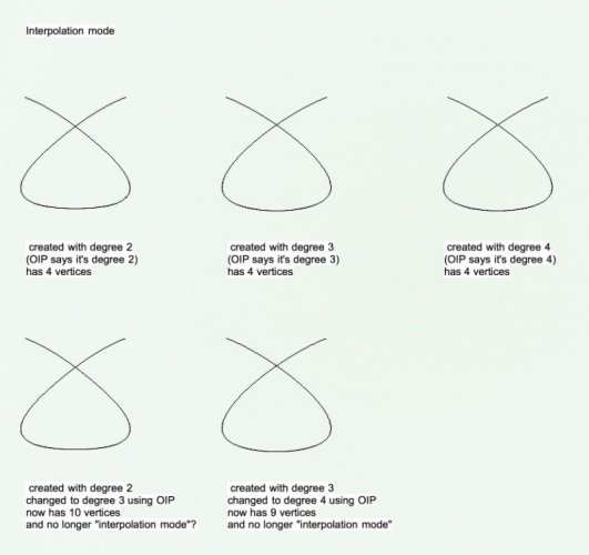
Each of those shapes is created by clicking on the same 4 points in the same sequence.
Here are some questions for starters:
"Interpolation mode"
1) Contrary to what VW help says, changing the 'degree' in the NURBS tool settings doesn't affect the number of vertices. It does seem to result in a slightly different shape though. So what does it do?
2) If I change the 'degree' number in the OIP, what exactly determines the number of vertices I end up with?
3) If I change the 'degree' number in the OIP, why does a line with degree 3 end up with *more* vertices than a line with degree 4?
4) Is it intended behaviour that changing the 'degree' number in the OIP flips an "interpolation mode" NURBS into being a "control point mode" NURBS?
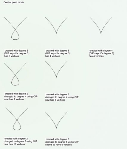
"Control point mode"
5) Why does the OIP tell me the NURBS has a different degree from the one I created it with?
6) Why does a created-as degree 3 or 4 NURBS have fewer vertices than a created-as degree 2 NURBS?
7) Why does on 'degree 4' NURBS have a different number of vertices compared to another 'degree 4' NURBS (and same applies to the two degree 5 NURBS)?
8 ) Why does one of the degree 5 NURBS have fewer vertices than one of the degree 4 NURBS?
Final question: is it user error, bugs in the software, or bad documentation that's causing the confusion here?
(I've attached the file below)
-
16 hours ago, Wes Gardner said:
I also noticed that your objects in the Untitled 23 file are about two hundred and ten MILLION units from the origin????
P.S. well spotted - this is also true in the working model I pulled it from. I don't think it's the cause of the problems but I have now fixed this in the original model to avoid other problems cropping up. Thanks.
-
Yes, strange use of the term 'linked'. As if intentionally to confuse.
When they say 'linked' what they really mean is something like "settings embedded in", right?
-
16 hours ago, Wes Gardner said:
@line-weight,Mine's not leaning over...I used a polygonal object and a NURBS curve as the path with Lock Profile Plane ON. I also noticed that your objects in the Untitled 23 file are about two hundred and ten MILLION units from the origin????
Wes
Did you use a 3d polygon, and what plane did you draw it on?
-
@Benson Shaw (or anyone else) - have you tried using the 2020 'hardscape' tool? Does it work - and/or go some way to addressing the issues discussed in this thread?
-
Well, it looks to me like the answer to this wishlist item is that there is an outright refusal to acknowledge the value of a dedicated forum moderator, and we're not going to get one. A very short-sighted decision in my opinion.


Site model object: section disaster
in Troubleshooting
Posted · Edited by line-weight
Here's what one of the site modifiers looks like when I select "show 3d".
Half of it sits on the surface of the model, and half of it seems to be at zero elevation. I don't understand how it's ended up like this. I don't know if it matters, but I suspect it does and is linked to the problems.
I don't know if there's any way of fixing it other than tracing over it with a new modifier, and then deleting it.The effect of this modifier is as it should be, when I look at the model in OpenGL. It's in the section viewport that something goes wrong.
*edit:
OK, so I think I have fixed it like this:
(1) Select the troublesome site modifier in top/plan view
(2) Convert to Group (it will now be a 2d polygon)
(3) In the polygon OIP change from "screen" to "layer" plane
(4) Adjust one of the vertices of the polygon slightly
(5) Select the polygon and use "create objects from shapes" command to make it back into a site modifier
(6) Now it seems to be fixed.
Step (4) seems to be sometimes necessary and sometimes not.
I think there may be some kind of bug involved in the "create objects from shapes" command.
In the future I will try and stick to making site modifiers directly from the site modifier tool I think.
Or maybe the bug comes when you edit an existing site modifier? Who knows. Doesn't look like anyone at VW is interested in finding out, anyway.