axhake
-
Posts
92 -
Joined
-
Last visited
Content Type
Profiles
Forums
Events
Articles
Marionette
Store
Everything posted by axhake
-
I’ve encountered similar problems with NURBS curves, (coincidently also trying to model a viaduct) selecting interpolated points mode I placed the NURBS curves through the alignment points I was given bu the client but the NURBS curves failed to pass through the points, it came close but not through. Similar problem as described above where the curve was faceted, adjusting the degree and weight made little difference. The way I managed to get something as close to acceptable as possible by creating the curve in another package and then importing in to Vectorworks. What may help was a Marionette script I found on the forum that Marissa created for someone wanting to divide a a curve into segments which does a similar thing, this may help
-
I have also found the same results using 2020, the curves are not displaying as the video.
-
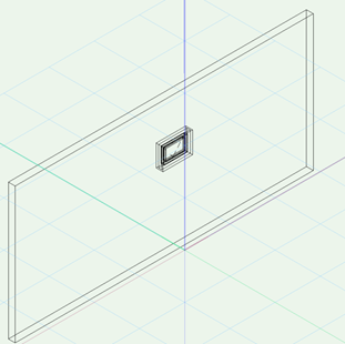
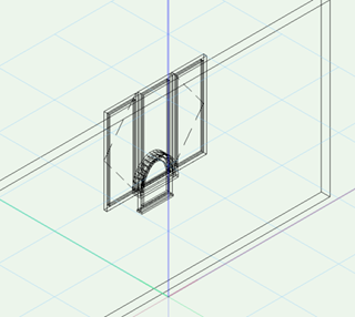
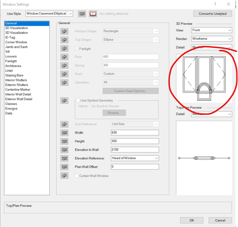
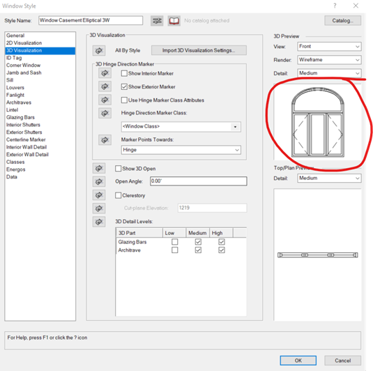
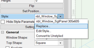
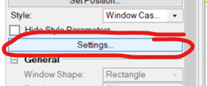
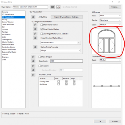
Just found this one relating to replacement of window styles: 1. Create a new document 2. Place a wall (unstyled) a couple of meters long 3. Switch to an isometric view in wireframe (just to make it easier to see) 4. Insert a window into the wall: Example used = Standard window metric library – “Window Bottom Hung Casement” 5. Select the windows and then from the OIP select: STYLE > REPLACE now replace the original placed windows with with a larger window (so you can see the problem): Example used = “Window Awning half circle 2W” from the “Custom Windows Metric” library. and then select OK The original window style is still visible (but displayed as a triple panel window) alongside the new replaced style. 6. Select the window (they both are selected as if one) and in the OIP select settings The preview shows both the original placed window style and the replaced window style 7. Selecting the window again and then in the OIP select: STYLE > EDIT STYLE The replaced style is shown correctly ¯\_(ツ)_/ ¯ Vectorworks 2020 Windows 10


-
Draw 3D polygon line through x,y,z points from text file
axhake replied to axhake's topic in Marionette
Oops, sorry forgot to update signature. I'm on 2019 now (... just updated my signature) it should now show that correctly. Many thanks for providing a solution to my problem, I'll have a look at your network and see how it works. I assume the "tuple" node is a custom node you created? -
Draw 3D polygon line through x,y,z points from text file
axhake replied to axhake's topic in Marionette
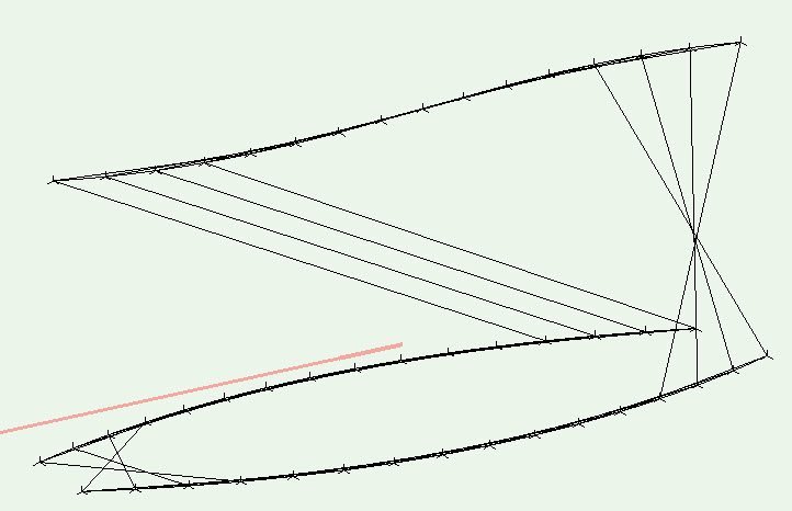
Did try the extract line tool but the DTM when ungrouped only gives you a line between two points due to the triangulation and not a continuous line bwtween all of the points. Attached is what I am trying to end up with, a continuous 3D line bwtween all of the points. I was wondering if Marionette had the capability of reading a text file with x,y,z coordinates in and passing this to the relevent node 10 metre points xyz.vwx -
Draw 3D polygon line through x,y,z points from text file
axhake replied to axhake's topic in Marionette
Thanks Hans-Olav for the quick reply, In this instance the design line represents an edge of a walkway/ramp (not a surface) that we have to work up to and use as our design line to work from. I did try creating a DTM from the points but the amount of work needed to get back to a single 3D line prompted me to see if there was a quicker way to do this. All that is needed is a 3D line that passing through the points -
I’m trying to input a series of point that were delivered in x,y,z format in a text file that define a design line to work from. I’m able to load these points into Vectorworks using the “Import Survey File” as 3D Locus but haven't found a way to draw a 3D polygon line through these points other than doing it manually which is very time consuming when there are hundreds of points. At the moment I have to take the text file and turn it into an AutoCAD script by adding the command “3Dpoly” as the first line of the file and then run the script within AutoCAD where is creates the design line, after this I have to import into Vectorworks. Where this does work it is time consuming and does require an additional CAD package to do this. I have been looking for a way to do the same within Vectorworks but so far have been unsuccessful and though Marionette might have a way to do this but my knowledge of Marionette is very limited at the moment and could not find a way to read the values from the text file,;any assistance with this would be much appreciated. Example x,y,z file attached. 10 metre points xyz.txt
-
Had a little play with your file; I exported it from ProgeCAD (didnt have AutoCAD) as a STEP file which came into Vectorworks displaying all surfaces. From there it was a quick extrude and copy for the treads, copies the stringer frames to the side and traced over, extruded and copied back into place, quick sutraction of the posts at the bottom and delete all old surfaces. just under 10 mins while I was waiting for AECOsimto finish rendering a plot. Stair - STEP converted.vwx
-
Teaser Tuesday - Class and Layer Filters - Vectorworks 2019
axhake replied to PVA - Admin's topic in News You Need
I did try and join the on-line QnA last week but was working late and the company I am working with at the moment has Facebook on it blocked list, so was unable to join. Q. Nothing was mentioned in the video or text in your original post to say if “Boolean” search could be used in any of the search fields. Having the ability to use operators (or modifiers) i.e., AND, NOT and OR and also quotes “”, would just about round off the search capabilities. The Boolean Search could be incorporated as an option at the end of each line to include another search line and provide this capability graphically. Ps. "Boolean" search capabilities would also allow you to include (None and Dimension) within your search. Q. Also is there a limit to the number of “TAGs” that can be associated to a layer, class... etc? -
I have been using the "Drilled Footing" tool to place piles on a project I am working on at the moment. The project requires straight piles (no bell end to them) so I have been setting the "Bell width" and "Bell height" to 0. All displays correctly but when I checked the length and toe level they are not correct. Example of 600mm pile with a toe level of -5000. 1. Create a new file 2. Select: Building Shell> Drilled Footing 3. Enter the following: x = 0 y = 0 z = 0 Rotation = 0 Diameter = 600 Bell width = 0 Bell height = 0 Top datum = 0 Bearing datum = -5000 Now check the top and bottom levels of the pile (drilled footing): Top level = 0 Bottom level = -5300 Measured length = 5300 The length should be 5000 but it has increased by 300 However if I set: Bell width = 600 (same diameter as the rest of the pile (drilled footing)) and Bell height = 0 the pile is now drawn and measures correctly. Is this the only way to draw a pile without the bell end; should entering a bell height and width of 0 give the correct length? It would useful if the ("z" /Top Datum) could be tied into the stories.
-
It's nothing new, other software packages like Microstation has had this facility since v8, AutoCAD Layer filter is much better as you can save filters for future use. I Myself and others I have seen in many webinars and demos spend a lot of time searching for a specific class (or layer) to manipulate (turn on/off or use for the placement of graphical elements) which gets frustrating as the days goes on; where having a filter capability would speed up there workflow and assist in choosing the correct class/layer to place graphical information upon thus improving efficiency. The Uniclass 2015 tables located on the NBS site has a filter for just this reason as there are lots of tables and many codes to select from, searching manually would make it unusable, with the filter the user is presented with all codes that match there filter e.g., "column" would list only codes that contain the word "column", if you were to expand on this to "column steel" the list is then shortened to find only codes containing the words "column" and "steel". Unfortunately Uniclass codes are only likely to grow in number (as with other codes), having the capability to filter is essential.
-
It would be relay useful to have the capability to filter for a class name when creating a new class by importing from a class library file. At present when importing from a class library file you have to scroll through many lines of classes to try and find a class name the best fits your needs especially when using Uniclass which can contain many lines of classes. It would be easer and more efficient to be able to enter part of a word to match. e.g, filtering by "stair" would filter out only classes containing stair within the class names thus shortening the list to chose from and making it easier for the user to select the correct class. It would also be useful to be able to filter the classes within the navigation palette to be able to locate classes containing a search pattern a lot quicker than manually having to search through long lists of classes as you have to do at present.
-
Still no reply from VW UK, I have just submitted this as a BUG.
-
It's been with UK Vectorworks support for a couple of weeks now, I'm awaiting a reply, will update this post when I receive a reply. Alan
-
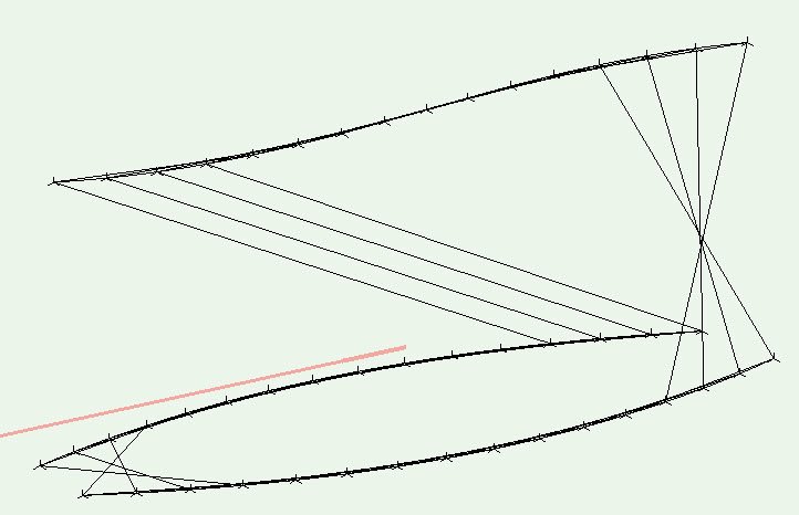
Not sure if this will be of any use to anyone but I have been drawing up a viaduct structure where a control line was provided from another design team using Microstation. The control line is from a railway lower rail level so any calculations, setting out etc need to be accurate. The design string is made up of vertical and horizontal curves with two transitions. After spending several days trying to create the viaduct which the building surrounds to form a station building I found several problems with the way Vectorworks manages polylines/qubic spline curves. To demonstrate the problem a simple model was created in Vectorworks and as a comparison to see how other CAD software manages spline curves I also created the same model in (Microstation, ProgeCAD, ArchiCAD) to compare the results which can be seen in the attached PDF in the native application and also when exchanged/referenced into the other CAD software. All but Vectorworks managed to create spline curves that pass through the control points, Vectorworks came close but not through the points which explains the problems I was having. making collaboration with others a problem. Vectorworks_Notes.pdf
-
Hi Jim, I am having a similar problem, have raised this with CU this morning but as yet not resolved. Story so far: 1. Downloaded the "Vectorworks2015-SeriesB-win" installer. 2. Started install and entered the serial number as shown under "My Licenses" on the VSS portal. 3. Install went through without any problems. 4. re-booted 5. plugged USB dongle in (HASP HL) 6. Started Vectorworks 7. Message diaplayed "A Vectorworks dongle could not be found. Make sure that the dongle is connected and that all required drivers have been installed. Vectorworks will now quit" ... and it did! 8. removed dongle and updated dongle drivers as per readme file. 9. re-booted and tried again, same error message. 10. compaired version of driver downloaded to the one HASP HL - both were the same version. 11. Checked the dongle ID, this matched the SN. (dongle lights up as normal). After uninstalling and re-installing several times I tried removing the registration folders from the registry and started VW2015 once more, it asked for a SN, I entered the same SN that I used when installing VW2015 but it rejected it this time saying "The entered serial number is invalid. Please carefully re-enter the number", leading me to think once again that this was a problem with the SN. I had another thought and entered one of the beta SN's in that was sent to me some time ago, it accepted this SN but would not proceed as this had expired, once again leading me to think the problem is with the SN and not the dongle. Will email you the installer log file for reference. Windows 7 x64 Dell M4400, 8GBram, 512Graphics
-
I am also having similar problems with dxf file and geo-coordinates graphics. Push Pull stopped working within these files and Fit to Objects not working as should. Here in the UK I am involved in manage many large civil project, all requiring informtion to be drawn and shared in coordinated space, this seems to be a big problem with VW, which means a big problem trying to exchange coordinated information with others, a problem I have not encountered with Microstation, AutoCAD or GDS/MicroGDS (only with the users and not the software). I agree also that DWG/DXF are industry standards in exchanging information, having a work around using 'dummy' file is not a cost effective way of working. these two areas need to be addressed as a prioity. Alan