


Josh NZ
-
Posts
406 -
Joined
-
Last visited
Content Type
Profiles
Forums
Events
Articles
Marionette
Store
Everything posted by Josh NZ
-
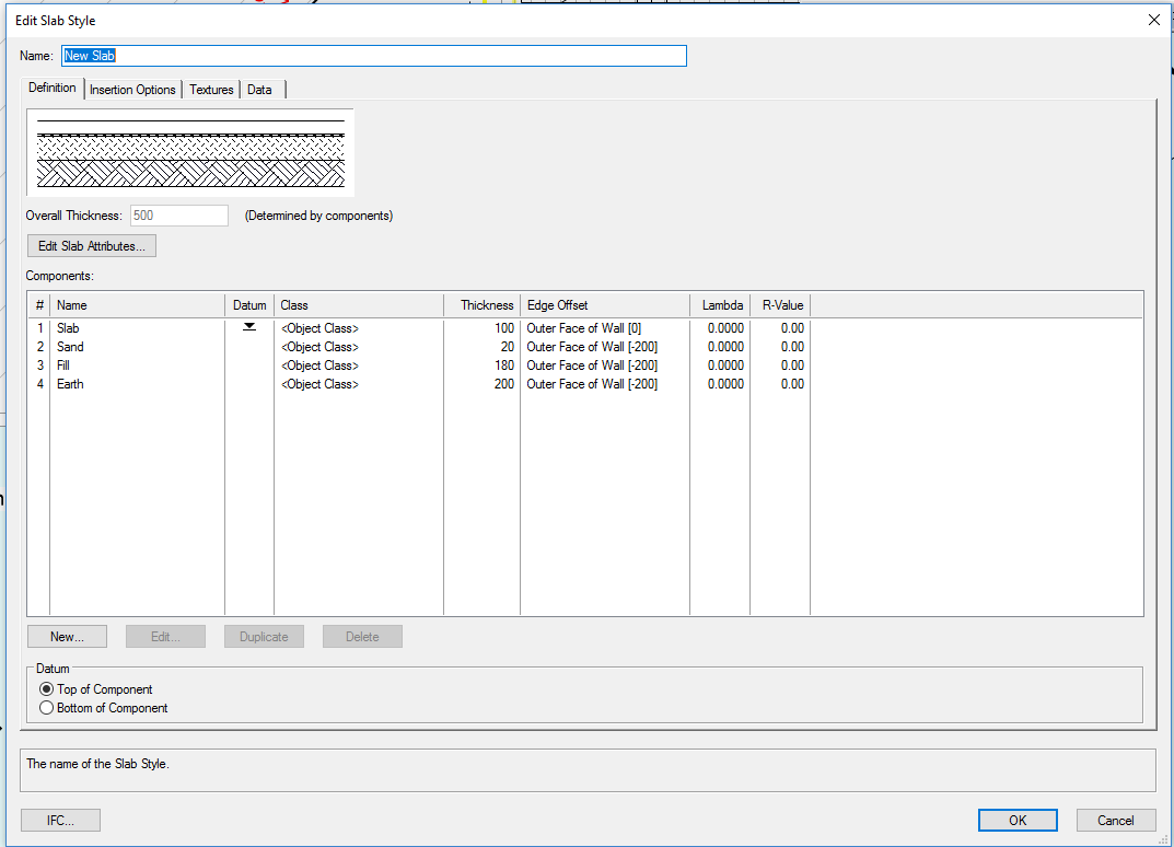
I have set up a slab style as shown in the below image. As you can see in the offsets have set the lower 3 to have a -200 offset so that I can draw conc blocks around perimeter. The style has worked fine for most applications. Have a growing need to the -200 offset to 3/4 sides with no offset to 1/4 side (Basically where the slab is adjacent an existing structure). Is there a trick to get the object to show offsets to selected sides only or is this a case of having to use a work around. Thank in advance.
-
 I am curious on how other offices set up their cad files with respect to multistory dwellings. At the moment for a single storey structure we have a Design Layer for each of the Floor, Walls and Roof heights of a dwelling. For say a two storey structure we repeat the same three layers. The class list is fairly simple, Walls Ext, Walls Int, Roof, Floor etc. In particular my query is to do with how people show two similar objects in two different ways in one plan. An example being the roofs on a First floor plan. The ground floor roof is shown solid as it is below the plan. The first floor roof is shown dashed as it is above. One approach is two have a class for every roof and layer, eg Ground Roof, First roof etc. The other way which I use is to have a DL VP which shows just the first roof dashed. That way can keep the simple class list and still use a class override for most objects. Hope all that makes sense.
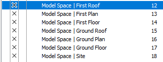
-
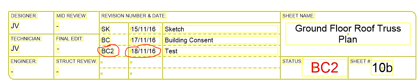
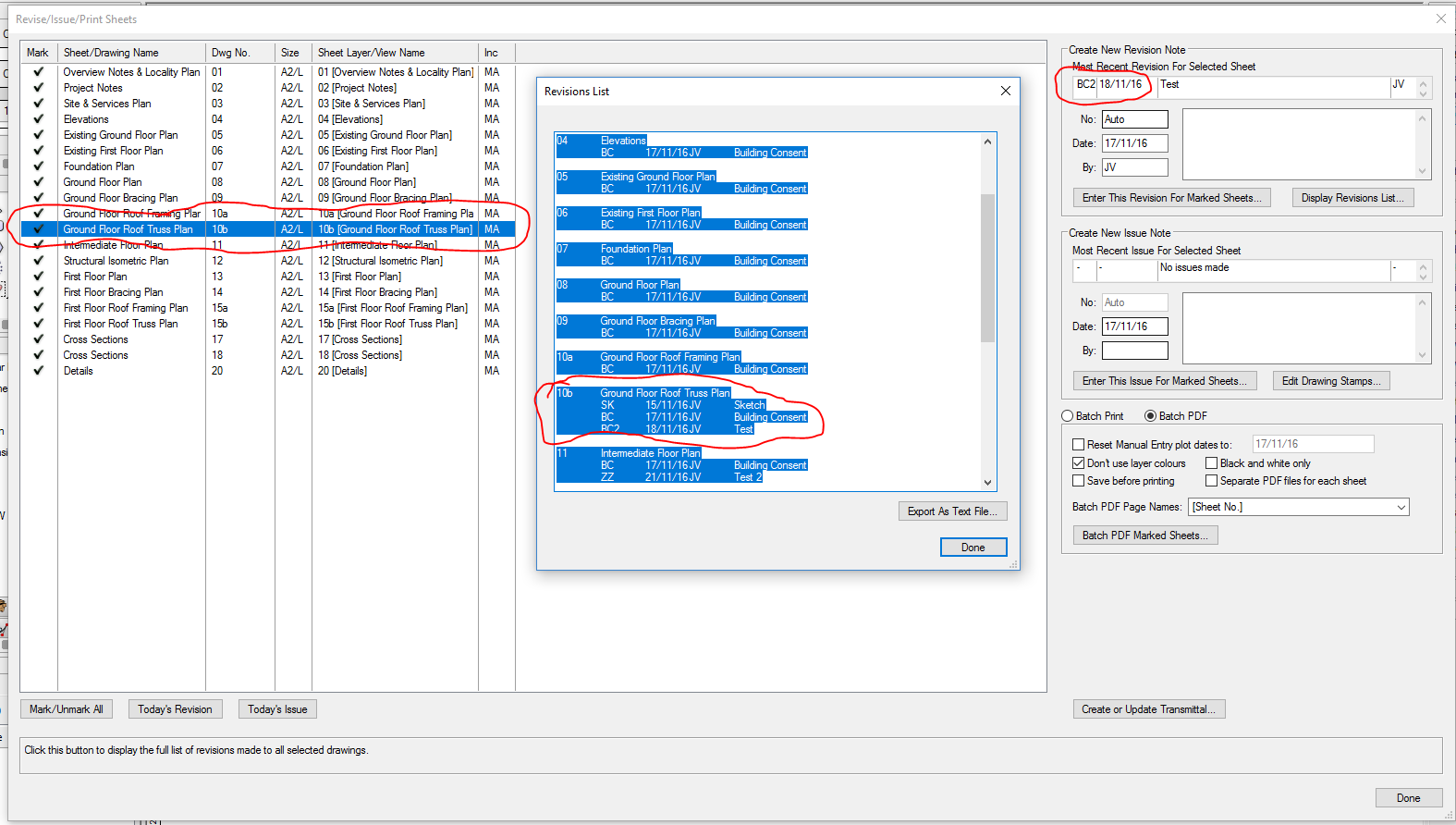
In addition I have tried to enter a third revision to see if that will kick it in to action. This has now listed the incorrect date in the transmittal and removed the previous entry.
-
The data is in the form of a spreadsheet not database so not able to recalculate. When creating I have ticked the option to create new rather than update existing. Have restarted VW and also run the reset all plugins command.
-
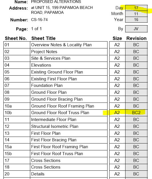
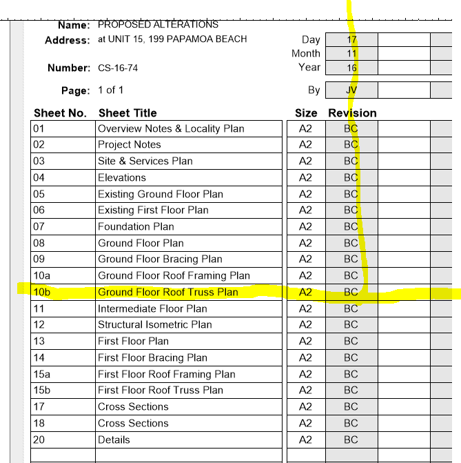
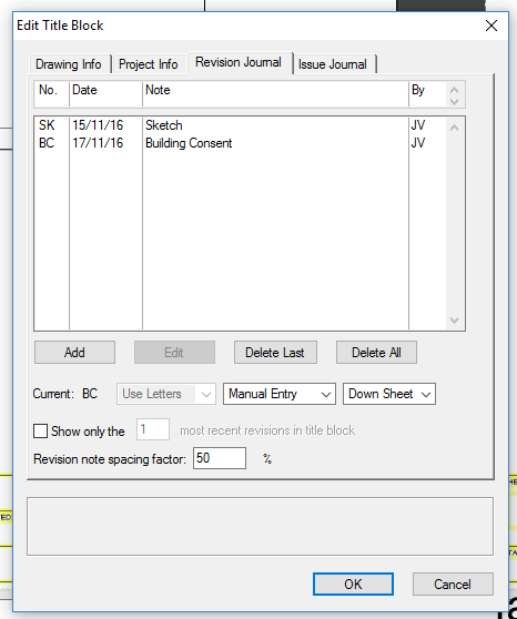
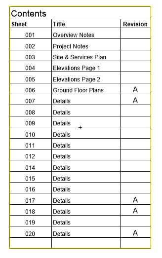
I have several VAA titleblocks. All have one revision entries. Have used the VAA Revise Issue Print command to create a Document Transmittal as shown below. Not all revisions are showing up in the Transmittal. Any ideas why?
-
Thanks for that BG. I have viewed that video, while you can add more info there is no option to show that added info on the ID without sacrificing another piece of info. The info can all be displayed in a worksheet which is handy. On plans thou often need to show more info on a window ID, such as the Number, type, size and lintel.
-
The clip cube can also be used to create a sectional viewport. Click the face of the cube so shows red, right click, then the option is down the bottom. Have started using this quite a bit. Hope that helps.
-
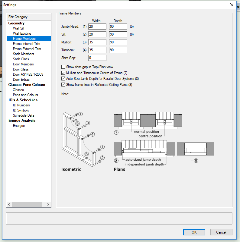
Definitely agree, windoor is a great tool, below is just a couple of examples of the areas you can adjust.

-
Render of Viewport Changes when Size/Scale altered
Josh NZ replied to Josh NZ's topic in General Discussion
Hi Jim, yes the above still showed after clicking update. On the second image I ticked then unticked "display planer objects", this made the same change to the appearance. I then changed to openGL and could see the image again. -
Im using VW2017 now and have already changed this setting 5 times today on one file. Will this be fixed in a service pack or next version?
-
Render of Viewport Changes when Size/Scale altered
Josh NZ replied to Josh NZ's topic in General Discussion
Also if I change the Foreground render from hidden line to none the whole VP shows as blank. Have set Background render to Final Quality Renderworks and still shows as blank. -
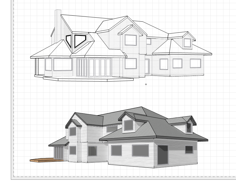
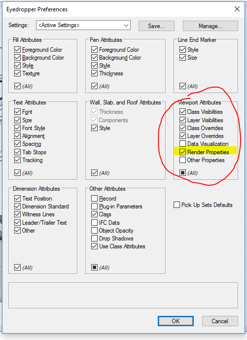
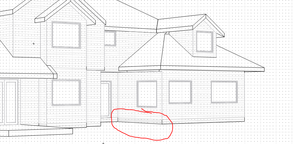
I have two viewports both had the same render settings (bottom image). I adjusted the scale of the upper image and now looks as shown. Have tried to use the eyedropper tool and have ticked the options shown below, this has no effect on the upper VP. Any ideas?
-
I am now using VW2017, still experiencing the same issue. Is this going to be fixed in an update or next version?
-
With the windoor tool you can set different ID symbols depending on what schedule they are, eg door, window etc. Im thinking my query isn't possible but will ask anyway. First query: Is there any way to add more than just a second field for the ID, eg in the image I have selected Unit width x unit height I would also like to have a field for head height and possibly another one such as User Additional Info so that I can enter a lintel size. Second query: The ID shown in the image is great for a floor plan at 1:50 however in the elevations which are at 1:100 the text is too small and has the second line of information which isn't required. Have tried to edit the ID symbol in the resource browser and make the second line of text have a different class, however this had no effect and still reverted to the visibility and attributes of the none class.

-
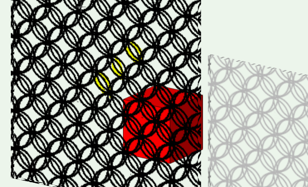
Thanks for the help guys. I am part way there using a texture. The attached image used a pix-elated image so will retry. In the meantime is there a way to make the two faces of the texture link, eg in the attached image I have highlighted in yellow the gaps. Left face has the texture, right face has the texture but there is a gap in the middle. Hope that makes sense.
-
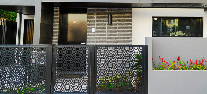
I am about to replicate the below image and wondering what the best approach would be. I know I can use a texture and set the transparency mask to match the image. Might not get the crisp edges. Can create using an extrusion but would mean slightly longer process to alter design if required. Could maybe use Marionette? Which I don't even know where to start. Any ideas/tips?
-
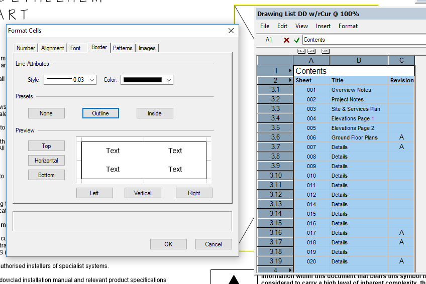
Thanks for that Michael, did the above and achieved what i'm after. For anyone else it would probably also pay to note that the line style needs to be set to none in the Attributes palette. I left mine as solid black and every cell still showed up with a border. It was only once I changed the line type to none that only the outline showed up.
-
I have a worksheet which im wanting to show with an outline to the perimeter only. Have gone into the format cells dialog and unticked "inside". Then ticked "outside". In the review it appears how I want it to. As soon as I exit thou every cell has a border. What am I missing?
-
BG, i did find for a second that it hadnt worked on a a couple of walls, but it turned out I was setting the Z origin for the right face texture not the left face. I think it also made a difference if one was set by component not by object. In VW2016 you can also use the attribute mapping tool. Just a bit of a lengthy process to go through each wall/object and adjust. Also the nudge button works with hatches but if you try it with textures it will move the whole wall.
-
Funnily enough whilst scrolling down to read your reply I could see only the bottom slither of my attached image. Noticed the "use world Z for origin". Ticked this for all walls and it seems to have had the desired effect. Don't know how I have kept missing this, maybe as its separate to the map type and offset V function.
-
The following is a problem that has plagued my files for awhile and im afraid will be a quite a noob problem. All the walls in my projects are classed Walls External or Walls Internal. Each class has a render setting to the right and left of wall. In the attached image I have selected weatherboards as the left render style. Looks fine apart from at some junctions the textures don't line up. Im guessing this is because somehow the texture is linked to the boundaries of the object as opposed to more of a world based setting (similar to ho hatches work). In the Render settings I have chosen auto-align plane for both walls however the two textures still don't line up. I know I can manually adjust the vertical offset but hoping to find away to have all walls set up when drawing so that regardless of texture chosen they will all line up unless specified otherwise. Can anyone point out where I am going wrong? Thanks in advance.

-
Has there been any development on this? I left the original from above to publish for about 45 minutes and still didn't finish. I am reluctant to start working on VW2017 if unable to publish. It turns out exporting back to VW2106 causes "Spaces" to loose their info.
-
I have around 10 vectorworks files for 10 different small unit types. All were created from he same base file and all are around the same size. For some reason when saving one of them it takes around 1 minute compared to 5-10 seconds for the rest. Whilst the save is happening the progress bar in the bottom right reads "Waiting for previous file operation to complete". Does anybody have any ideas what causes this and how it can be fixed?
-
Im trying to replicate and entry door similar to the below image using the windoor tool. Can only find a few options thou, flush, paneled, glazed. Not sure if this is possible without exploding or creating other modelling elements. Any tips?
-
As a workaround I exported to VW2016 and published from there, took around 5 minutes.
