PeterT
-
Posts
593 -
Joined
-
Last visited
Content Type
Profiles
Forums
Events
Articles
Marionette
Store
Everything posted by PeterT
-
shortcut for rotating plan view
PeterT replied to Cadplan Architecture's topic in General Discussion
Also, Command 5 (Top/Plan) will restore the view to 0° from whatever angle you are displaying. -
I am surprised to see the original Bridge Line Tool was not fixed in the 2017 SP4 update. I am sure this is an easy fix for the engineers, but it took me several days to write my own Bridge Line Tool in Vectorscript. I guess I must be the only one using this tool, as it seems of no importance to anyone else. Besides, I am sure the there were much more important things to fix. I do not care about Bug VB-138438 anymore. I will just use my own tool. As far as I am concerned, you can just remove the broken Bridge Line Tool from the Application. Thanks to everyone who helped me get my own Bridge tool working, apparently it was not wasted time.
-
Hi, I have an event enabled plug-in that is my sheet number. I double click it and a dialog opens up to populate all my sheet numbers. I have always had the sheet number locked so that when I double click it it does not accidentally move. Several versions ago, It would open the dialog even though it was locked, but more recently, it no longer opens, and gives me the locked object message. Now I have to unlock the sheet number, double click it to update the sheet numbers then close the dialog and re-lock the sheet number. This sort of removes the protection I had of not accidentally moving the sheet number when editing. The question I have is whether there is anyway that I can write code into the plug-in such that when I double click the locked plugin it will unlock to open the dialog, then re-lock when I close the dialog. I tried adding the UnLckObjs and LckObjs calls in the script but it did not work. Is there any way to do this?
-
OK, I had them both at 600 dpi. I do not understand how you can have a high resolution image at 72 dpi and only 26 x 2o pixels. I will reduce them to 72, but that does not sound high resolution to me. Peter
-
Raymond, I do not know how you got them to import. I get the same message every time. I even renamed them the same as you did. Peter

-
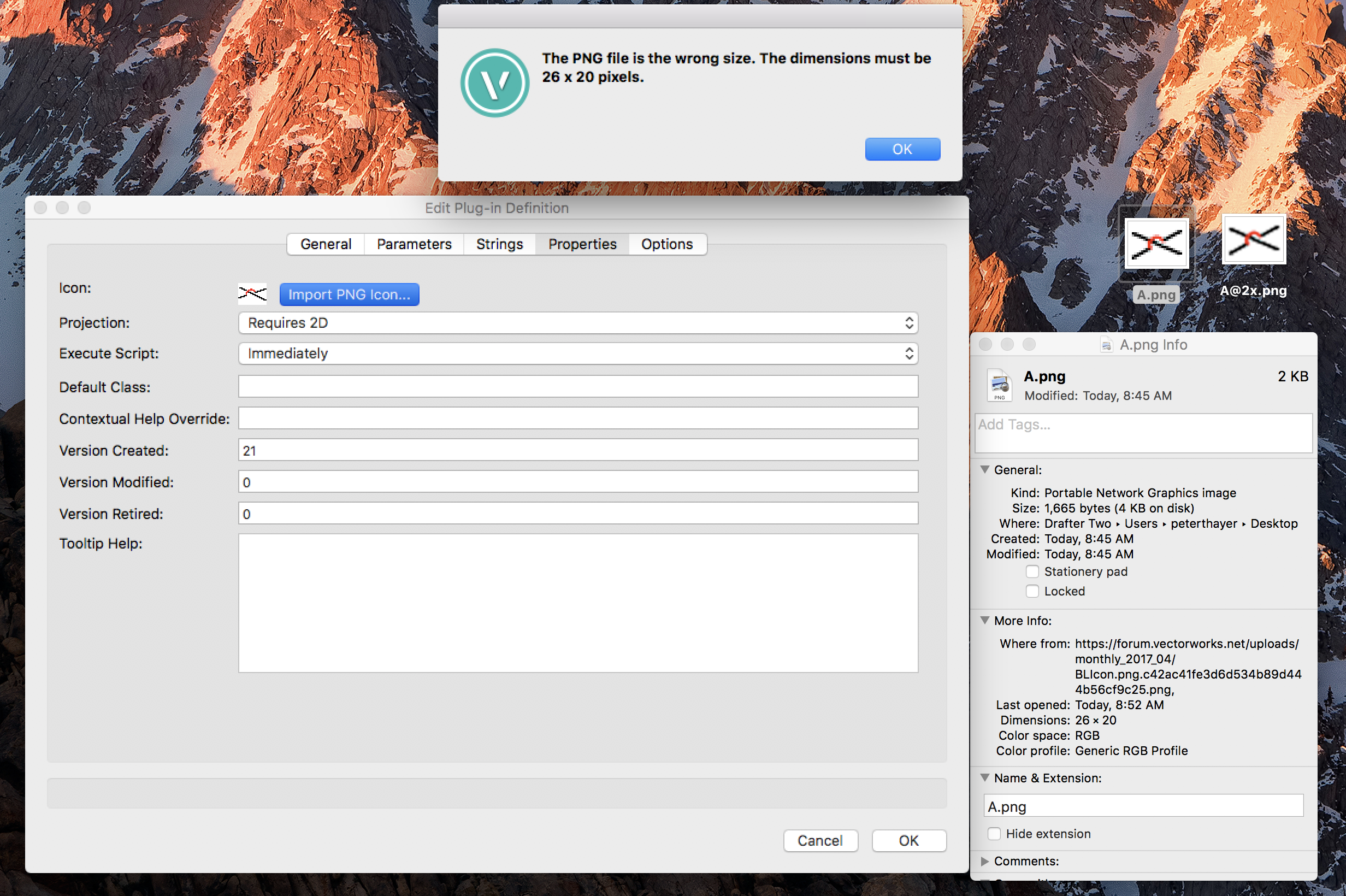
O.K, I am about to give up on this. I have a 26x20 pixel PNG Icon named BLIcon.png, and a 52x40 pixel PNG icon named BLIcon@2x.png. I Open the BLIcon.png file in Preview, Photoshop, or Graphic Converter and they all tell me it is a 26x20 PNG file. In VectorScript I hit the Import PNG Icon... button, select the BLIcon.png file, and get the message that "The PNG file is the wrong size. The dimensions must be 26x20 pixels". I have verified 20 times that it is a 26x20 PNG file yet VectorScript sees it as something else. I cannot spend my whole day trying to import a stupid ICON. I guess I will just have two accept the low res icon since VS will not take the file that it asks for. Here are the two Icons, as I do not know where to go from here.


-
Josh, Since Vectorworks and the Plug-ins reside on seven different workstations in my office, are you suggesting I put two image files on each of seven workstations? Or can a workstation copy of Vectorworks pull the icons from our server? I typically Paste the icon in on my workstation, how will the other workstations find it? Is there anything about this on the Developer Page? I have not seen it. Peter
-
Josh, As you Paste the image into the Properties dialog, what directory do I put the High res image into? Where does Vectorworks store the image that was pasted in? Is that where I need to put the high res image? Thanks, Peter
-
On another note, when pasting in a 26x20 pixel tool Icon in the Edit Definition Properties tab, how do you get a high resolution Icon. I made my Icon in Graphic Converter, but when I pasted it in, I got some sort of a message saying that it would be a low resolution Icon if I do not make a high-resolution counterpart, or something like that. What is the technique to get a high resolution tool Icon?
-
Pat, It appears that if you use __NNA_DO_NOT_CHANGE as your Parameter alternate name, that makes it permanently hidden. You do not the seem to be able to make it visible again with SetParameterVisibility(h, 'parameter name', TRUE); Is that correct? Peter
-
All, I have gone one better than your suggestions. I have set my Angle and Sweep to 179.999 and this also fixes the flipping problem. I realize that a 180 and a -180 sweep get you to the same place but the direction (Positive or Negative) should draw the sweep one way or the other. This must be a 2017 bug with ArcByCenter as it works fine in 2016 at 180.
-
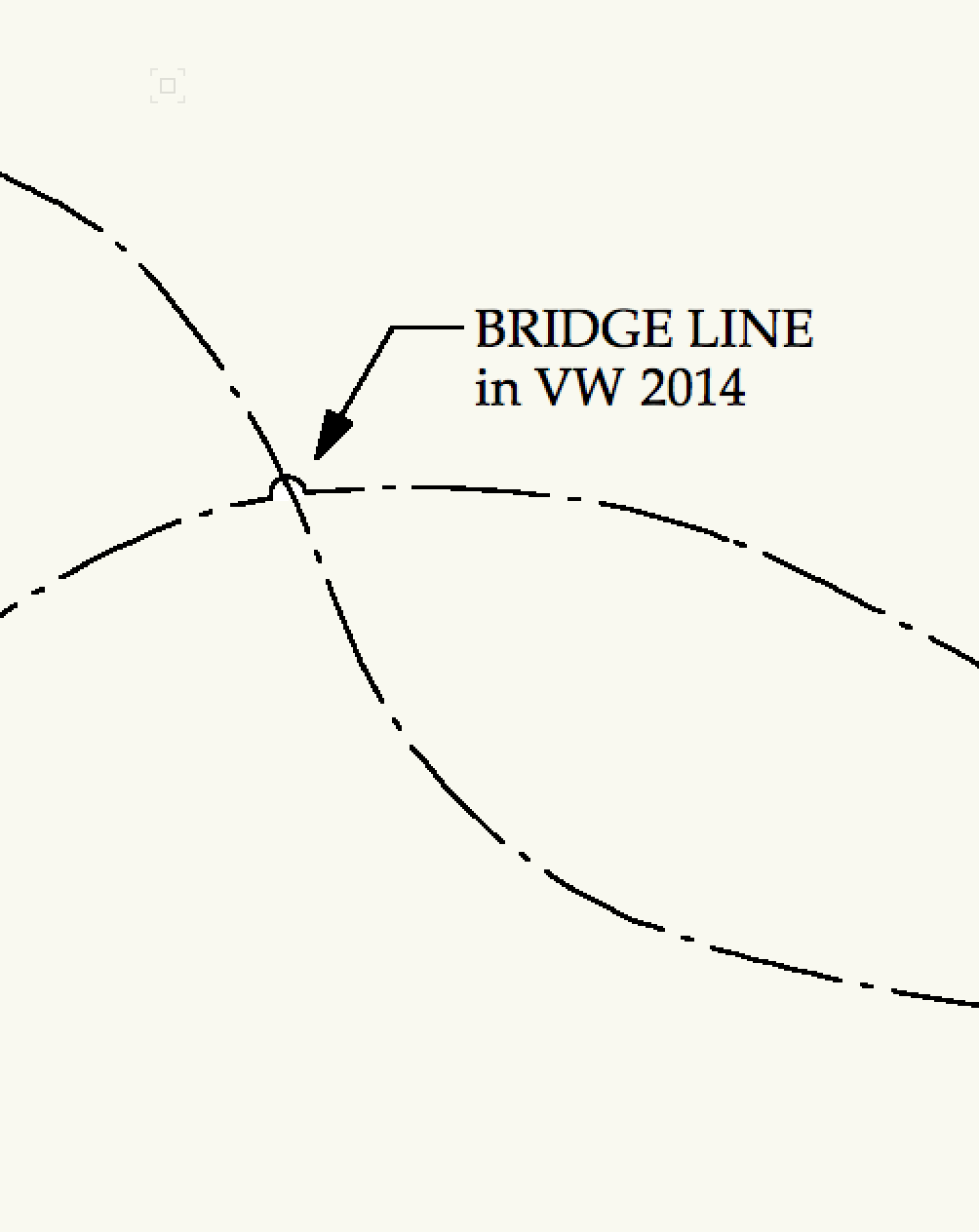
Josh, Thanks for the tips. Raymond also gave me some of the same information and cleaned up my script. Already did this in the second posting of my code. Not sure what you are asking here. Just like the Nemetschek Bridge Line tool, I only want to see the Cover Weight field if I check the Set Cover Weight check box. I only want to be able to adjust the cover weight of the straight line. There is no cover weight of the Arc. The Arc line weight is just set by the document default line weight. The reason I did this originally was that if I drew the shorter Cover weight line first it was putting the object handles at the ends of the shorter line not at the end points of the arc. So I first drew a full-length line to establish the full-length, then deleted it and drew the adjusted shorter length. Not sure why this does not happen with Raymond's corrections. But if you comment out the drawing of the first line in my original code, you will see that when the object is drawn, the handles are inset from the ends of the arc. Not so true. If you draw an Arc of 9 mils and a cover weight of 17 (or more) mils, the ends of the cover weight line will stick out further than the Arc, and you will end up with white gaps in you wire on each side of the Bridge line. This object is not for just drawing in space, it is for drawing a bridge over crossing wires on an electrical plan. Wires on an electrical plan are rarely straight, so to cover the curved wire lines you need to bump up the thickness of the cover so that it hides the curving line that it is covering. I really shouldn't even have to be writing this script, but the inherent Bridge Line tool has cover behind the Arc which it should not. If you want to see what the Bridge line tool should draw, draw one in VW 2014. That is the last version that drew the Bridge line correctly. I am still waiting for the powers that be to fix the tool, so I decide to write my own tool. Maybe most people who draw electrical plans just cross their wires and do not use the tool, but really that is not correct. Also, it is odd that in version 2016, the original tool that I wrote works perfectly. It only has the arc flipping sides in version 2017.
-
Pat or Raymond, One more question. Why is it that when you first place the object, or click on the tool preferences button and the "Object Properties" box comes up, the Cover Weight setting is visible, even though the Set Cover Weight checkbox is not checked. It works properly in the OIP but not on the Object Properties dialog. Shouldn't they be the same? O.K., I just looked at the Nemetschek Bridge Line tool and it is the same thing with the Object Properties dialog. I guess the Object Properties dialog ignores the SetParameterVisibility calls and displays all parameters regardless of their visibility settings. Peter
-
Raymond, Thanks for the cleanup. Not sure why I had all the trigonometry in there, but I was having trouble getting the handles at the ends of the arc rather than at the ends of the shorter cover weight line. I will have to examine your fix as shorter is definitely better. And of course I forgot about Pushing and Popping the attributes, which I have used many times before. I guess I was just focusing on getting the Arc to draw properly. Thanks, Peter
-
Pat, If you comment out the RotatePoint(0,0,45); you will see that the line draws at 45° to the arc, so I have to rotate the line to be in the same orientation as the arc. ( maybe there is a better way to draw the line so I do not have to rotate it after it is drawn, but I could not find it). And RotatePoint must assume degrees because it rotates the line 45 degrees. As for the "swp :=180; and the IF flip THEN swp := -180; that is just changing the sweep direction of the arc from positive to negative, which flips the arc to the opposite side of the line when you check the "Flip" checkbox on the OIP (Just like the built-in Bridge Line tool). ArcByCenter just draws the arc. It starts in the center "bridgeline/2,0" (half the linelength), and the radius is "bridgeline/2" (half the linelength again) and the angle is 180 and the sweep(swp) is a variable ( either 180 or -180 depending on the Flip checkbox). And if the commented out lines are confusing, here is a cleaned up version without comments: PROCEDURE BridgeLineNew; VAR bridgelength : REAL; setcoverweight : BOOLEAN; coverweight : INTEGER; flip : BOOLEAN; cursize : INTEGER; R : LONGINT; G : LONGINT; B : LONGINT; P : LONGINT; result : BOOLEAN; objn : STRING; objh : HANDLE; objrech : HANDLE; wallh : HANDLE; adj : REAL; swp : REAL; obj : HANDLE; BEGIN result := GetCustomObjectInfo(objn,objh,objrech,wallh); IF result THEN BEGIN bridgelength := PLINELENGTH; setcoverweight := PSET_COVER_WEIGHT; coverweight := PCOVER_WEIGHT; flip := PFLIP; IF NOT setcoverweight THEN SetParameterVisibility(objh,'Cover Weight', FALSE); SetParameterVisibility(objh, 'LineLength', FALSE); cursize:= FPenSize; FPenFore(R, G, B); P := FPenPatN; PenSize(coverweight); PenFore(65535, 65535, 65535); PenPat(2); Line((bridgelength)*sin(Deg2Rad(45)),(bridgelength)*sin(Deg2Rad(45))); obj := LNewObj; DelObject(obj); adj := (coverweight*.0254); MoveTo(adj/2,adj/2); Line((bridgelength)*sin(Deg2Rad(45))-adj,(bridgelength)*sin(Deg2Rad(45))-adj); RotatePoint(0,0,-45); PenSize(cursize); PenFore(R, G, B); PenPat(P); swp := 180; IF flip THEN swp := -180; ArcByCenter(bridgelength/2,0,bridgelength/2,180,swp); END; END; Run (BridgeLineNew);
-
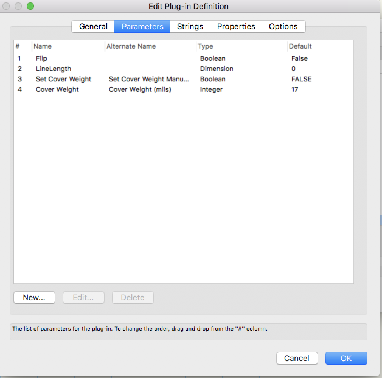
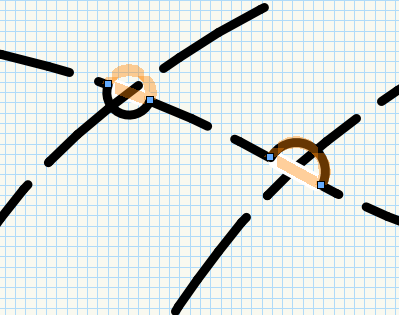
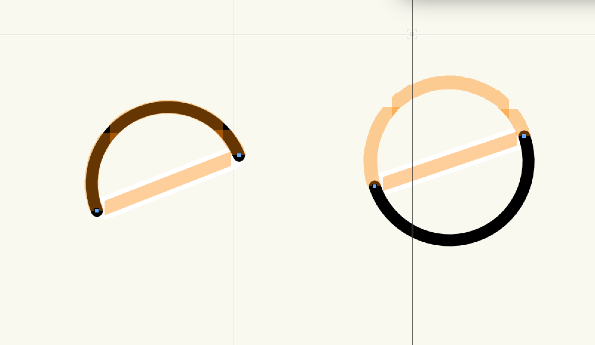
Hi Pat, Thanks for having a look at this. Here are the Parameters: Most of the time when originally drawn, the arc does not Flip. Also, if down at 90° or 180° it will not flip. But when you draw it on an angle and resize it, it randomly flips. You sometimes have to resize it several times to different lengths and eventually it will flip, but not in VW 2016, only in VW 2017. As for which way to draw the arc, the Flip parameter checkbox flips the arc just fine. But what I am saying is it sometimes randomly flips the drawn arc even though the ghosted arc that you can select does not flip. This happens without checking the Flip checkbox in the OIP. This random flip usually happens when adjusting very small arc lengths, like just over a 9 mil wire on an electrical plan at 1/4" scale Here is a test file, and below it, how it looks on my screen with both objects selected. The one on the left has flipped, the one on the right is normal. Both were drawn with the same tool. Bridgeline test.vwx

-
I have written a Plug-in for a new Bridge Line Tool for my office since the inherent tool is broken. I am sure my code is a bit ugly, but the tool works perfectly in VW 2016. The issue I have is that in VW 2017, the arc of the bridge line sometimes randomly flips to the opposite side of the line. The arc is ghosted in on the correct side of the line and selectable but the arc draws on the opposite side of the line and is not selectable (see image). I do not know why this does not happen in 2016, but only in 2017. Here is my code: *************************************** PROCEDURE BridgeLineNew; {Parameters: LineLength: DIMENSION SetCoverWeight: BOOLEAN CoverWeight: INTEGER Flip: BOOLEAN } VAR bridgelength : REAL; setcoverweight : BOOLEAN; coverweight : INTEGER; flip : BOOLEAN; cursize : INTEGER; R : LONGINT; G : LONGINT; B : LONGINT; P : LONGINT; ang : REAL; result : BOOLEAN; objn : STRING; objh : HANDLE; objrech : HANDLE; wallh : HANDLE; adj : REAL; swp : REAL; obj : HANDLE; {debug} BEGIN {retrieve custom object information} result := GetCustomObjectInfo(objn,objh,objrech,wallh); {if object information was successfuly retrieved} IF result THEN BEGIN {retrieves parameters} bridgelength := PLINELENGTH; setcoverweight := PSET_COVER_WEIGHT; coverweight := PCOVER_WEIGHT; flip := PFLIP; IF NOT setcoverweight THEN BEGIN {Hides cover weight from the Set Cover Weight parameter in the OIP} SetParameterVisibility(objh, 'Cover Weight', FALSE); END; {Hides the LineLength parameter in the OIP} SetParameterVisibility(objh, 'LineLength', FALSE); {Gets current pen attributes} cursize:= FPenSize; FPenFore(R, G, B); P := FPenPatN; {Sets pen attributes to draw line} PenSize(coverweight); PenFore(65535, 65535, 65535); PenPat(2); {Sets Line Length} Line((bridgelength)*sin(Deg2Rad(45)),(bridgelength)*sin(Deg2Rad(45))); obj := LNewObj; DelObject(obj); {Adjusts coverweight for mils} adj := (coverweight*.0254); {Adjusts line start point by 1/2 coverweight thickness} MoveTo(adj/2,adj/2); {Draws Line and shortens length for cover weight thickness} Line((bridgelength)*sin(Deg2Rad(45))-adj,(bridgelength)*sin(Deg2Rad(45))-adj); {resets pen attributes} PenSize(cursize); PenFore(R, G, B); PenPat(P); {rotates line to correct orintation} RotatePoint(0,0,-45); {Sets up checkbox in OIP to flip arc sweep} swp := 180; IF flip THEN swp := -180; {Draws Arc} ArcByCenter(bridgelength/2,0,bridgelength/2,180,swp); END; END; Run (BridgeLineNew); *************************************** I'm sure there must be a better way to get the line length, but draw a shorter line than the way I did it by drawing a line and deleting it, then drawing a second shorter line. And why does the arc randomly flip, and why only in VW 2017? Has something changed in 2017 in regards to arcs?
-
I have already posted this to tech support several times. Yes, I know of the preference settings, but if you set the cover weight high enough to cover the straight line, the arc line sets to 5 times the line weight of the straight line, when there actually should not be any cover on the arc line.
-
I cannot believe that the Bridge Line tool was not fixed in 2017 SP 3. This cannot be a difficult task for the programmers. The current tool is unusable. I guess I will have to write my own Bridge Line tool in Vectorscript, although I do not feel I should have to do that.


-
Jim, I know you calling an upgrade, but when you install VW 2017 it does not replace 2016 it adds 2017, and that is exactly when you want to Migrate you previous settings. So I do not understand why you would not include information on the Migration Manager. When Vectorworks is installed what is the percentage of people upgrading versus installing for the first time? I would bet there are many more upgrading than installing for the first time. I think people installing for the first time would understand that they do not have another copy of VW to Migrate from.
-
Why is there no mention of the Migration Manager in the 2017 installation document?
-
Another way, if on a Mac, you could keep a master Plugin Folder and a master Workspaces folder on your server. Then make an Alias of each folder. Rename the aliases exactly "Workspaces" and "Plugins". Copy these aliases into each user folder and replace the Workspaces or Plugins folders that are already there. Now when you launch Vectorworks on each workstation, if your sever is not mounted to your desktop, when Vectorworks loads the workspaces and plugins, it will automaticaly mount the server and access the master folders from your sever and load the contents as vectorworks starts up. When you need to edit you workspace or plugin folder, just do it on the server. The next time Vectorworks is launched on each workstation the contents will be updated. Actually, you can just edit the folders in your own user folder, since they are really aliases pointing to the server and will change the contents on the server master folders. The other workstations will still have to restart Vectorworks to see the changes.
-
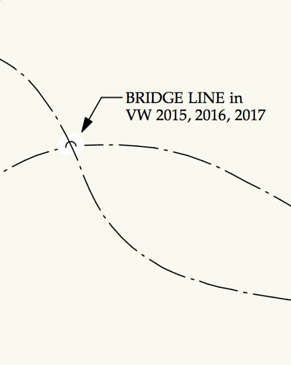
Please fix the bridge line tool. It should NOT have white fill behind the arc. It should only have white fill behind the line between the ends of the arc. The tool is unusable in its current state. We have dozens of these on our electrical plans and we have to delete them all. This has been an issue for the last three versions of Vectorworks. It was correct in version 2014, why was this changed? Clearly after three versions, someone up there must not understand the use of this tool.

-
Improve the floating data display?
PeterT replied to barriescott's question in Wishlist - Feature and Content Requests
This does not seem like a bug to me. When you DRAW anything the display is blue. When you use the tape measure tool you are not drawing anything, you are just measuring something. You cannot tab into the fields of the tape measure tool to change them because you are measuring the length of an existing object not setting the length of a object. ( i.e. The fields are not editable, so they should be greyed out like all other non-editable fields, this seems consistent to me). -
Oops, you are right. I guess I downloaded it from somewhere.