


Kevin McAllister
-
Posts
5,158 -
Joined
-
Last visited
Content Type
Profiles
Forums
Events
Articles
Marionette
Store
Posts posted by Kevin McAllister
-
-
15 hours ago, EAlexander said:
@Kevin McAllisterUgh. Every time I bring a lighting rig into Cinema4d I have to either refocus and reposition (hanging angle) every unit, or have them oriented correctly and have each individual light be a unique piece of geometry x 600. It makes me weep. Sorry to hijack the thread.
I know the issue. I have the same problem with scaled symbols, which ungroup to unscaled symbols..... I wish there was an ungroup to current state.
Kevin
-
 1
1
-
-
On 4/6/2023 at 5:45 AM, Tom Klaber said:
Rudina from my office - had a crash - very common - but when she opened the file - including all backups from before this happened - a subset of all the dimensions she had just spent the last 2 hours putting on moved and rotated themselves.
.thumb.png.d4c4b03e6b13fda4cb4556cb08b62320.png)
This happened across 20 different sheets. I can think of no mechanism for this. It took her an hour to put everything back together. Does anybody have any idea on what would cause this? It feels like we are paying for Vecotorworks twice - once for the subscription - and again in all the hours dealing with glitches like this.
That's super weird. Hopefully someone investigates it.... I don't like redoing things because VW misbehaves.
Kevin
-
20 hours ago, EAlexander said:
Command + K will take them back to symbols, but if they were focused as lighting instruments, they will lose that data and go back to how the symbol sits in x, y, z.
Not really helpful behaviour, is it.....
Kevin
-
 1
1
-
-
Bumping this. Still seems to be an issue in SP4 😕
Kevin
-
1
-
-
16 hours ago, Pat Stanford said:
Are you rendering in Shaded? If so check the Shaded options and make sure the Detail level is set to something other than Low.
Hi Pat.
The background render is shaded and the detail level is set to very high. It affects the polyline based extrude but not the oval based extrude.
Kevin
-
Hello all,
I had some weird behaviour with some geometry tonight becoming facetted. I use the same file settings and its been a long time since I've had facetting issues. I'm wondering if something changed with the most recent service pack.
This is where I started noticing the problem with an extruded oval. Notice how different the background shaded render is from the foreground hidden line. When I went in and edited the oval to turn it into a polyline (cut it in half and then added the surfaces back together) the issue went away.
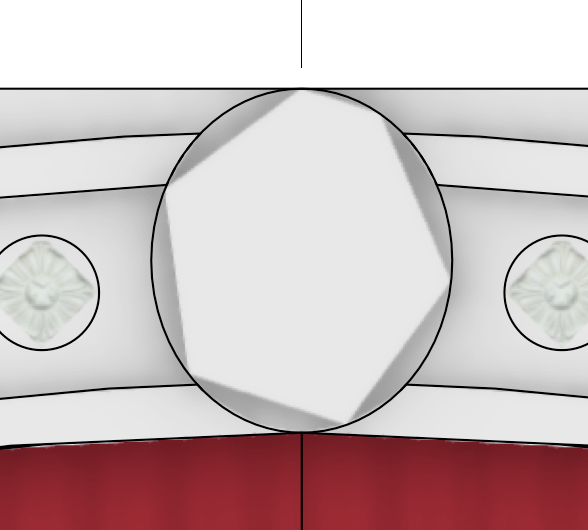
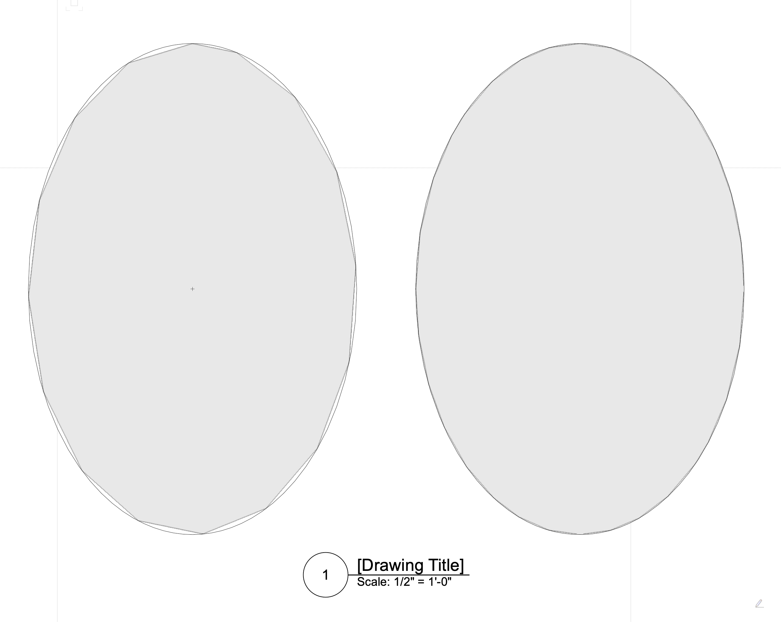
So then I did a quick comparison in a clean file. Both started as ovals but the one on the right was converted to a polyline using the method above. The facetting is quite different. Shouldn't standard geometric shapes (ovals, circles etc.) render better, not worse?

It's all very odd to me.
Kevin
(Its not related to either 2d or 3d conversion resolution which is where I started my troubleshooting.)
-
2
-
-
There was a wishlist item about this long ago. It would be better if they remained whatever they were before creating the EAP.
Kevin
-
23 hours ago, _James said:
Most tasks are single core processes only, so they can't be spread across the 8 cores you have.
I would say some tasks are single core. There has been a lot of work in recent years to migrate the code across. There definitely are some bottlenecks but its much better. @JuanP or someone from NV may be able to provide more information as to which items are still single core. I suspect snapping, some selection highlighting, math and a few others are still single core.
Kevin
-
1 hour ago, AlanW said:
@RideHi here i converted to 3D polys.
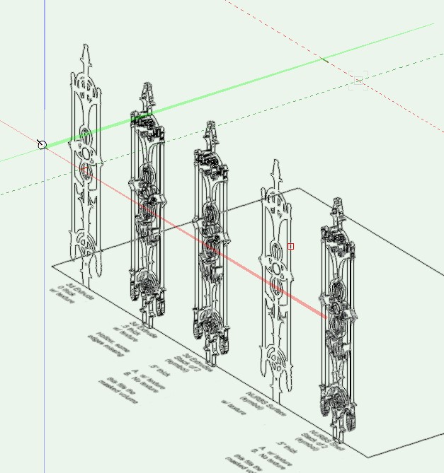
Alan, it's great that you're sharing advice, but it would be more helpful if you read the original post carefully and answered the question, not just throw random partly related suggestions into the thread. The original post asks how to break up the object into individual pieces with the appropriately mitred corners to share with a joiner.
Kevin
-
1 hour ago, Ride said:
@Kevin McAllister, your example seems perfect for what I'm trying to do. But can't get the loft surface to work. I assume I use 'no rail mode', but it doesn't work for me. Can you walk me through how to create the loft surface?
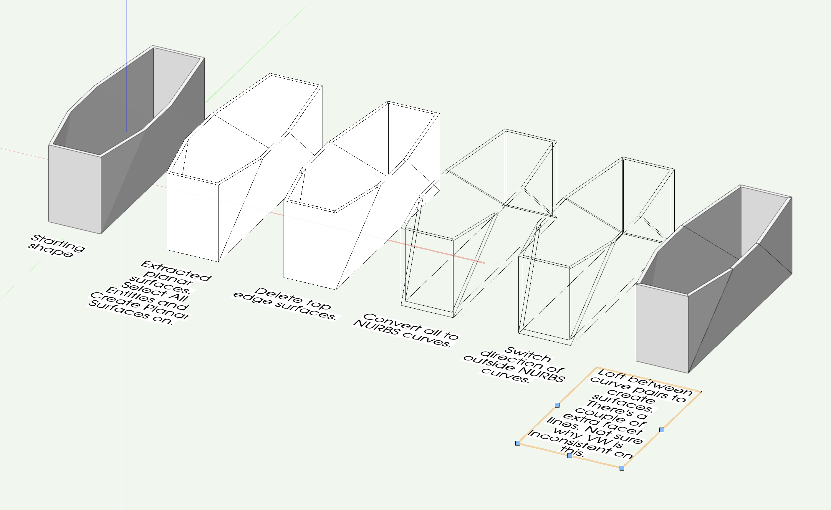
Note that you need to convert the planar (2d) surfaces to NURBS curves, not NURBS surfaces. That's why I extract the planar surfaces rather than just convert the original object to NURBS which results in surfaces. Lofting only works with NURBS curves.
Kevin
-
Here's an example file of how I would approach it. I've included both VW2023 and VW2022 versions since your signature shows VW2022.
The great thing about lofting is you can go from curve pair to curve pair without switching to the selection tool to select the curves you want to work on.
KM

-
3
-
-
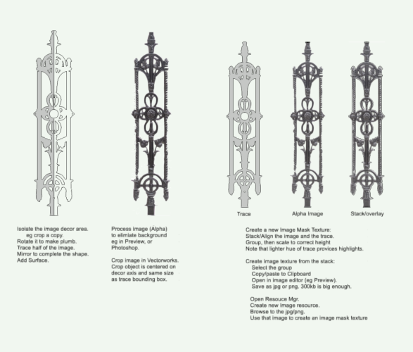
The easiest way would be to draw the missing surfaces. Make sure your plane is set to layer or automatic and you'll get the correct snaps. Then use Stitch and Trim to create solids. Alternately, you could extract all the surface as planar polylines, convert them to NURBS which creates NURBS curves, and then loft between the pairs of NURBS curves to create solids of each piece.
Kevin
-
1
-
-
I use paste in place all the time. Is the earlier version you're testing in pre-layer plane / screen plane? I usually only see anomalies in situations where the user origin has been moved, inside symbols (moving to or from), inside extrudes (moving to or from) and sometimes when the plane you were on doesn't exist (eg. pasting from sheet layer to design layer or the other way).
Kevin
-
3 hours ago, zoomer said:
OK, I did it too on my M1 Mini.
Seems like something to bug submit to find out why it's happening.
KM
-
2
-
-
17 minutes ago, AlanW said:
@Benson ShawHi opened in 2023 and was ok immediately.
Alan
Allan it doesn't look like you're rendering it in hidden line, which is were the anomalies show up.
Benson, I only get one of the two anomalies on my system.
Kevin
-
1
-
-
I would encourage you to submit it as a bug. The only way the tool will get better is if someone looks at it.
I have had accuracy issues with unwrapped surfaces in the past and tend to use Rhino now and export back to Vectorworks. Accuracy is important 🙂
Kevin
-
7 hours ago, Benson Shaw said:
Suggestions? Lost Cause?
thx
-B
Do they show up in sheet layer viewports? I've seen stuff like you're showing in some of my models. They tend to be ok in sheet layer viewports rendered in hidden line.
Kevin
-
1
-
-
I've never seen this option. I regularly need to align textures across multiple objects. Usually I use the Attribute Mapping Tool and snap textures to a common point.
Kevin
-
43 minutes ago, Andy Broomell said:
I was just thinking this the other day. It'd be very handy if viewports had a setting to determine the open state of Doors & Windows, with the following options:
• By Object (default)
• All Closed
• All Open
Perhaps it could be under Advanced Properties.
This would be super useful. I'd almost wish for multiple states for all objects..... rather than just for doors.
Kevin
-
5 hours ago, Benson Shaw said:
Such a good how to by @Benson Shaw!! Love it. This is how I would do it too.
Kevin
-
2
-
-
- Popular Post
- Popular Post
There should be a simplified Bug Submit form for anyone who has an online account with NV. That would make the first three fields irrelevant. If you could Bug Submit directly from Vectorworks, then entering your version / service pack would also be irrelevant.
I dislike that the system doesn't copy back your submission to you, so you have a record.
Kevin
-
6
-
It does it for me here, but only in perspective. It may be a bug but I've seen something similar happen in C4D. I think its related to how the viewport camera works in perspective.
Kevin
-
2
-
-
6 hours ago, Andy Broomell said:
I like your simple colour palette!
KM
-
2
-
-
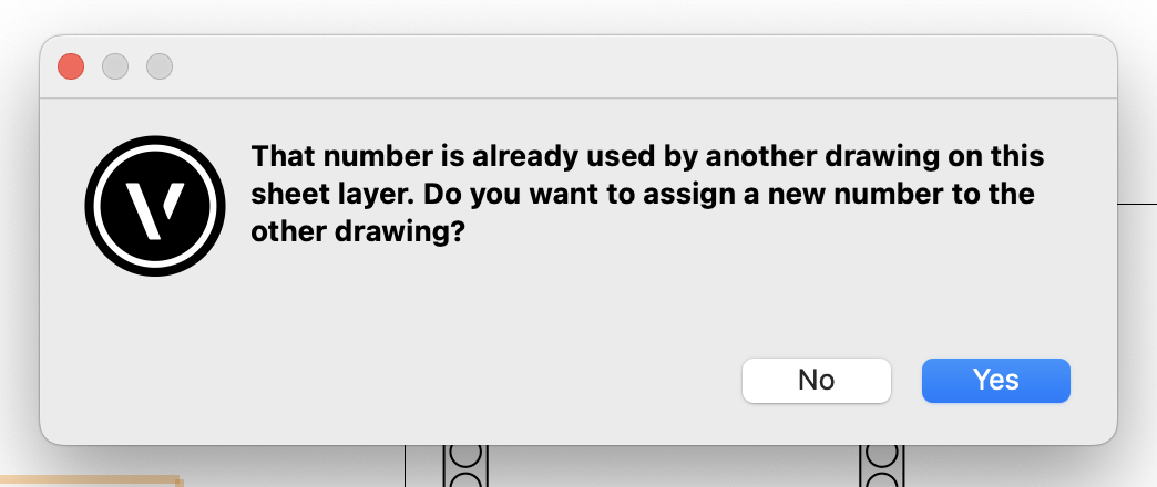
I wish this dialog that pops up when you're renumbering sheet layer viewports and you try and reuse a number would have a "always do the selected action" checkbox. My answer is always yes and I never want to see this dialog box again. As I renumber viewports I can see the whole sheet and am aware of my choices 🙃
Thanks,
Kevin

-
1
-
.png.fd6f2b8e0a7d7cf45a29a97bdb5d1b06.png)

How can I convert multiple lighting device objects back to symbols
in Entertainment
Posted
Nope. Reread the thread and you'll see why....
KM