Search the Community
Showing results for tags 'user origin'.
Found 6 results
-
Hi All, We need to align our landscape model with the architect's model and engineer's. Our model is aligned to true north - theirs to orthogonal on the x/y axis of the software. I can position our model in the correct location (very near Internal Origin) while retaining true Northing and Easting readouts by setting the User Origin where it needs to be relative to the Internal Origin. Problem arises where I need to rotate our model to align with theirs. User Origin coordinates do not rotate with the model obviously. Is there a way to not only move User Origin to maintain true project coordinates but also rotate User Origin to compensate for our model rotating to match theirs? Thanks Jack
-
 Hi Team. In previous versions of Vectorworks Landmark the User Origin is recognised by the shapefile importer & exporter as the 0,0 point for GIS data. This allows shapefiles to be generated directly from drawings which have an offset User Origin through a previous CAD file import (eg. from a civil engineer or surveyor). You simply georeference the layer to the coordinate system of the received CAD file, and export. It also allows a shapefile imported into an existing drawing based on a previously imported CAD file to appear in the correct position, provided that the shapefile and the CAD file share the same coordinate system. In Vectorworks Landmark 2020 I've found so far that both the shapefile import and export functions ignore any User Origin settings, and handle GIS data relative to the Internal Origin only. This prevents a shapefile from being correctly exported from a drawing with an offset User Origin (through previous import of a surveyors CAD file), and results in shapefile data imported into drawings with an offset User Origin appearing at the wrong numerical coordinates within Vectorworks. Perhaps for technical reasons the introduction of the new Geolocate and Geoimage tools required this separation of GIS and CAD workflows, but it certainly seems like a step backwards in terms of CAD/GIS integration. I'd be interested to hear other's thoughts.
 -
Is there a way to move a GIS stake to a defined co-ordinate position? For example, with a normal stake, you can place a stake, and then amend the X, Y details to move it to an accurate position. Can you do the same with a GIS stake, to identify a particular co-ordinate position, i.e. 257850E, 667750N (British Grid) - without having a line or point on the drawing already in this position to snap to?
- 28 replies
-
- 1
-

-
- gis
- georeferencing
- (and 3 more)
-

UCS not on building, so flyover tool makes building shoot away
jwaterhouse posted a question in Troubleshooting
Hello everyone, I want to use the flyover tool to see my building from all angles as I develop the design. The trouble is, the building is 50m away from the internal origin, which seems to be the centre point that the flyover tool rotates around. I though it would be possible to move the centre point of the rotation for the flyover tool without affecting the user or internal origins, but I can't find how. I have moved the user origin onto the building but it didn't move the flyover centre point. So from this I deduce the flyover centre point is fixed to the internal origin. Please let me know how to centre the flyover tool without moving all the elements manually to the internal origin. Thanks Justin Sorry everyone - I have answered my own question! The flyover tool appears to centre on an average position at the centre of elements in the drawing. So if you are working towards the edge of all your elements, which are for example 50m wide, place a sacrifial element 50m further away. It will then centre the flyover tool over the area you are trying to edit and will scroll around that point. You might need to move your new element around a bit to make the flyover tool be precisely where you want it, but at least this will stop it from shooting off the screen. You can then delete your sacrificial element once you have completed editing. -
Hi, wondering if anyone has any advice -- Sorry for the cross post; I was in the wrong topic area before. I have a plugin that includes a control point that is draggable, but which also exposes one of its coordinate input fields in the OIP to allow the user to type a precise value. When the user origin has been dragged, typed values in this field get offset in ways that lead to "incorrect" values, but dragging the control point behaves as if the current User Origin is the Internal Origin. I imagine I could use GetOrigin() to find the offset and fix this behavior, but how do I detect whether the parameter changed from a drag operation (in which case I should leave it alone) or a typed value in the OIP (in which case I need to fix it)? Or is there a way to get Control Points to only look at the user origin? (the documentation on plugin parameters would suggest not) thanks
-
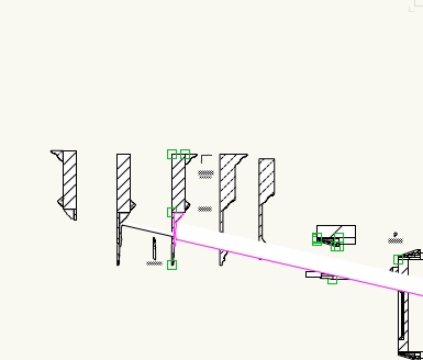
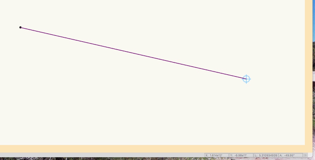
A college sent me a file to see if I could figure out what is going on. Here is the issue: - This person works in 2D exclusively - Somehow the User Origin has been set to a place several Angstrom Units South East of the Centre of the Drawing - The issue seems to involve a number of curves associated with some cornice molding profiles- when I change the fill & colour one of the arcs has a centre point at this odd location - Using the original profile to to Clip a shape results in the same issue - Brining the shape into a new file, eliminates this issue however; bringing back from the new file reestablishes the problem - Exporting to a DWG & Reimporting doesn't help Other than some JPGS & PDF there is nothing that has been imported. My friend is in a bit of a panic, if anyone has some advise I know he'll be grateful