


TaylorK
-
Posts
54 -
Joined
-
Last visited
Content Type
Profiles
Forums
Events
Articles
Marionette
Store
Posts posted by TaylorK
-
-
Hmm It looks like you've been creating a seciton viewport on the design layer, I haven't done that before and wasn't aware that it was even possible. My guess is its someting associated with that. You could try moving those seciton viewports for the set to the sheet layer, Seems to have worked in my test (basically just created a section viewport on that sheet layer and aligned it with your viewport behind Bottom section is where I tested this.)LFN 2024 Lighting Plot SJS.pdf
-
Any idea traction on this by chance? Feels like this is really needed for dropped ceilings & insulation.
-
26 minutes ago, BrettMac said:
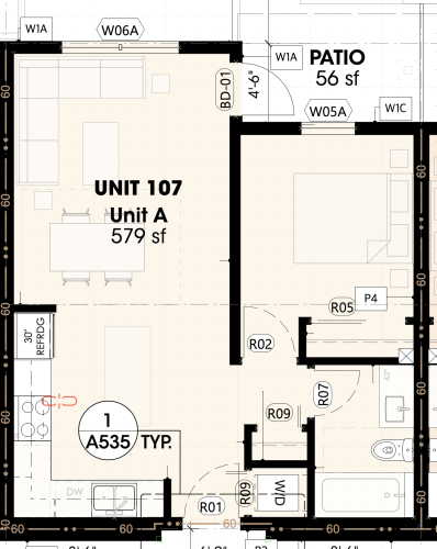
Can you clarify how you change between world and page based units for data tags? Our current wall assembly tag appears to be world based (red text in resource manager), and we're having trouble with the tag size becoming very small depending on the scale of the viewport. As soon as you "touch" the tag it reverts to the correct size, but it's annoying to have to shift every single assembly tag before we export. I've attached a screenshot as well as the affected file.
On a related note, does Vectorworks have a recommended workflow for projects with repeated unit layouts (ie hospitals or multifamily)? Currently we are setting up our unit layouts as symbols so we only have to change them in one spot, but when it comes to tagging/annotating we're running into issues like our assembly tags. Similarly, often times our styled walls refuse to show any height when inside a symbol. Should we be setting our unit layouts up differently? Apologies for the run-on question but I have a suspicion all of these issues are related...
Any help would be greatly appreciated
Hi Brett,
I haven't been able to get tags within symbols to scale either. For repeating unit layouts here is a thread on the topic. We're using symbols as well as we like to attach unit data to them and organize them in a worksheet but we're running into the same issues. As well as some issues with project sharing resettting walls. Recommendation is to strip out any storey based information from your symbols and manually set your wall heights. So basically demising & exterior walls outside symbols, unit walls/doors & fixtures in symbols. They're currently researching / looking to impliment a repeated unit tool. Hopefully that comes soon.
-Taylor
-
On 12/21/2023 at 11:45 AM, Matt Panzer said:
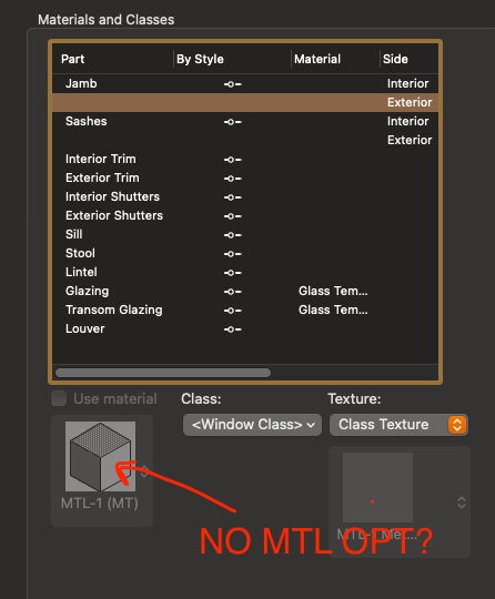
The material is what the jamb or sash is made of and jambs and sashes are not made up of different materials between the interior and exterior sides. This is why only one material can be used. It's only the finish that might change between the interior and exterior so this is currently done by choosing a different texture for each side. Since the door/window cannot have a different texture on different sides of the same object, it creates separate pieces for each texture. We realize this is not ideal and do want to handle this better in the future.
I can get behind that logic makes a lot of sense. Yeah would be ideal if the section were shown as one piece in that case.
-
 2
2
-
-
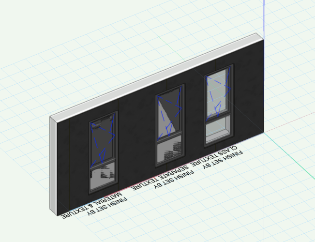
Im having the same issue. Setting the texture by class works to fix the problem but this can be problematic in section and isn't clean.
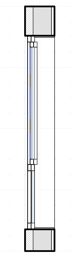
Too many lines
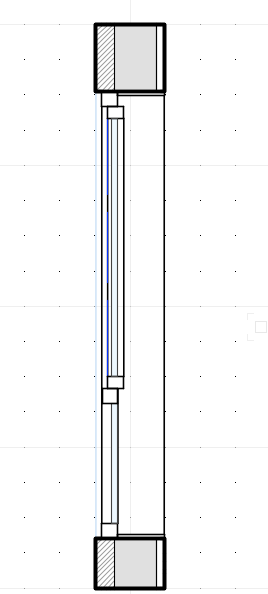
What would be nice for it to look like with different textures for int / ext.
Seems odd that we cant assign different materials to the interior / exterior Sash & Jambs. It would be preferable to have the jamb and sash for interior / exterior on the same class so the section is cleaner & set the appearance by material for those independently using material.
-
1
-
-
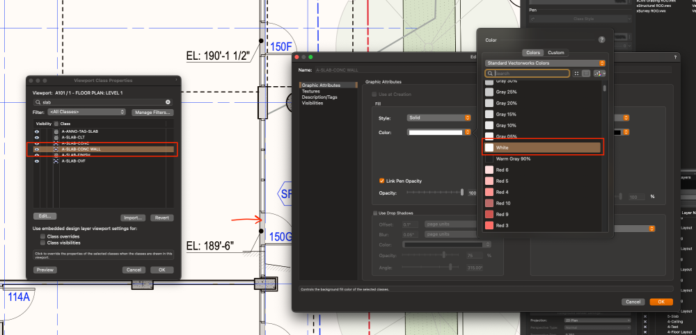
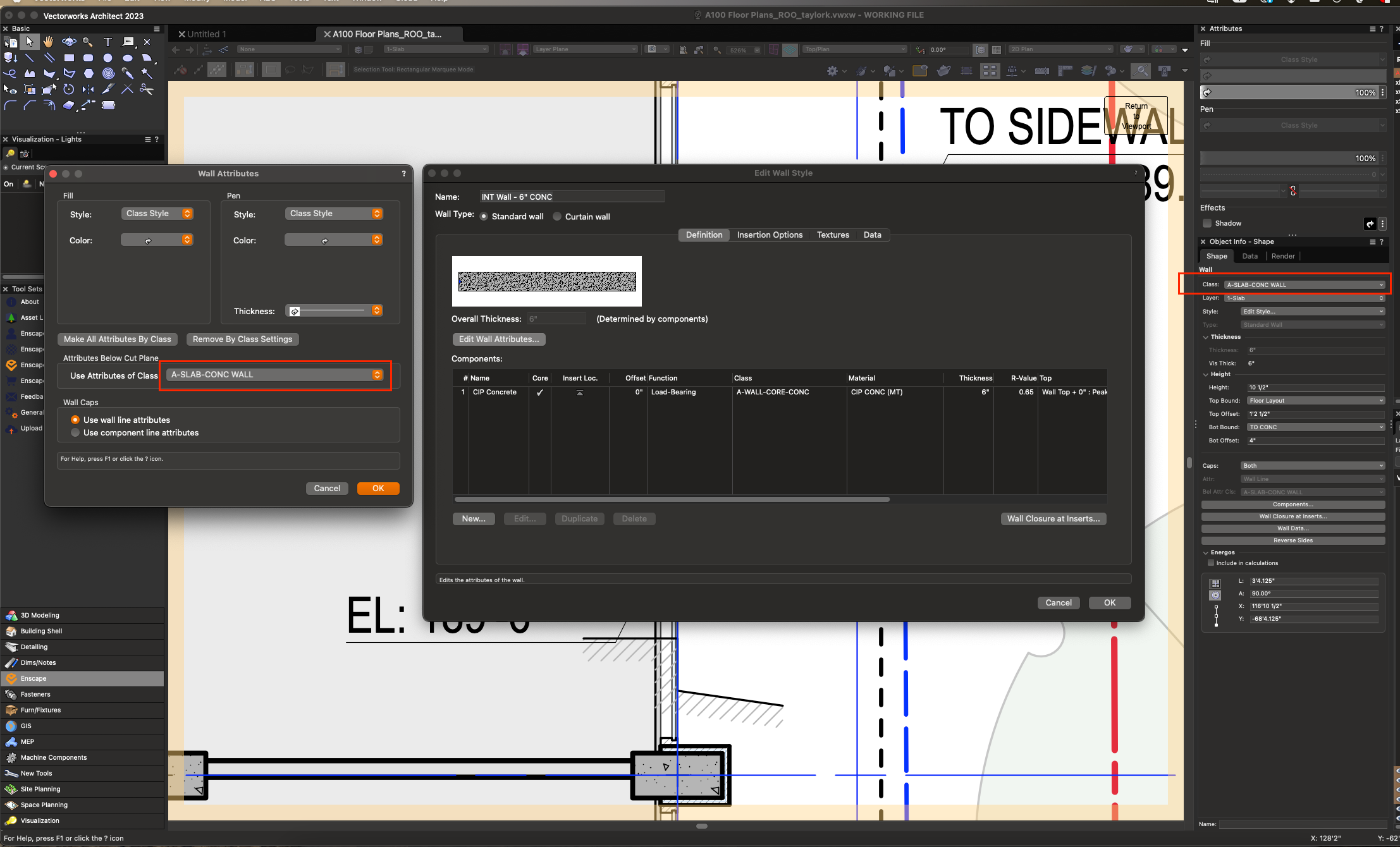
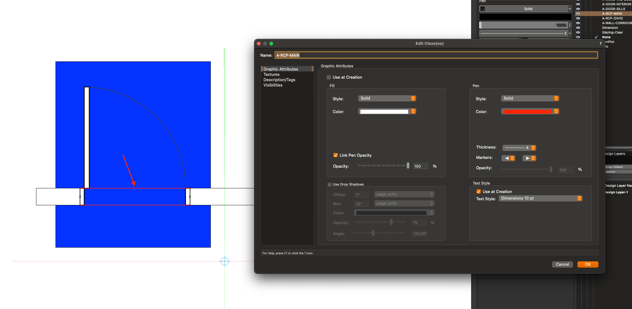
It seems that walls that have their view properties set when they are below the cut plane stop obeying viewport override settings.
In this example I have a stem wall thats is below the cut plane and has its attributes set to a different class as the wall. In a plan viewport I have that class set to override the fill and it doesn't seem to update the visual properties. This persists even if I change that walls class to said class for below the cut plane.
Is anyone able to replicate this issue? I've attached an example file to demonstrate.

-
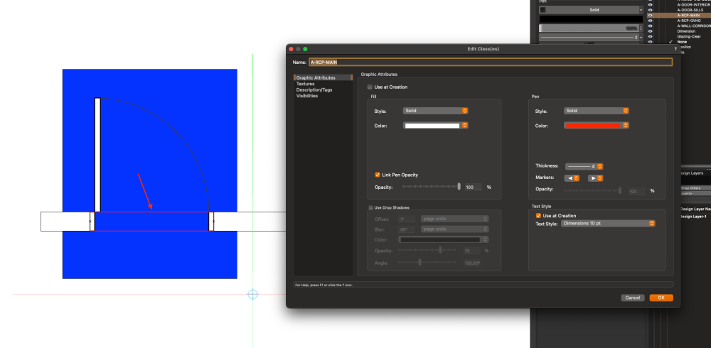
Bump in this, is it really not possible to add a fill for the Wall lines / Header class?
-
Bump on this feature! Would be so useful for facilitating a better bim workflow!
-
It seems like a material override through data visualization doesn't work as expected on Columns.
Here's an example of a data visualization set to override concrete material to be no fill (you can see the walls at the top it works as expected.)
Here are the settings for the column style & data vis.
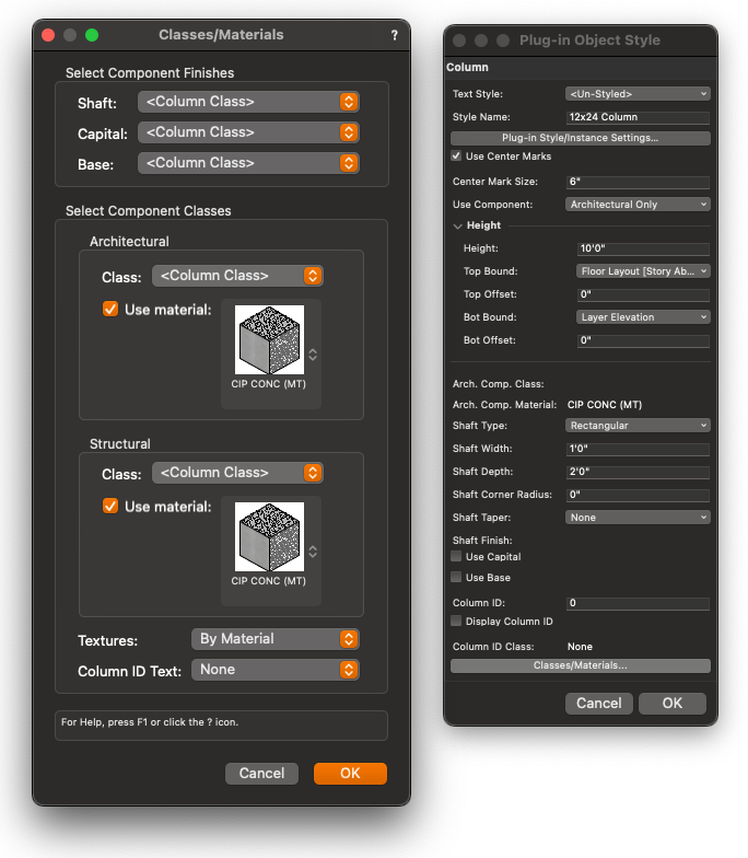
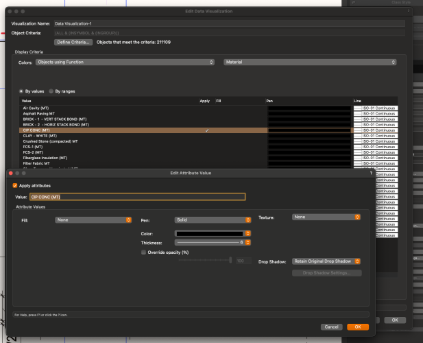
Is there something Im missing here?
I've also attached an example file.
-
Agreed Hidden line mode should show surface hatch fills!
-
1
-
-
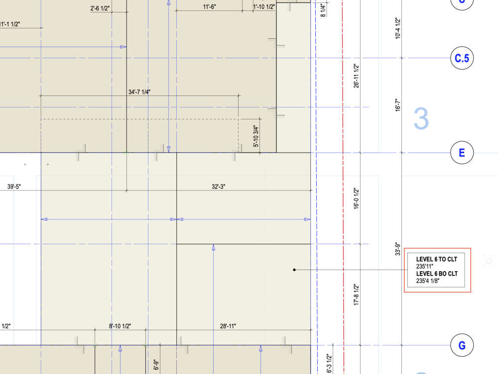
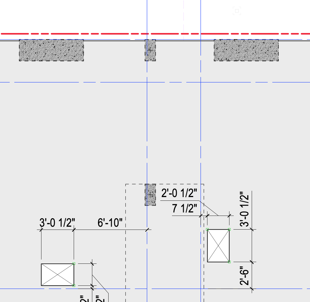
Is it possible to tag an object relative to a given datum? ie if you're making a RCP and want to tag a slab object on the story above and get the Z value relative to the lower storey? Seems like the Z bot only gives the value relative to the storey that object is associated with.
-
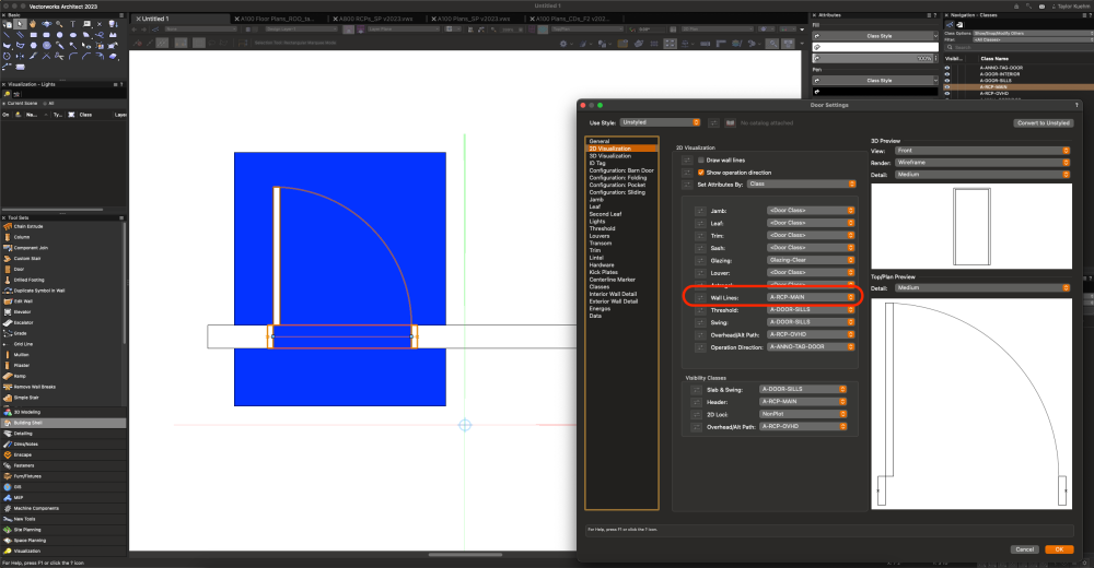
It seems that you can control the Wall lines / headers of doors in the plugin options by class, but for some reason the header doesn't fill in? Seems like this would be pretty necessary in RCPs? Is there a work around for this that doesn't require drawing rec over every door way?
-
The work around for this if you want to fully color'd drawing is to render the background out as shaded without textures on, and have hidden line as the forground. But I agree would be nice to have selective background fills on the hiddenline only drawings as for example we like to shade concrete in our typical elevations.
-
If you want to create a fresh project file from your working file. You can do a file/save as from the working file and save it as a regular .VWX file. Then open that VWX file and make it a project file. Hope that helps.
-
Is it possible to cut a shaft through multiple slab objects at once? AEC-Subtract 3d object from slab doesn't allow you to select multiple slab objects. Is there another way around this?
It would be very handy to be able to link a whole shaft cut to one object rather than having to cut out the area for each slab object per floor, and would make coordination/updating shafts easier. Thanks!
-
Posted it here if anyone wants to upvote.
-
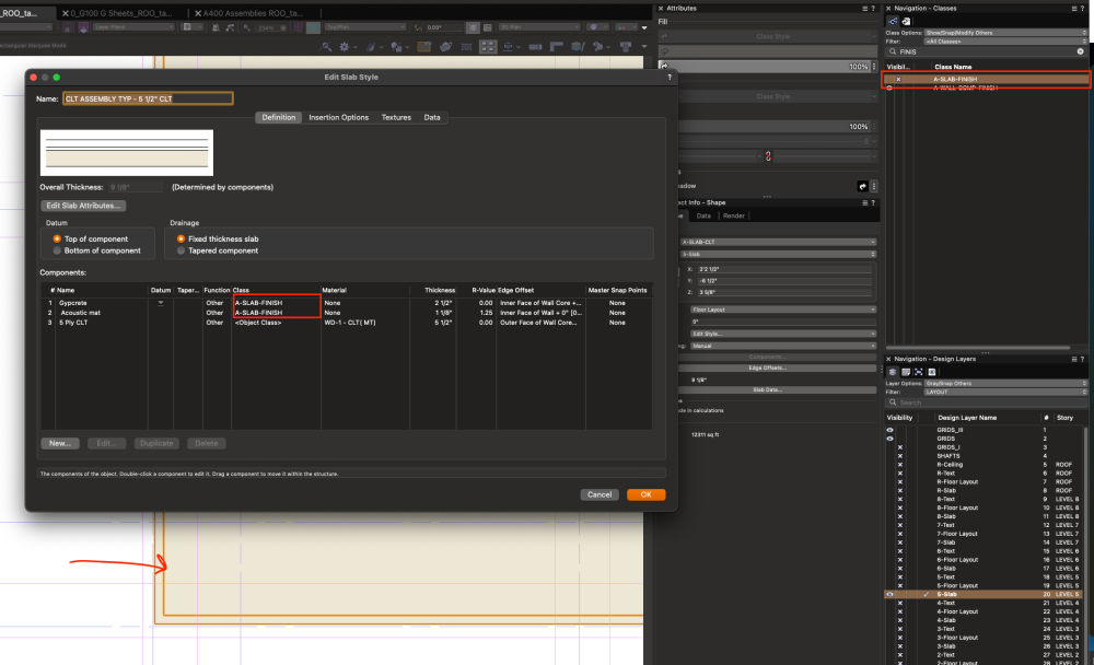
Per this post, allow users to turn off classes of slab components in top/plan view. Should streamline coordination and documentation greatly limiting the number of slab objects required and coordination between shaft cuts.
-
1
-
-
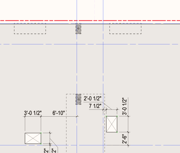
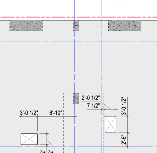
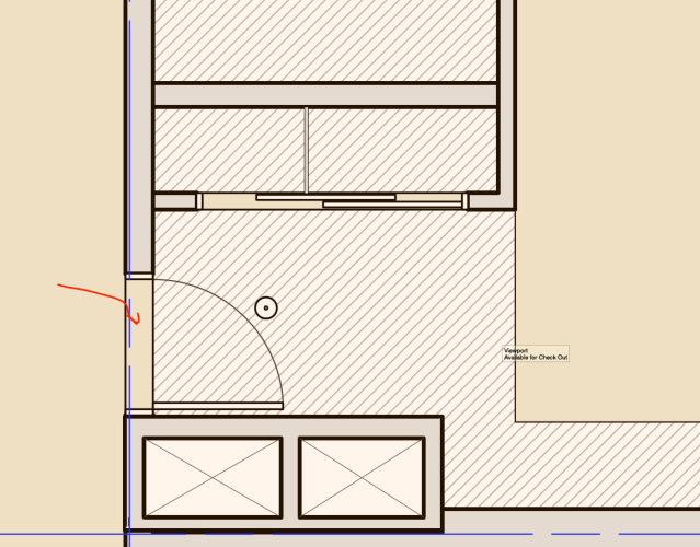
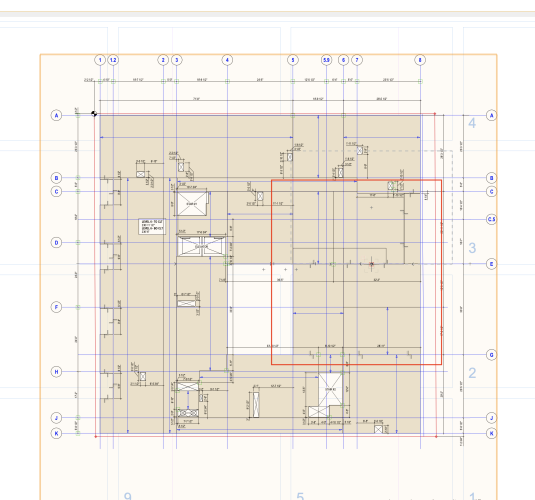
When using edge offsets in plan VW draws components in top/plan view when classes are off. Would be nice if when those classes were turned off that they would also not show in plan. Is there a work around for this? Is this working as intended? I know I could simply model structural objects separately from finishes ie. separating out CLT slabs from Gypcrete & other components but I feel this adds a lot of additional work coordinating shaft cuts ect.
-
1
-
-
Hi @emilie,
We've been having this same issue since updating to 2023, though it seems to just be a in software visibility issue for us. If we publish the sheets it works as expected and will print the classes that are on in the viewport even if they're off in the OIP. Though is obviously still an issue, we usually have a "Print" saved view that we use right before publishing and has all the print classes on for this reason.
-
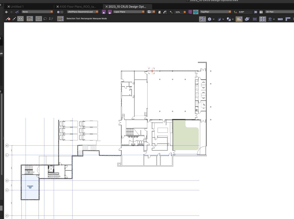
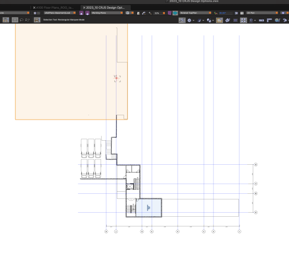
When working with rotated top/plan views referenced viewports seem to bug out and become non visible. Issue is repeated across multiple computers. Viewport will reappear when panning and zooming.
-
Thanks for the help @Pat Stanford, I was able to make a data tag that reads the top and bottom of a slab object and reads the Z relative to ground as well as the storey. Only downside is that the CLT or slab needs to be modeled separately than the rest of the floor assembly, ie finishes or subflooring. Though if anyone knows a way around that let me know.
-
Well I seem to have fixed this by recreating the slab from scratch with the same settings.... so not sure what caused it.
-
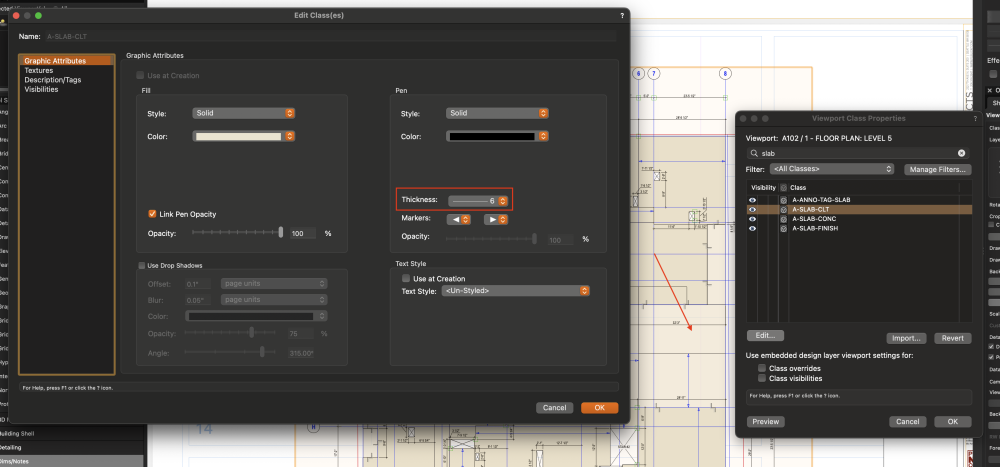
It appears that when using class overrides and slab objects all attributes of the overrided are applied when a single property is changed.
ie. If lineweight is changed it also overrides the opacity of the slab. (as you can see changing the lineweight overrides opacity of this slab object.)
This isn't the case with 2d objects which will keep properties that aren't overridden. So not sure if this is a bug or not?

-
Thanks Pat! I'll take a look.


Section Viewports Not Appearing in Published PDF
in Troubleshooting
Posted
On second pass it seems that when a sheet layer viewport is rotated this causes the design layer section to not print/ rotate correctly. Here's an example one rotated one not and you can see the one without plan roation print correctly.
You'll need to rotate everything in the design layer so you wont have to rotate the viewport on the sheet layer.
LFN 2024 Lighting Plot SJS_ROTATE TEST.pdf