AlistairM
-
Posts
29 -
Joined
-
Last visited
Content Type
Profiles
Forums
Events
Articles
Marionette
Store
Everything posted by AlistairM
-
Please contact me at alistair@harmoniaconsulting.co.uk if you are interested.
-
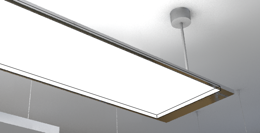
I hope someone knows what I'm doing wrong here... I have an area light source as part of a lighting fixture symbol. This looks fine in shaded mode, but when I use a Renderworks mode (e.g. Realistic Interior Fast in the screenshot below) the glowing part shows a black edge, even where it is behind other objects. Do you know how I can turn off the black edge? I have tried unticking 'Render geometry' but that didn't help. Thanks!
-
To answer one of my own questions... I see that the 2d component of a hybrid symbol used for an Equipment Item is visible once it is connected to a Drop Point.
-
I'm trying to find the best way to make this workflow work: I design my layout using generic symbols to represent AV equipment Once the layout is agreed, I design the connectivity in Connectcad I can use symbols for the Equipment Items to make them look the same as the existing drawings objects. It is quite a laborious process though to do this and then to move them to the same coordinates and to re-associate data tags that were on them. Is there a way of doing the process the other way, by converting the symbols to Equipment Items? Or a way to associate an equipment items with a generic symbol (like it can be associated with a Spotlight object)? Or even a quick way to move one object to the position of another (these are complicated symbols and it takes time to find a geometrical feature than can easily be snapped to)? I see also that the Equipment Item only displays the 3d component of a hybrid object. Is there a way to make it show the 2d object? And finally... I have imported design layers from a schematic drawing to the layout drawing. I see that the Room Layout outlines have been renamed, and the locations indicated on the schematic doubled up, e.g. what was 'Wall' has become 'Wall - copy.Wall - copy'. This can be fixed on an individual basis, but does it indicate that I have imported the design layers incorrectly?
-
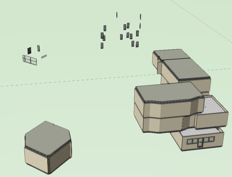
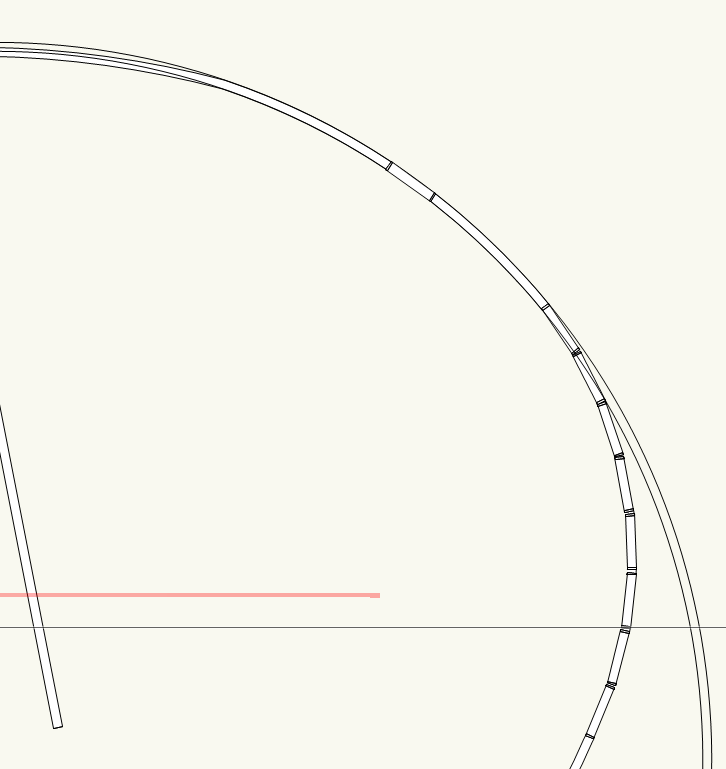
I'm having a problem with doors and windows too - do you think it's related or something I'm doing wrong? I have a building in one file, which I copied into another file using layer import. In the original the doors and windows worked properly. In the new file, when I select and move the whole building most of the doors and windows don't move. Moving them individually to the new location doesn't work either. It looks like this after the move:
-
Thanks for looking at this Matt. Please see the attached file. 1518801477_Curvedwallproblem.vwx
-
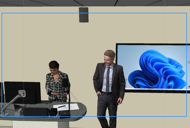
Is this is a bug with the video camera tool or am I doing something wrong? If I put the video camera on a layer of 1000mm elevation, I get this result, with the frame outline in the right place: The work-round I have found is to put the video camera on a 'dummy layer' with 0mm elevation (and adjust the z-coordinate so the camera ends up in the same place). Then I get the correct frame outline like this: So it looks to me like the video camera only works correctly if it is on a layer of zero elevation. Any ideas? Thanks
-
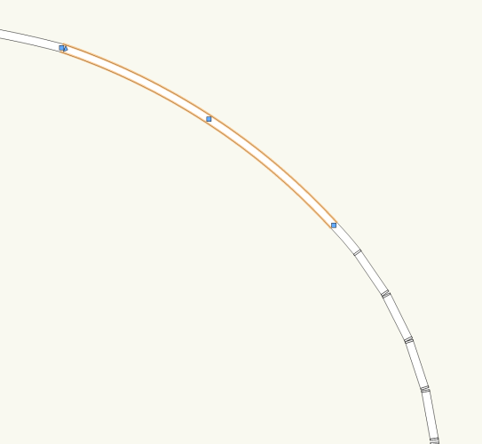
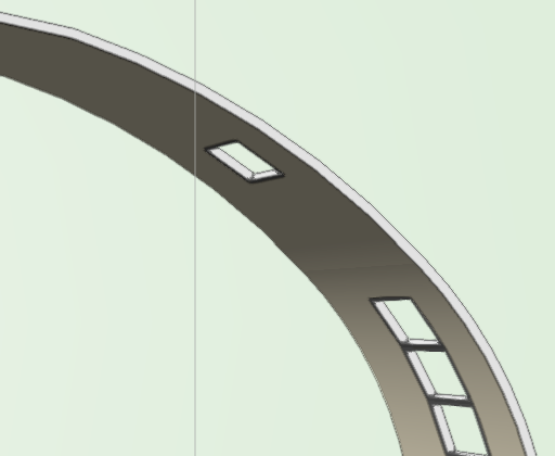
I'm trying to insert a window in the selected arc section of wall. I have already successfully inserted windows in the adjacent arc section. The trouble is that once a window is inserted, although it displays correctly in 3d, in 2d a circle is shown completing the arc like this: This will mess up my plan view, but I can't find a way to get rid of it without deleting the window. Any ideas what is causing this and how I can fix it? Thanks!
-
Hi Nikolay Am I right that it is not possible to change the attributes of the text without also changing the attributes of the equipment in the same way? It looks like they are in the same class. Thanks Alistair
-
Service Select Support - Add a Ticketing System
AlistairM replied to E|FA's question in Wishlist - Feature and Content Requests
Thanks Juan - that query was actually dealt with very promptly. But it would have been slicker if I could check the status on a portal rather than phoning to find the answer. I do have another open ticket that I'm sure is being diligently investigated, but again a live status indication would give some re-assurance. -
Service Select Support - Add a Ticketing System
AlistairM replied to E|FA's question in Wishlist - Feature and Content Requests
I also have received no acknowledgement of VSS support requests using the web form. The support service really is too slow for a paid service, and makes me question the VSS subscription. An accessible ticket system should be the minimum, so we can track what is happening with our request. Indeed it might save VW some work, as we won't keep calling to check progress if we can see what is happening. -
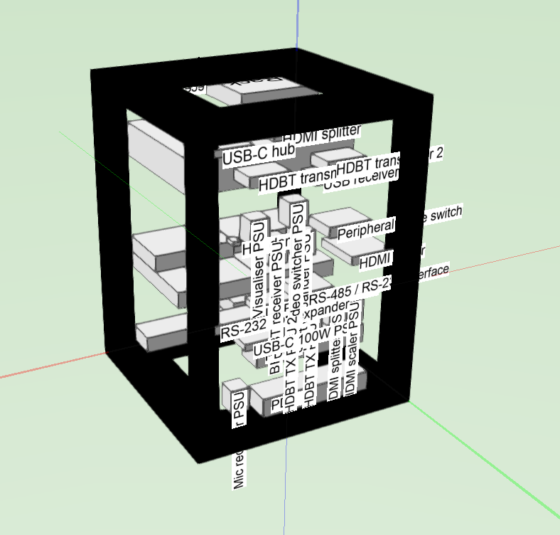
Is there a way to turn of text display on a 3d rack, like there is with the rack elevation? Or a way of controlling the text attributes would do the job. With lots of little boxes in the rack it looks a bit of a mess:
-
Grid settings for each layer
AlistairM replied to AlistairM's question in Wishlist - Feature and Content Requests
Yes, it could be done with a grid as an object, but I was hoping to be able to use the VW Snap to Grid feature this way. -
It would be very useful have independent grid settings for each layer. This would allow for example the grid to be displayed in the design layer, but not the sheet layer, or different grids in different design layers according to their function. Or is there a way to do this already?
-
Thanks Nikolay Now I understand why the offset values aren't there I'll use the control points.
-
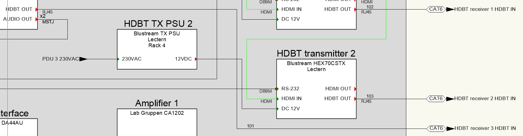
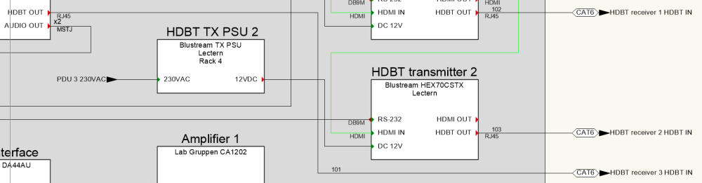
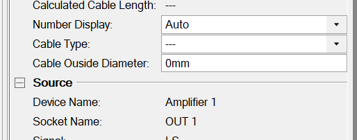
I would like to do something similar to requested above. In fact I have done it before but have no idea how as I can't replicated it for new cables. See cable 101 in the screenshot below. I would like more arrow circuits with the cable re-routed in a similar way. Any ideas how I achieved this in the existing part of the drawing and how I can do it again? Incidentally, I can't even move the arrow position using the OIP offset values as Nikolay suggests above (maybe that was the method), as they are not shown in the OIP:
-
Thanks Nikolay, that did the job. I've now managed to switch off legacy 2D.
-
Thanks for looking at this Nikolay. I'll send you the file to help you can understand the issue better. For the equipments with no drop-down - the problem is that there is no plane drop-down at all in the OIP, so I can't even attempt to change the plane. Does the lack of the drop-down mean the object is already in the layer plane?
-
I have a Connectcad schematic that was started in VW 2022. Somehow it has been drawn with all the device objects on a 3d plane and the connection objects on the layer plane. There were also some devices on the screen plane, but I have moved those to the layer plane without problems. If I move the devices to the layer plane, they change position in an apparently random way; their connections show no errors though, even though they do not appear to be connected to anything any more. The rack elevation layer is also confusing: some equipment objects are on the layer plane, and some of them do not show a plan drop-down in the OIP, so I don't know what plane they are on. I have 'enable legacy 2D features' switched on, and am prevented from turning it off. I would like to sort this chaos out before I base lots of other schematics on this one. So my questions are: Does it matter that I have this strange mix in the drawing or can I ignore it? If I am to fix it and move everything to the layer plane (the correct situation?) is there a way to do this without re-drawing all the connections? Any idea what I did to get the drawing into this state?
-
Hi @Conrad Preen I'm sure I used to use this command without trouble, but now I can't find it. I am looking under ConnectCAD > Layout, but all I see is Create Equipment... Is there some special condition (e.g. rack selected, which I have tried) needed to make this command available? Alistair
-
Best practice for setting up a project with multiple rooms/locations
AlistairM replied to elc's topic in ConnectCAD
I was wondering if anyone had figured out a good way to deal with multiple systems in a project yet. It is problematic when extracting device schedules or doing rack elevations, unless the same device in each room is given a different name. I feel like I must be missing a simple solution, as it's an issue that affects nearly every project! The two solutions I have are to either split into a separate file per system, or to rename all devices in each system (leaving the display tag the same). Both of these are quite cumbersome. Any ideas? Thanks, Alistair -
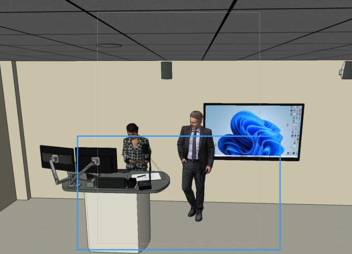
I've been working on this TV tool to give me some options that aren't available with the standard Spotlight one. It's WIP, but I thought I put it up here in case anyone is interested. You can set some parameters for a TV: screen inches, landscape / portrait, tilt, screen image, mount type etc, and it is parametrically adjusted. With a bit more work it should be able to use a symbol instead of a parametrically-generated item for the screen or mount, but I'm not quite there with that yet. I was starting to find Marionette a bit buggy and slow, and thinking maybe I should move into scripting instead. This would help control problems such as needing several 'update' presses to cascade some changes through as it does at the moment. Any thoughts on whether that would be a better plan? And any comments on the whole thing also welcome (my first complex Marionette object!) Thanks New TV tool 32A.vwx
-
One copy for sale £1600+VAT
-
Thanks for checking it out Pat. @Marissa Farrell can you figure out what's going on with my files?
-
It sounds like it could be a similar issue. I have another file here, in which I isolated a problem node. I suspect that this was to do with copying between files. Maybe this simple example will help identify the issue. node test 2.vwx