Carol Reznor
-
Posts
32 -
Joined
-
Last visited
Content Type
Profiles
Forums
Events
Articles
Marionette
Store
Everything posted by Carol Reznor
-

Candy cane stripe around Hardscape object
Carol Reznor replied to Cody Worthman's question in Troubleshooting
hi @Cody Worthman If this happens again, the way to get rid of it is to: in the OIP 1. set the configuration to Aligned 2. click on Update alignement so the candy-can-stripe disappears 3. then you can change the configuration to another configuration without having the candy-cane cheers -
hi @vassen If it is not the trees that are causing the 'slowness', try checking both your hardscapes and site model. what to check for in your Site model: is the Source data simplified enough for ease of use? For example when the source data consists of polylines, how complex are these? what to check for in your Hardscapes: - in the drawing: Are the paths of the Hardscapes (Boundary mode) properly closed? Sometimes it happens when you check the path within the Boundary Hardscape the line is not actually closed) - Can cause issues. - are the hardscape components defined by materials? Do these materials use a texture Surface hatch? Surface hatches can slow down the rendering of VP in my experience. I believe changing some VP settings in this case can help. Good luck!
-
Drone survey: import your pointcloud with correct georeference
Carol Reznor replied to Carol Reznor's topic in Site Design
@Tom W. That is a good practice I find and my personal preference to indeed set it (the user origin) back to match the CRS - especially if you export to DWG because otherwise the DWG will read what the rulers say and import incorrectly ( check the box export dwg with georeferencing puts a Geographic marker in the file in autocad) ... BUT for architects... if you want to export to IFC you shouldn't as IFC only works with 1 origin, so in that case they (internal and user origin) should stay in one place. hoop hoop hoop 🙂 -
hi @Jeff Prince I believe the only thing a Plant Label CAN do that a Data tag can't is show the Plant Image. Or has that changed and is that also possible now with a Data tag?
-
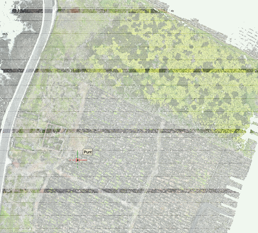
When you import a point cloud as is - without centering it on the internal origin as to keep it in its geolocation, you will get a point cloud that is visually corrupted, as in, it will have ugly lines... and the x,y coordinates say 0 while you can see in the rulers that is not the case... Some time ago I reported this as a bug. I think it still is, as this should work properly so not to loose the correct georeferencing and have a nice workable point cloud. The solution I found for this now is 1. import the geotiff generated by the drone (using the settings of the geotiff - units and EPSG) then 2. adjust the internal and user origin so they coincide with the midpoint of the geotiff and finally 3. import the point cloud ticking the box 'Center Import on Internal Origin' So - you need to export a geotiff and a point cloud from your drone to be able to use the pointcloud in GIS RESULT of 1-2-3
-
Hi @Katarina Ollikainen ! I have made a screen recording which you can find here As you can see at the end Vectorworks even crashes... Thanks in advance!
-
FYI - I am no longer working for a distributor...
-
Hi Not sure if this is related but ever since I installed the PlantMaster plugin the following is accuring. When I place a custom Plantstyle which has the Plantrecord attached from my library into a new drawing the Plantrecord disappears. And there seems to be no way to reattach the Plant record. Or is there a way? Please let me know how. Now i Just reset my Userfolder but the issue remains. Am updating the SP now, will see what gives. Also checked the data manager but am not 100% sure how the settings should look like default. Any one a screenshot of that? But just wanted to check if any one else is having issues... (it is 2 to 3 hours of work spent on trying to figure out what is going wrong while meant to be doing something else...) Thanks! Carol
-
Hi In a site modelling project these two parameters, height and slope, are frequently used and shown. They both have their own separate use. Is should be possible for both to have their own object attributes - in other words the user should be able to assign a class for example: - Height new or existing - Slope/grade new or existing WISH: 1. Open Edge Line, Planar Pad & Pad with Retaining Edge Add Assign Class option to the Planer Pad Slope settings. This makes it possible when showing the Slope value its appearance is consistent when using are Slope definitions in the file. This for the Site Modifiers Open Edge Line, Planar Pad & Pad with Retaining Edge and for Hardscape with Planar Pad configuration 2. Aligned & Path objects incl. Classes for Profiles, Longitudinal Profile, or Transverse Profiles Change the assign Class options so one can define the appearance of Slope and one defines the appearance of Height by adding: - Class Height values - Class Slope value - Class Profile Then the Show-option boxes can be deleted and replaced by changing the visibility of the Class. This allows these values to be shown consistently throughout the drawing and eliminates to need to set this separately for every single object. Thank you
-
Add Grade Def to Document settings: Units
Carol Reznor posted a question in Wishlist - Feature and Content Requests
Hi This is about the setting for Grade Def: Select the type of display for the slope (percent, rise/run ratio, or angle) WISH For consistency throughout the document/project It would be nice if the way the grade is defined (percent, rise/run ratio, or angle) can be set in File > Document Settings: Units, Scale and Grids. As a consequence: In the OIP of the object using 'the display for the slope' the default option then could be 'Document Units'. This eliminates the need to set this for every object separately. Also take into account linking the setting of Profiles, Longitudinal Profile, or Transverse Profiles. Thank you -
Hi We have set up a Workgroup folder that contains the Plant Database folder which includes: the TXT files and a folder with the linked Plant images. In Vectorworks Preferences the location we have added the Workgroup folder location. Now how can one be sure that the program is getting its information from that Workgroup folder and not the User Data and Preferences folder? The command 'Choose Plant Data Source' only lets you explore, not choose a different location... so, in conclusion, the default Plant data source is always the pointed to the User Data folder? So there is no way to work with the TXT based Plant Data, is that correct? Is there a specific reason for this? Is there a workaround so it is possible to work as a team using the Plant Catalog (txt based) and not with the Filemaker database? Thanks Carol
- 1 reply
-
- 1
-

-
Hi Alex Could it be that in the Landscape area settings the following is turned off: - In the 2D Display category the option Show plants in 2D is not checked? - or if it is 3D, in the 3D Display category the Show plants in 3D is not checked? Plant information is added I presume in the Landscape area style right?
-
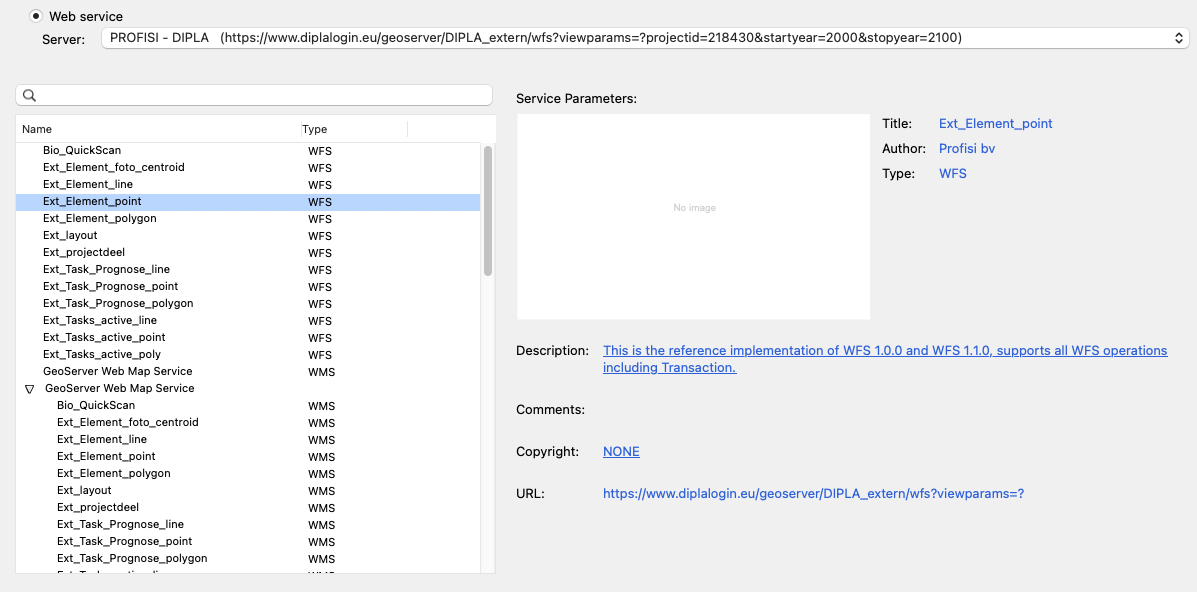
Same issue with the WFS services from the Belgian government (they have updated their services recently) Example: https://geo.api.vlaanderen.be/GRB/wfs CRS: Belge 1972 / Belgian Lambert 72 More info: https://www.vlaanderen.be/datavindplaats/catalogus/wfs-grb Could this be due to: Consumption and use of GML complex features like INSPIRE harmonised data (vector), GeoSciML https://schemas.opengis.net/iso/19139/20070417/gsr/spatialReferencing.xsd http://www.datypic.com/sc/niem30/e-ns65_AbstractCRS.html
-
How to let worksheet report plant count instead of "plant object" count?
Carol Reznor replied to DDD's topic in Site Design
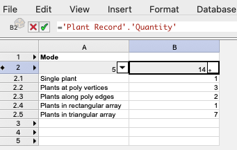
Hi Maybe instead of using the tag as a criterium you could use the following in your worksheet the Insertion options Mode (Formula for worksheet header: ='Plant'.'config') This will allow you to list or filter by how the plants were inserted as a single plant or as a group Carol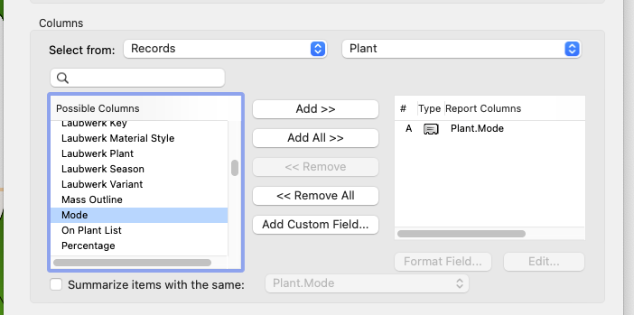
-
Hi When downloading content from a WFS Webservice I sometimes get back the following errormessage: CPLErr( 3 ), err_no( 1 ) /vsicurl_streaming/http://schemas.opengis.net/iso/19139/20070417/gsr/spatialReferencing.xsd:19:39 type 'http://www.opengis.net/gml/3.2:AbstractCRS' not found. You may retry with the HANDLE_MULTIPLE_IMPORTS=YES open option What does it mean? And what can one do about it? Thanks!

-
Hi Is there a reason why that Layers which are Georeferenced do not rotate along when changing the Orientation (angle to true north)? It is something I would expect georeferenced layers to do automatically. This would make it possible to change the geo-orientation of all georeferenced objects and not the objects on non-georeferenced layers. Now this option seems to be impossible: you either select 'Do not transform' or 'All (transform/move&rotate)'. What exactly is the difference then between layers checked as geo-referenced and others which are not? Thanks!
-
Hi - using the Diameter Variation (Plant Style > Appearance) could help you out if it is just a matter of Graphics? It adjusts the size of the symbol randomly. If you need exact diameters you will indeed need to put the plants in the drawing defined one by one.
-
Hi Is there a quick way to have your own set of Vectorworks 2021 Hardscape Styles, that are based on a Slab style, converted to the Vectorworks 2022 Hardscape Styles without losing the settings of the Slab components. A way where they retain their settings for Class (imports the Classes with their Graphic Attributes if set by Class style), Materials, Thickness, Texture, Section Fill&Pen? Another thing that no longer seems adjustable when creating a Style is choosing to set the Texture by Component or by Object. How to adjust this for an existing Hardscape Style? Thanks! Carol
-
ETID: SOLVED!!!! Lumion/Vectorworks materials best workflow?
Carol Reznor replied to NoemiM's topic in Rendering
@NoemiM Hi - I am curious in how you solved the problem you were having. You care to share? Thanks! Carol -
Hi When preparing a vwx file with georeferencing for export to a DWG - which typical (proprietary) Vectorworks features should you remove to get a correct DWG? First that comes to mind is: User Origin > Set User Origin to match the Georeferencing coordinate system But what about 'Angle to True North' - can this be properly exported and interpreted by other software or does this need to be reset to 0? Any thing else that could cause problems for a proper collaboration? Any file workflow recommendations for that? for example: in your vwx file you work with an angle to True north, the viewports are made etc. Then you need to share your design with someone who works with different software. Knowing this person will send you his file back with additional information you need to integrate in your vwx file. Is it recommended to make a copy that you strip from these Vectorworks features or is there another work around? Thanks! Carol
-
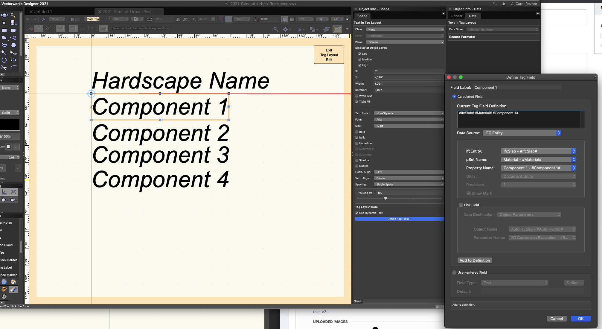
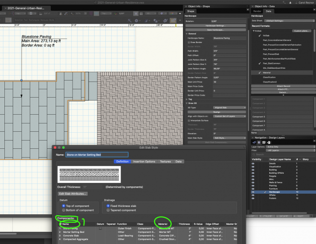
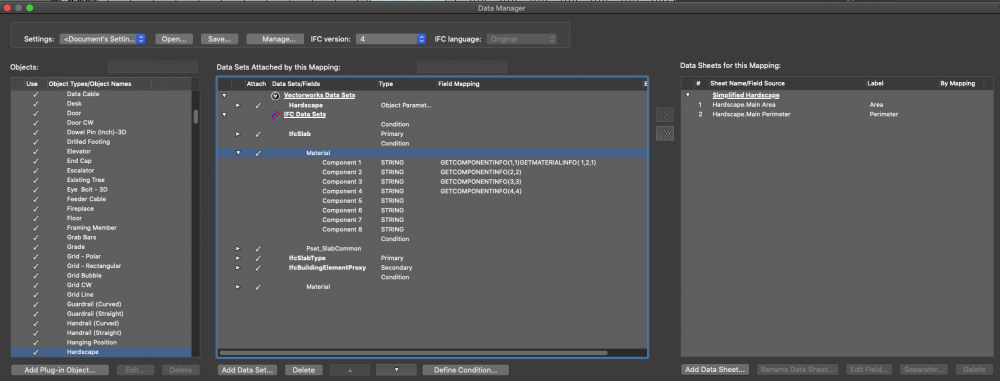
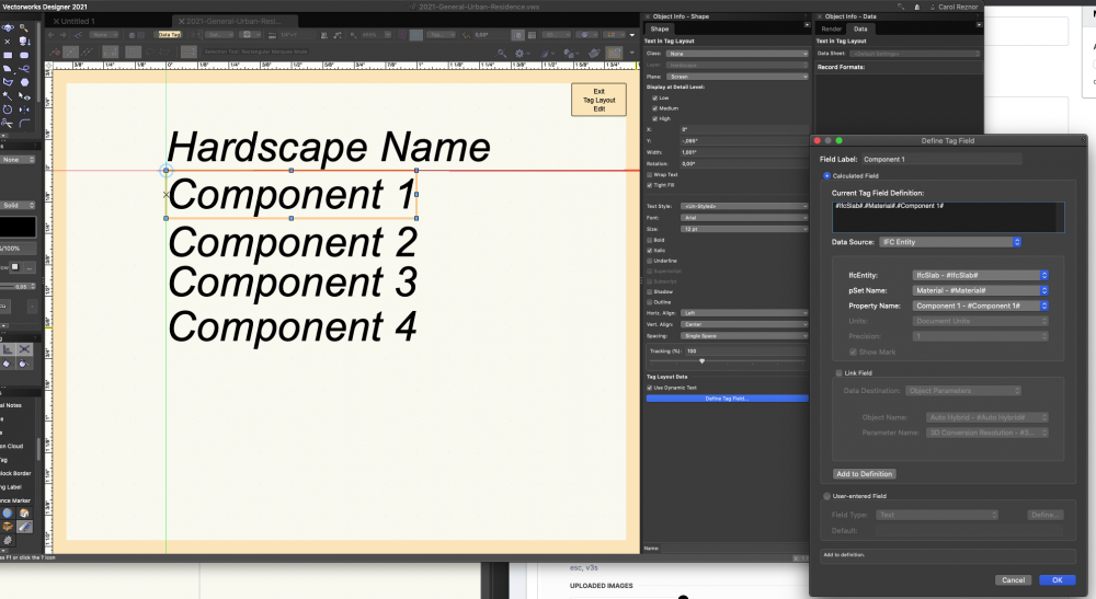
Hi For a couple of months now I have been trying off and on to create a Data Tag that can list the components of a Hardscape/Landscape Area. The use would be for instance so one can appropriately tag the components in a Section Viewport. Example below: I have been trying via Tools > Data Manager - Data Mapping of the Hardscape Object, IfcSlab > Material with the formula GETCOMPONENTINFO() Returning either the Name or the Material would be fine. (which is why I have some different selectors in the above conditions) As you can see in the OIP Data the records are greyed out... so it is doing something... Then for the Data Tag these would be the settings: Is this possible? And how...? Would be great if one could make a Data Tag for the Border Slab (and its components) too 🙂 Thanks in advance for looking into this!! Carol
-
SITE FILE COLLABORATION WITH GEOREFERENCING
Carol Reznor replied to Carol Reznor's topic in Site Design
Thanks a bunch for all the helpful feedback! If I understand correctly: say you do put the unreferenced architect file into your referenced survey. You would just 'Geolocate Rotate' - the survey so it corresponds with the building and its drawing orientation. Which makes sense - instead of first getting everything 'real world' correct and then trying to rotate everything back to the drawing angle of the architect. Right? And there is no way to rotate both the georeferenced site together with the building (as this is 'furniture') in one rotate action and keep the geolocation correct? Thanks again! -
Hi My question is in line with the topics discussed in the (WEBINAR) ENHANCE SITE FILE COLLABORATION WITH GEOREFERENCING. For example: as a landscape architect you want to make your design in your own template. You receive a dwg from the surveyor. It is geolocated. The template has the same CRS as the dwg. When importing this as a Reference into your file all goes well. Then you get a vwx file from the architect. (this file contains several layers with different scale etc and was not geolocated by the architect) You geolocate this file - same CRS as above. check it by placing a geo-image. All the layers get checked as 'Georeferenced'. You import this as a Reference into your template. Then just before you start designing you want to use the Geolocate Rotate tool so the architecture is back to '90°' to make drawing easier. The DWG rotates correctly - the vwx from the architect disappears into space... Is there something wrong with this workflow? Or could it there be something in the vwx file that messes up the geolocation of the reference? Thanks!
-
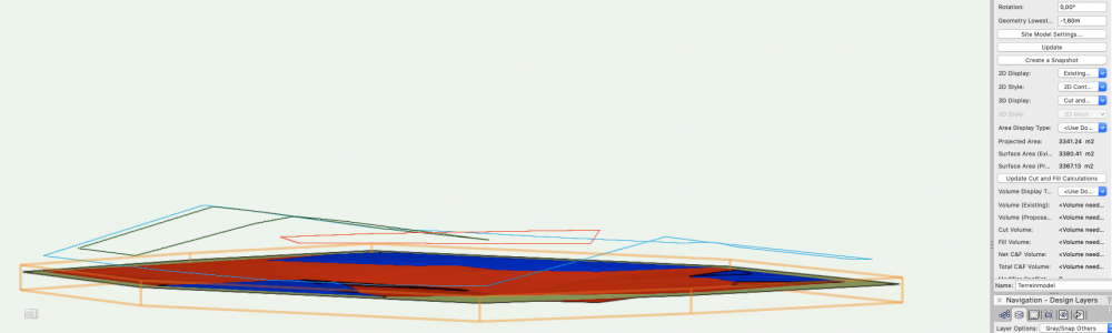
Site Model - 3D Cut an Fill Display is flat
Carol Reznor replied to Carol Reznor's topic in Site Design
Thanks Eric! The reason I was wondering is because this behaviour is not what I thought I was used to seeing... Apparently it's either my mind or my eyes playing tricks on me... or wishful thinking taking over -
Hi Last few months the 3D Display option Cut and Fill of the Site Model is acting erratic. Instead of the usual 3D model it shows a flat surface. OR am I becoming erratic? Or is there something else going on? Thanks! Carol Issue DTM.vwx