
trashcan
-
Posts
546 -
Joined
-
Last visited
Content Type
Profiles
Forums
Events
Articles
Marionette
Store
Everything posted by trashcan
-
I have viewports on two different sheets. I want to copy and paste the position of those viewports from one sheet to another. Could have sworn this could be done with the eyedropper tool! Normally, I would just copy and paste in place, but the viewports have a lot of notes that I don't want to lose. Any ideas? Obviously I can set the anchor point and copy and paste X and Y values separately, but there must be a faster way!
-
Bunch of viewports, bunch of sheets. If I update the record in an on object that only appears in one viewport, why is it that all viewports are then out of date? Is there a way to see what changed in a viewport that is forcing it to need to update it? That way I can audit things so I don't have to update all constantly.
-

Better Projector Tool Roundup
trashcan replied to trashcan's question in Wishlist - Feature and Content Requests
(just wanted to say I've been out of the loop on this thread because of a variety of things, mainly that I've been drawing this stuff manually and it works for me for now though I really really want to take the time to learn both of the tools in great detail. I love that this thread is still going and there are so many contributors!) Also @Frank Brault did any of these features make it into VWX 2022?? -
@markdd and the winner is! @Benson Shaw I didn't know you could control ambient light settings in OpenGL in the viewports. Oh! Just kidding. Lighting options in the OIP. Woof. Thanks B
-
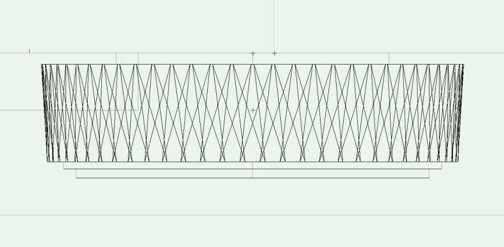
@Pat Stanfordwhat's weird about the solid section thing is that I used that same technique for the lens. So we know it works sometimes. Open GL: Wireframe: Went back to the foot where that little guy doesn't show in wireframe. Maybe it has something to do with scale? Scaling up it still doesn't show up in wireframe and it isn't clickable. Maybe it has to do with how I made the solid section? Hmmm nothing weird there. So I redid it: It worked! Weird... I also tried your sweep method and of course that worked perfectly, too: Weird, thanks for the help


-
I can't believe I'm forgetting how to do this, but how do I make a viewport black and white Open GL without putting in overrides for all my layers?
-
13 years later! This does split walls, but unfortunately turns the results into split solids, which we don't really want. Better methods?
-
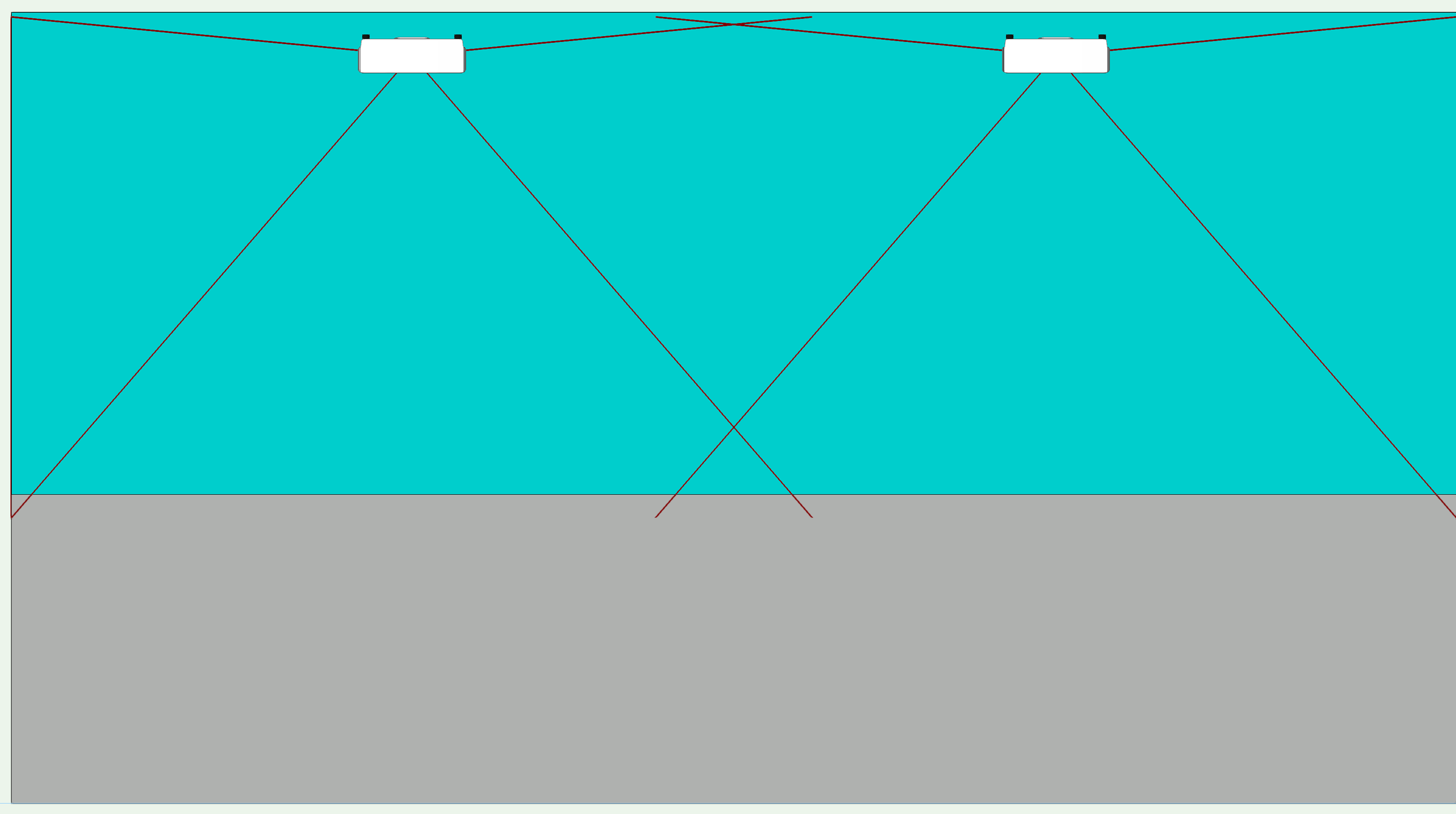
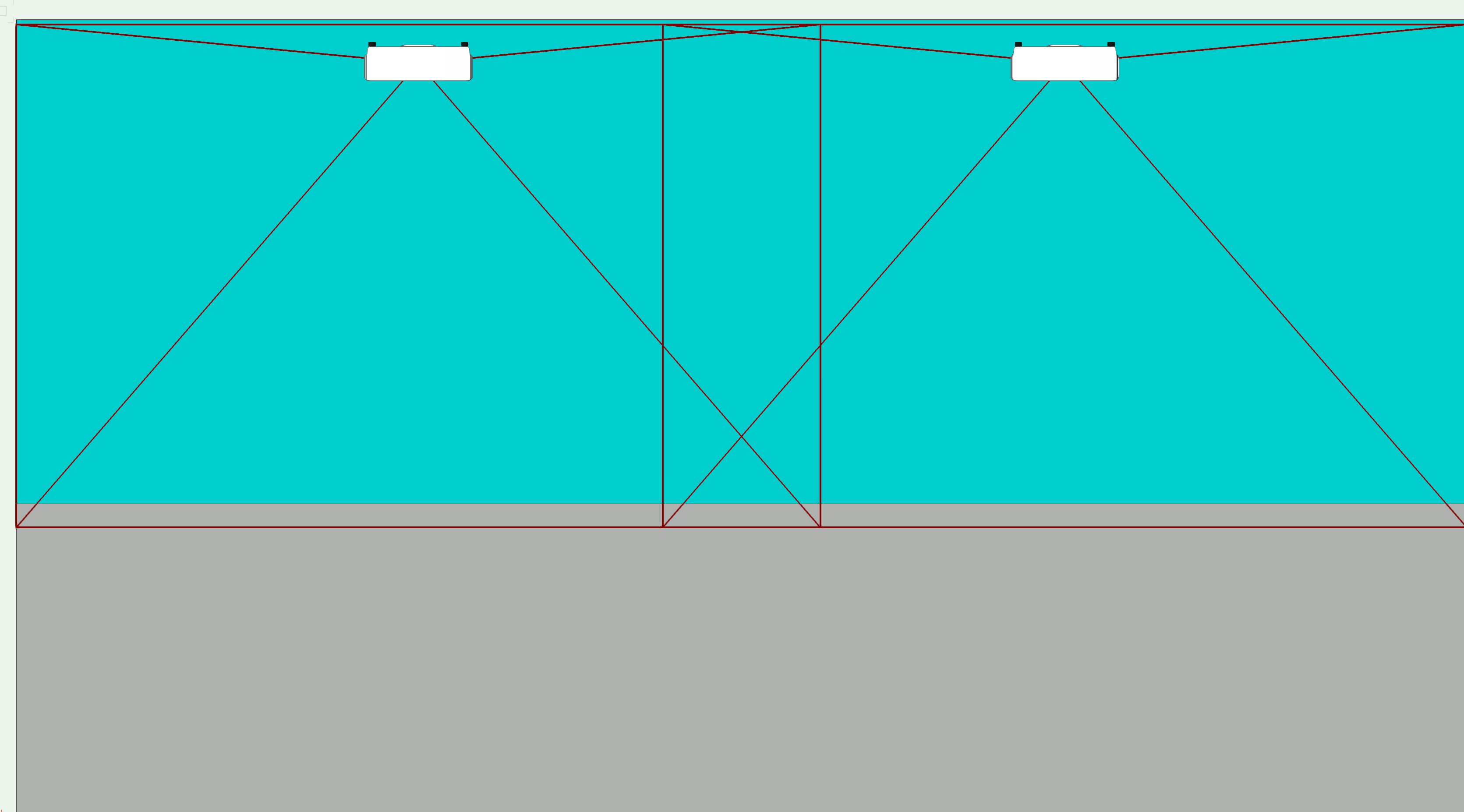
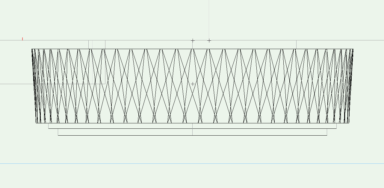
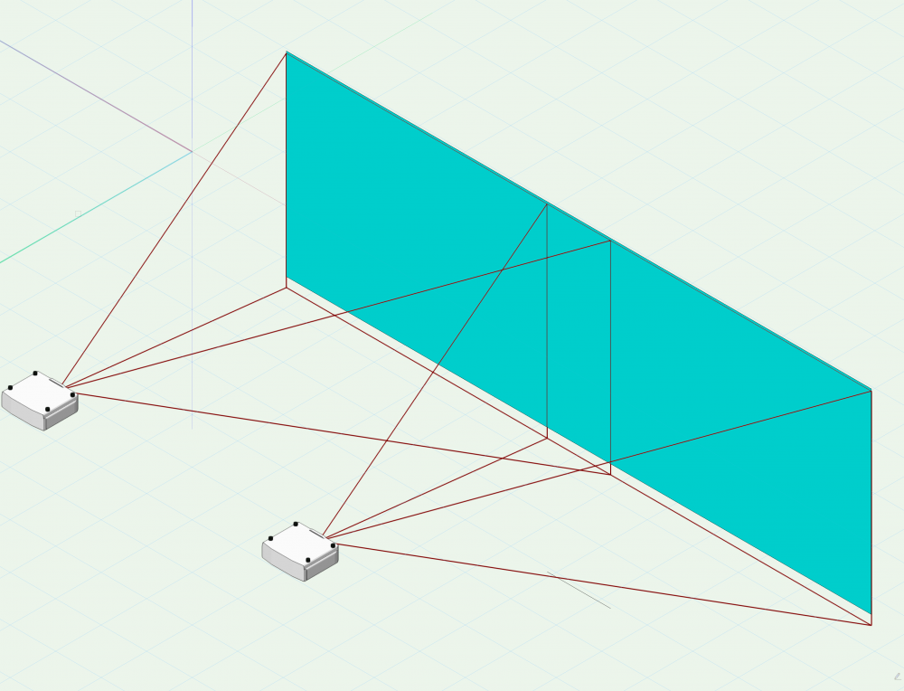
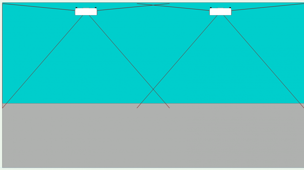
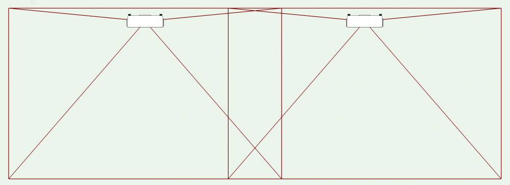
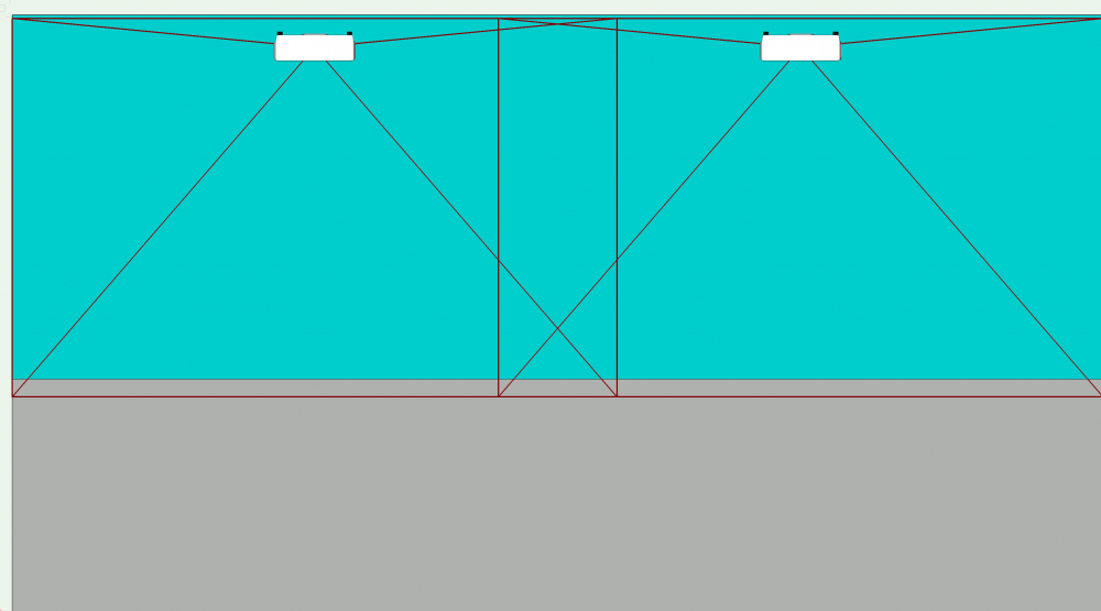
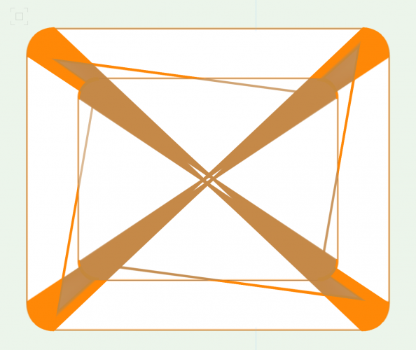
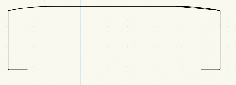
I have a work-around for this. I think it's a z-fighting issue. The work around I use I don't love because it changes the math for projector calculations and that isn't ideal. I'd love to see if there's another way to do this. For those with similar issues here's a work-around that I employ. Here's my projector study in an isometric view: Here's what it looks like straight on: Hey where'd my lines go at the top and bottom of the projection field!? Where's the blend?! It should look like this (with the target blue and grey still visible): The only way I know to fix this is to nudge the projectors back by 1/64" or the wall forward by the same. This will eliminate Z-fighting, but my math will now be off by 1/64. No sweat off my back, you say? I'm trying to keep things precise! Here's the end result, with the nudge: Any cleaner solves out there? This is confusing to me because the lines draw properly in an iso view but not straight on.
-
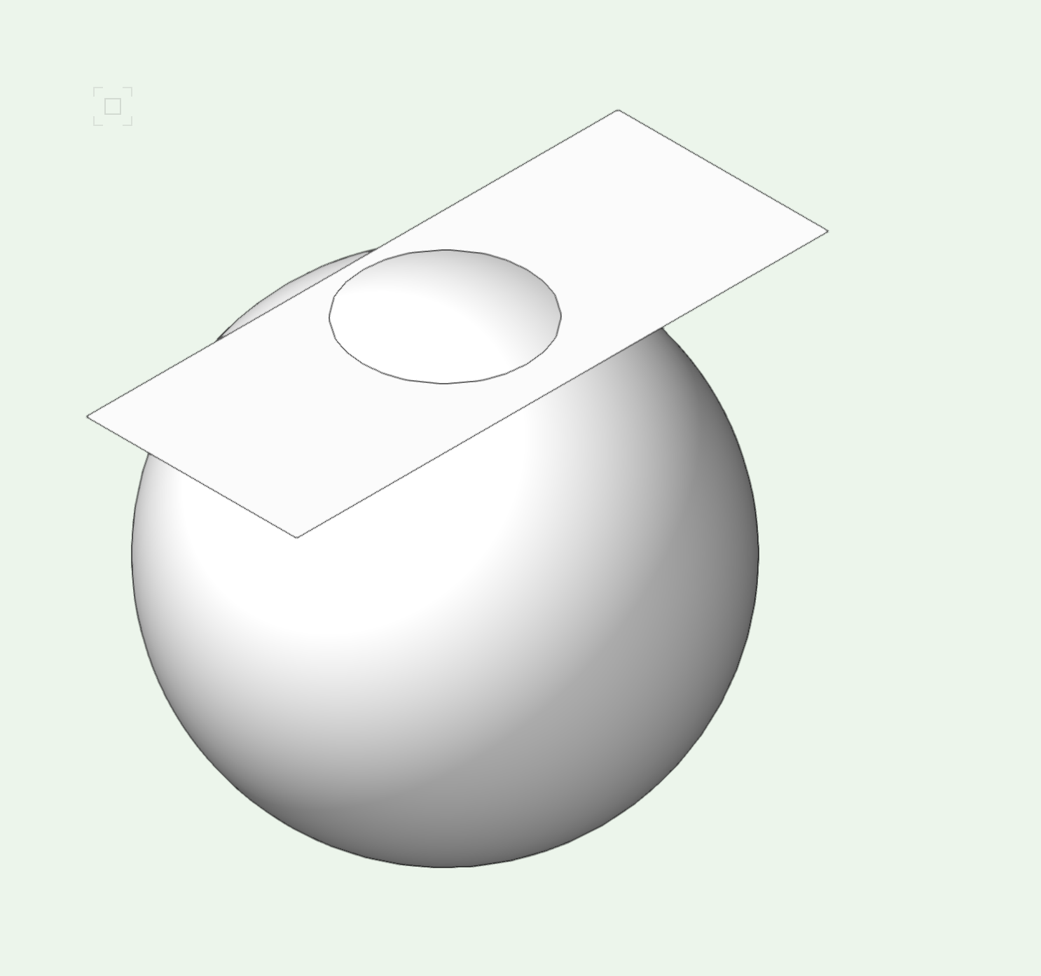
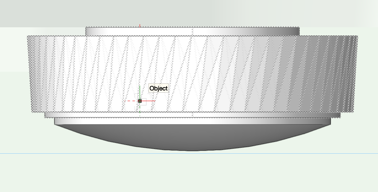
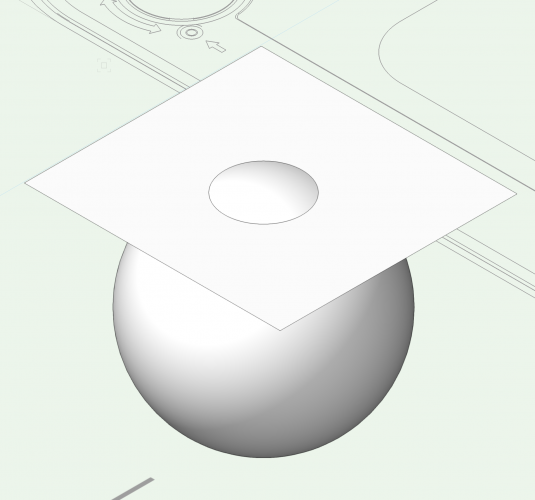
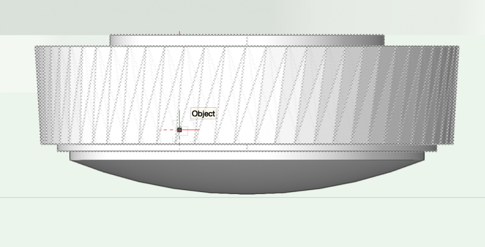
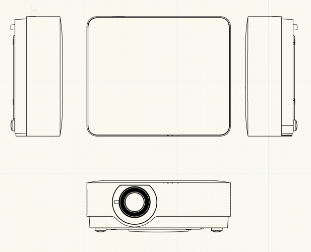
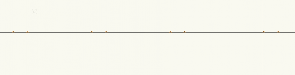
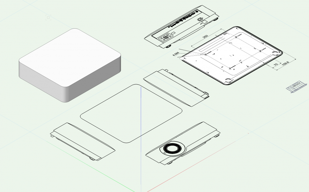
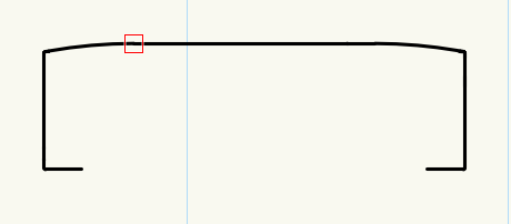
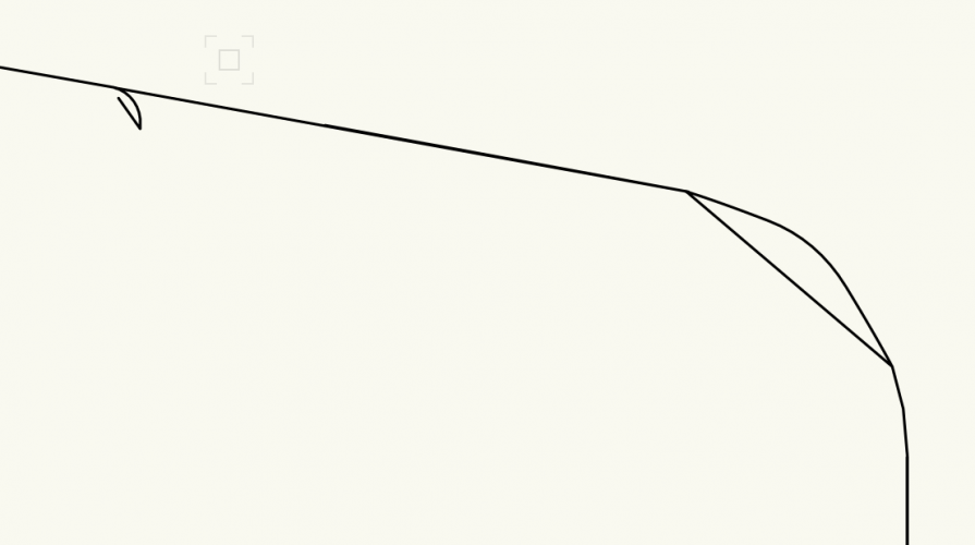
Another question. I have created the feet for the projector: To create that rounded edge at the bottom of the foot, I created a sphere and used the split tool to use only the portion of the sphere that I needed for the foot. What remained was a Solid Section. Later, I needed to snap something to the bottom of the foot and I wasn't able to get any smart points. Usually when this happens, I switch to wireframe, but oddly that rounded portion doesn't show up! I tried converting the solid section to a generic solid and a nurbs and still had the problem. Any ideas?
-
@Pat Stanford coming in hot for the win to help me figure this out. Changing the direction yielded this result: The smaller polyline object has 13 vertices. The bigger poly line has 51. Hmmm. I recreated the object that had too many vertices and it only had 13. When I did it that way, here were my results: Whatever method I used to create that bigger poly (don't remember) must be the culprit. @Art V I have not used loft solid before (or don't remember using it). Do you have any recommendations on where / how to get started?
-
I'm slowly plugging away at this model "in all my free time" And I got stuck: I have two shapes that I need to do a multiple extrude with a depth of .291" It gets super nasty if I do a multiple extrude: If I just the bigger rectangle and do a flat extrude at .291", and then use Deform-->Taper Solid, I get close to what I want but not exactly right: Close enough for jazz! But how do I do it right, I wonder?

-
@Art V yeah, you'd think you could do that in VWX...
-
@Boh tracing is a little tough for me to be honest. I come from Creative Cloud world where line tools and bezier and polygons are a bit more intuitive and I've found it very difficult to adapt to the VWX Polyline tool (especially dealing with curves). But that's a great suggestion! @bcd that's also a good call!
-
I've done this a few times now and I'm looking for best practices / a faster solve. I got this DXF from the manufacturer: I then go through and delete all the junk I don't care about: I then do that in a fine tuned way trying to delete all the artifact junk from the DXF: Then I pick a surface as my base extrude and use the command "Combine Into Surface" and extrude it to the depth that I want: Then I rinse and repeat for all the other blocks and then combine at the end. Is there a faster / smarter way to do this?
-
Deep thread but more questions. I have a ton of poly-lines that I want to connect. It's dozens of lines and I want to think about best practices. I'm trying to create a shape from a DXF so I can extrude it. Not all the end points are connected end-to-end (there are some gaps). Compose results with: There are now fewer line segments so I could use connect / combine from here, but it's still slow going. And I have all this noise to contend with: What's the best way to do this?
-
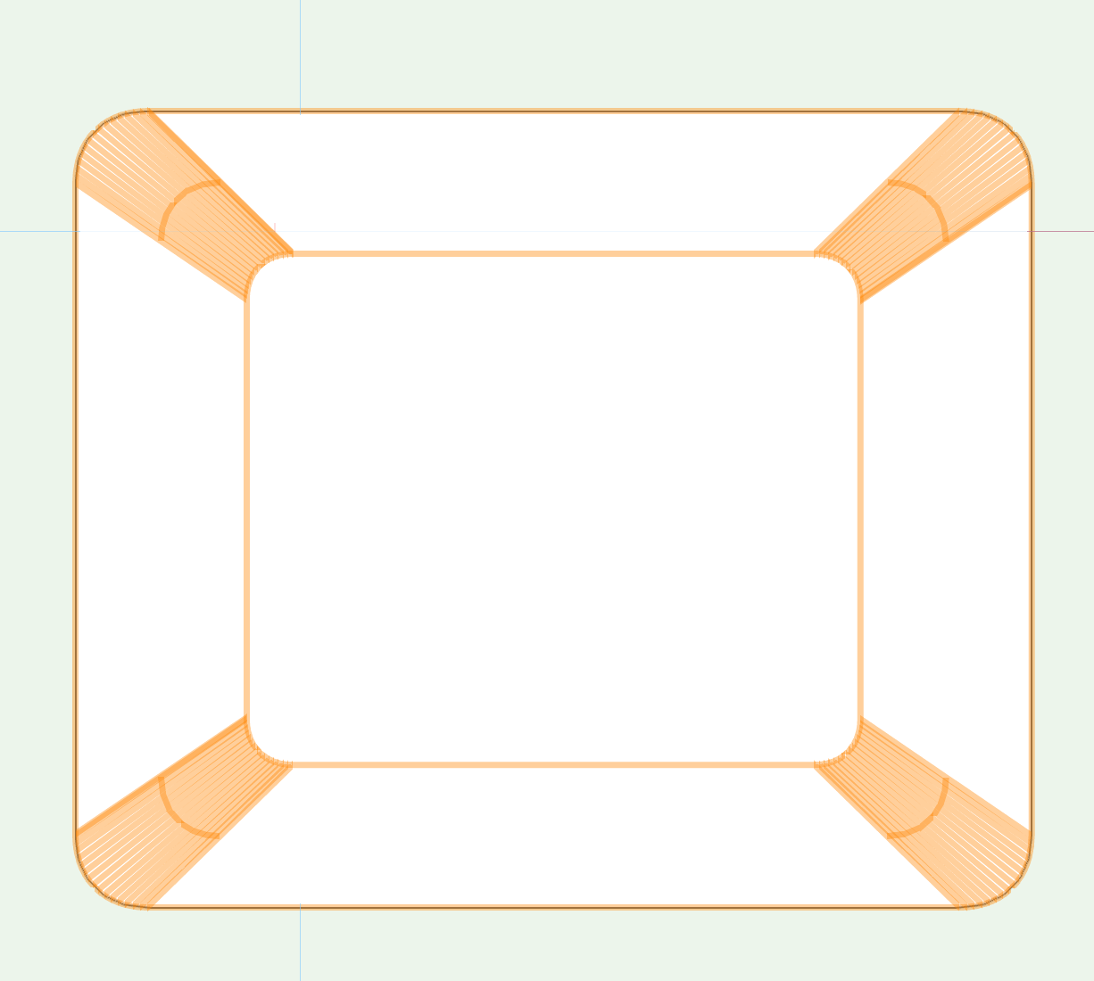
PS an unfortunate side effect of adding an extra crop as the work-around is that aligning those viewports now aligns with the crop. Seems just like an OpenGL bug that need to be repaired...
-
Perfect, thanks @michaelk
-
So I have some additional non-viewport images on my Sheet Layer. I've put a Drawing Label with each of them and assigned a number. I've then grouped them. However, when I create a standard Viewport with a Drawing Label, it doesn't see the numbers I've used for my "manual" images. Is there a better practice than this? I could, of course, put the images in my design layer, class them appropriately and then use standard viewports but that seems like a whole lot of unnecessary work. Ideas?
-
👋 @Pat Stanford The work around I used was to create the slab using the inner boundary. Then, edit the boundary and use the offset tool with the wall thickness set as fixed offset amount. Done!
-
Tip: Import vector graphics in 2019
trashcan replied to Kaare Baekgaard's topic in General Discussion
Can confirm this works! -
It seems to me that you should be able to set the Slab creation to Outer Boundary (when creating walls) but can't find it. Is it possible?
-
Absolute Height Option for Wall Components
trashcan replied to Tom Klaber's question in Wishlist - Feature and Content Requests
Was trying to figure this out and it pointed in the right direction. I want to create a wall with Wainscot that goes 2' from the bottom of the wall. Here's the trick that worked for me: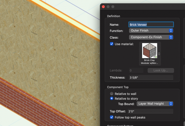
-
@michaelkcorrect! I was creating it on a sheet layer so the options weren't there for plane. I moved it over to a design layer, changed all the objects to screen plane and the rest is history.
-
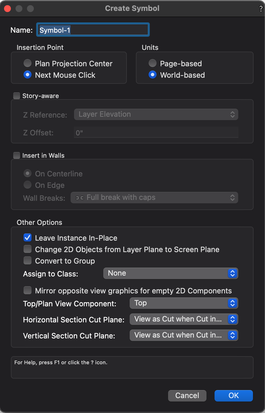
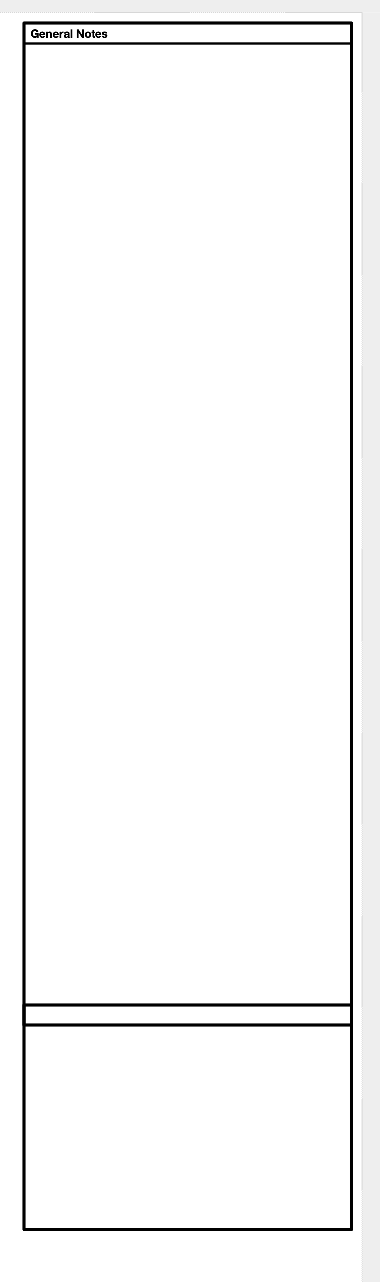
I have a custom text block that I use for notes and I'd love to make it a symbol. When I make it a symbol, all the text fields disappear: What am I doing wrong here? (I may link these text areas to individual records so that I can customize text later, but for now I just want this whole thing as a symbol in my RM so I can reuse it as necessary). Maybe a symbol isn't exactly what I want? I just want to be able to reuse this element freely and want to make it more streamlined than copy and pasting from my template document.
-
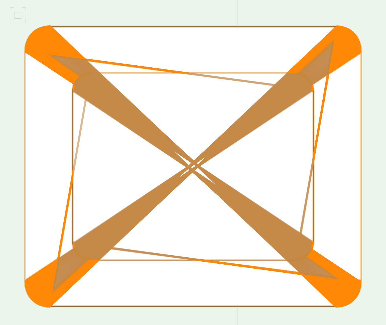
@Dave DonleyI do not have any crop on any of these viewports. The work around here is to ADD a crop that is bigger than your viewport. Then the lines appear. It would seem to me that the auto viewport (no crop) should take this into account and draw all the lines within a viewport (including edge pixels). Dave can you separate this post between Tobias' request (which I agree with!) and the actual bug I've reported here? I don't know why they are both in this post!