


Conrad Preen
-
Posts
1,027 -
Joined
-
Last visited
Content Type
Profiles
Forums
Events
Articles
Marionette
Store
Posts posted by Conrad Preen
-
-
-
Hi @DSchoepke
That sounds interesting and on the verge of being totally possible! Nested rooms are something we are looking into. You can add user fields to ConnectCAD objects and visualise them on the drawing (see this thread)
If you are not in a big hurry even better ways of doing this are coming 🙂 .
The locations of physical equipment (as opposed to theoretical schematic devices) are defined by Equipment Item objects. When you move this object around it detects its location in rooms and racks and updates the corresponding device(s). All that happens automatically. The location information appears in the default circuit report too. So you can filter by this also. You can assign your own symbols to Equipment Items in the Object Info palette to have whatever look you desire.
ConnectCAD reports are normal Vectorworks reports - no magic. We just have them in the menu to make life easier. You can customise them to add extra fields, modify the criteria to filter by location etc. etc. and you can save it all as a template so you only have to set this up once.
If you have time to PM me some example files I'd really like to see what you are doing and maybe I can offer more specific advice.
Regards
Conrad
-
 1
1
-
-
@stancilent If you could PM the file, I can look into why the Get Connectors button isn't working in your case.
Thanks
Conrad
-
@stancilent Please see my reply to your other post on this subject. I think you are using the wrong kind of device for this purpose. A Term Panel would make your life a lot easier.
Conrad
-
Hello @stancilent Doesn't it also "suck" when the text is too small to be readable? Anyway, you can set the text size by selecting the object and using the Font menu to adjust to your needs.
I am curious as to why some people choose to model standard rack-mounting panels in this way using CTPs. The Term Panel tool is designed to create these kind of devices. And when you create the equipment, you can set any Equipment Item to use a symbol for its graphics using the Object Info Palette Display > Use Symbol option. That gives you the way to visualise the connectors in as much detail as you like.
Connector Panels were actually intended to help design those myriad custom connector panels that appear all around venues. For standard rack-mount panels they are an over-complication IMHO.
Be interested to hear why you are doing it this way.
Conrad
-
Hi Thomas
You can do what you want in ConnectCAD. You can have multiple instances of the same device (i.e. same name) and if you have also duplicate sockets across those devices it's OK. ConnectCAD will simply carry on working. Circuits will collect the data from the sockets and devices at their endpoints and this data will appear in reports. If those reports contain conflicting info (e.g. 2 cables going into one socket) that will be because you designed it that way.
But you can't have your cake and eat it. Meaning that you can't expect Check Drawing to "know" that in some cases sockets are intentionally duplicated and in others not. I don't think it's a good idea to add exceptions to the rules that Check Drawing uses. It only creates ways for things to go wrong.Nothing in ConnectCAD stands in your way as far as I can see. You could probably hide your duplicate sockets using classes to help you avoid unintentional connections. When you have finalised your design just delete the unused sockets and Check Drawing will make sure you have no issues remaining.
Best
Conrad
-
Hi @Ross McLee
I thought the Check Drawing command did that. Could you please PM me the file in question?
Conrad
-
Hi Thomas
My 2c worth...
I would not use the class system to control whether a socket is enabled for connection or not. Classes get turned on and off for all kinds of reasons.
In 20 years you are the first to express the thought that duplicate sockets in duplicate devices might be allowed if we could somehow mark those sockets as disabled. Others may have thought it but they didn't say. It will take a few more votes to persuade me that the current way is wrong. Seems to me we should look at why it feels hard to reconfigure a bunch of sockets in a device.
Getting Check Drawing to ignore intentionally duplicated devices while detected accidental duplicates - that could be interesting. So the question in my mind is what if that intention goes away in a subsequent iteration of the design? Suppose we did somehow mark a duplicate as being intentional then how would it get unmarked?
We will think about it. Not promising anything. I still like that fact that Check Drawing has no state. Like justice it is blind.
Cornad
-
Hi @teedd
I have the feeling that this may be a case of mixed service packs 2021SP2 and SP3. If one of you upgraded and the other did not then saving back to SP2 can cause this kind of thing. Is that the case here?
Thanks for sending us all the files by the way - this really speeds up diagnosis. We investigate and get back to you.
Conrad
-
Dear @Thomas_
First of all, you are not limited to the devices we provide. You can easily create your own and you can edit the standard devices to create what you want. What you describe with a pass-thru connector is a term panel where you have a cable connector on both sides. Check out how these are configured and maybe that will be a solution for you?
Conrad
-
Also you can set the Text Align parameter to Above.
Thanks for sending the images of how you are using custom panels. Originally I had not envisaged these being used to depict standard rack mount panels. When I was a designer they never gave me enough time to draw these things in that level of detail. Now that I see what you are doing I will keep that in mind and see how we can accomodate this better.
Thanks
Conrad
-
Just to add a note here. ConnectCAD allows you to have two devices with the same name on your schematic BUT, it thinks you are talking about the same device. If these two devices have two sockets with the same name ('cos you duplicated the for example) then that's registered as an error. Why? well think how confusing the cable list will be when the installer sees the same device and socket names with two cables going to the same connector!
ConnectCAD isn't a policeman. And you can break the rules if you like - just remember to fix the naming before you go.
Regarding performance interesting to see if we can reproduce that.
Conrad
-
Thanks for your input!
-
Hi @Thomas_
The mostly likely reason for the "not working" thing is snaps. If your sockets are off the grid and you have snap-to-grid on only then the tools miss the point. You can enable snap-to-object or align to grid using Cmd- (command or ctrl and the minus sign key) or the Align to Grid menu command.
CTP connectors are a bit special because they chassis connectors. Everywhere else in ConnectCAD we only talk about the cable connector. So a chassis connector can be of two types plug or socket. The sockets have the special X orientation which allows them to accept an incoming connection on the left and source an outgoing connection to the right. So on a schematic one side of the socket has bare wire ends on the cable ( going to the back of the chassis connector) and the other has a normal cable connector. We use the types IN and OUT to distinguish these.
That's the thinking.
Hope I've helped.
Conrad
-
Hi @Wade
Yes Plug-ins\ConnectCAD_Data is still the place where the signal and connector types go. I am a bit puzzled by what you're seeing but I have nothing to go on yet. Could you PM me the file that has the disappearing names? and also the Signal and Connector types files that you want to add? Could be something to do with the format of those.
Conrad
-
1
-
-
Hi Ean,
Yes I'm seeing that and I'm filing a bug. Thanks for letting me know.
Conrad
-
Hi @Ross McLee
I checked the file. I think these arose because you renamed the device the circuits were connected to. When I select one of these circuits the source and destination device is Loudspeaker. So I suspect that you created these by accident during a duplicate-modify operation. You can tidy these using Custom Selection.
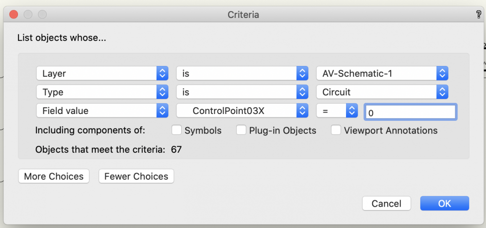
We'll select for Circuit.ControlPoint03X = 0 and just delete them.
Best
Conrad
-
1
-
 1
1
-
-
Hi Ross,
If you see this again could you save the drawing and PM it to me? It might be something we should look into.
Thanks
Conrad
-
Hi Nick,
Just to be clear. You need to start from a blank document (not the template). Import your .dwg. Set up the snap grid. Leave Unified View on. If you want your schematic on a separate layer from your floorplan create that layer at the same scale (1:50 right?).
Now start using ConnectCAD tools.
As you add devices / sockets etc. everything you need gets imported and scaled to match your snap grid setting.
Note: changing the snap grid will not affect objects already on the drawing or anything containing symbols already imported and scaled. You need to set the snap grid at the beginning and leave it there.
Any questions just let me know.
Conrad
-
1
-
-
Hi Kevin
Busy time of the year. This has a Marionette feel to it if I'm not wrong. You want to have a grid view of a connectivity drawing- correct? Be even cooler to do the interface to the hardware and join that to Vectorworks.
Conrad
-
Hi Nick
You can draw your schematics on the floor plan. Event planners like to do this because they can read the cable lengths directly from the perimeters of the circuits. It's quick and dirty.
What you need to do is set the snap grid to a suitable value. The snap grid controls the size of all schematic objects. If your floor plan is at 1:50 grid sizes of 125mm or 6in will look nice. But you'll have to see what works for you. Set up the grid, import your DWG, then start using ConnectCAD. Symbols are automatically imported from default content as required and scaled to your grid. So don't go changing the grid halfway through!
Hope that helps and I'd really be interested to see how this looks.
Conrad
-
Hi @Ben59
Let me chime in here. I think you are jumping to conclusions. ConnectCAD is perfectly suitable for designing systems inside and outside racks. Many people use it every day for these purposes.
Equipment items on floor plans and in racks are different from devices on schematics. If they were the same we would use the same object! An equipment item is the physical device. A schematic device is a container for some or all of the connectors available on a particular type of equipment. There may be more than one device on a schematic associated with the same physical equipment. For example, an audio-follow-video mixer would appear on the audio schematic AND on the video. Patch panels are divided into multiple devices so that you can place them into circuits. That way your schematic will illustrate the signal flow - its primary purpose.
What this means in practice is that we cannot easily automate the creation of devices from equipment - because we do not know what is the configuration of those devices. Going from a schematic to physical equipment on the other hand is easy because each unique device name is one piece of equipment. In fact the name is the only thing we absolutely need to know in this case. The size, power and weight can be set later if need be.
But let's look at how we could implement what you want for a moment. We have two cases:
1. the type of equipment / device is recorded in the Device Builder database - then we would create a device with all available sockets for that type
2. the type of equipment / device is a standard type e.g. patch panel, term panel, distribution amp etc. - then we create a standard device
3. the type of equipment / device is unknown to our database - then we create a blank device and you add sockets etc.
All sounds great until you look at the details. By the time you've sorted out this mess of devices placed around the edges of your drawing, configured the blank devices, removed irrelevant sockets from Device Builder devices, you are probably looking at the same amount of work as creating the schematic from scratch.
The bottom line is that there is always some work involved.
I don't want to sound negative. We the ConnectCAD team are committed to working to make designers' lives easier. And these discussions are part of the way we move forward. I'm ready to work to support any workflow as soon as I can see a way through.
Thank you very much for sharing these thoughts. Vectorworks 2022 will have many features that you will find interesting! I'm looking forward to working with you to make it even better.
Kind regards
Conrad Preen - Product Planner ConnectCAD
-
@tk_ Agree. The forum search engine leaves much to be desired IMO. If you search topics then you have a chance. Inside threads it becomes unreasonable. I would encourage everyone to create a topic unless you are absolutely sure. When we attach these to bug reports it's way easier if it's a short thread. I'm certainly not criticising, just trying to make the best of what we have.
Just FYI and for all the others out there.
Conrad
-
1
-
-
@tk_ Just a note. New topics cost nothing 🙂 and they don't allow me to move stuff for you.. So to avoid having your question buried in the noise here.... please create A NEW TOPIC 🙂
Conrad
-
1
-


Did Vectorworks ever add the option to change text size and style inside rack item?
in ConnectCAD
Posted
I think you have to understand that software like living organisms evolves. Evolution isn't perfect either. The Vagus nerve is a great example. It goes from the brain down the neck around the aorta an back up to your throat. Nuts! Except of course back when our distant ancestors were fish that was the most direct route...
So back to software. The problems we are trying to solve change over time and our expectations of software increase exponentially. In a way yes, panels are panels. I've certainly thought about merging them. But putting everything into one tool with a zillion modes won't necessarily be easier to use.
In the end a design is a model that has to be good enough for an installer to execute. It doesn't have to be absolutely perfect. I've found in my life as a designer that the more I removed the need for the installers to think, the less they engaged their brains and the more frequently they made stupid mistakes. So I started to do the opposite. Give them less information so they were actually forced to think. Performance and accuracy improved as a result. Just my 2c worth.
Conrad