


BSeigel
-
Posts
118 -
Joined
-
Last visited
Content Type
Profiles
Forums
Events
Articles
Marionette
Store
Posts posted by BSeigel
-
-
You are very welcome,
"Did you create this "Source-4 w/SideArm" symbol?"
I did create a symbol for the sidearm/clamp that I nested in the symbol for the Source 4
"The actual SideArm is NOT an accessory, but will create a different count of fixtures?"
The sidearm is inserted as an an accessory, clamps can be set as accessories in 2021. For counting fixtures I would recommend using a worksheet that summarizes fixtures based on instrument type.
"Those with C-Clamps and those with SideArms?"
The clamp came from the VWX libraries, I think I modeled the rest. Should be easy enough to customize.
"Do you need one for each degree-type?"
I would recommend creating a symbol for each clamp/fixture combinationHope this helps!
-
 1
1
-
-
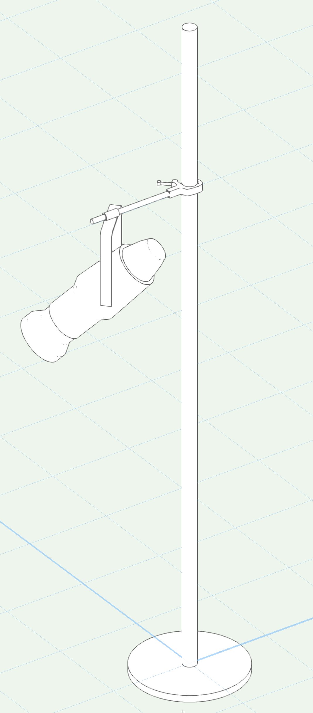
I browsed through the thread and came up with a quick mockup. Is this close to what everybody is looking to create?
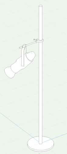
Side Arm.vwx-
2
-
-
Sounds like fun! Let me know how it goes
-
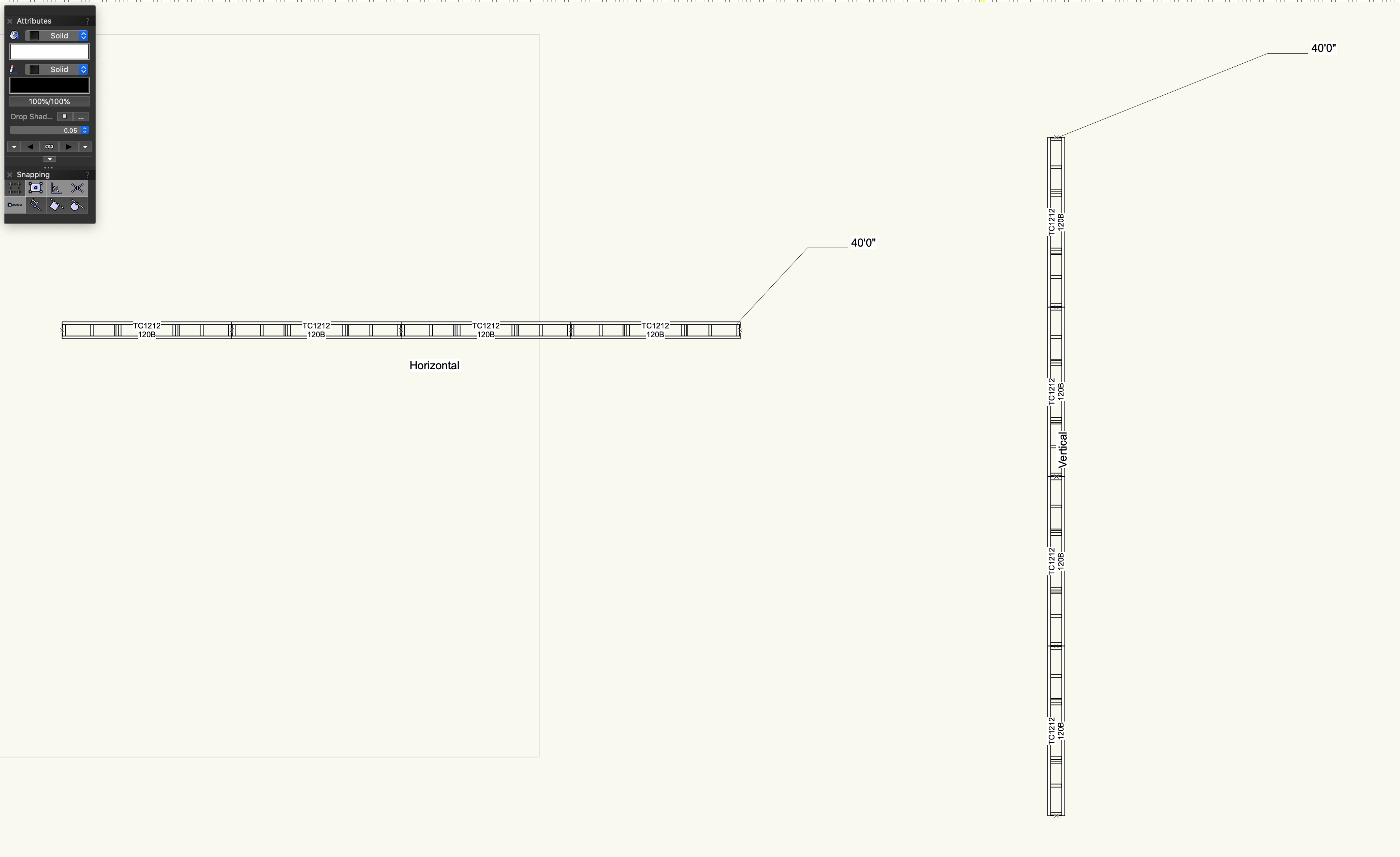
Not the most elegant solution, but you can pull this off with a hanging position and an object function. The catch is it wont do much for angled truss and I don't feel like doing any trigonometry. File attached for reference.
-
Rather than modifying the truss symbols. I would suggest creating duplicate versions (like a HUD version) of your lighting symbols that have adjusted insertion points in the 3D component. This will only be an issue if you are going to export to a visualizer like Vision. Personally, I'd rather have that issue than lose autoconnect functionality.
Ultimately, the proper way to handle this efficiently would be to use the Align and Distribute tool in 3D. -
For sure, feel free to send over the file if you cant get it working and I can look it over
-
1
-
-
To eliminate some variables, I would also recommend testing on a design layer without using a RW camera. (using a normal perspective is still encouraged) Once you get it to work, start working with viewports
-
This attached pdf might help. Check over the settings in the document and let me know how it goes.
-
1
-
-
If you are using focus points for the lighting devices, you can have this happen automatically by changing a setting in the Spotlight Preferences.
-
1
-
-
Would you mind sharing the file?
-
It's a bit of a cheap rendering trick but you can always use the extract tool to pull a NURBS Surface from one of the faces. Then you can independently control the texture on just that surface. You may have to adjust the position of the NURBS surface slightly to avoid Z-Fighting. But everything should come out fine in renderings.
-
First, make sure the truss is centered directly beneath the house rigging point to ensure the greatest chance of success. Next, insert a single drop, this should attach the house rigging point to the truss. Now select the drop, go into the Object Info Palette and choose the option to replace the down leg with hoist. Let me know if you run into any issues.
-
For sure, I simply do not know what you do not know and over-explanantion is the safer way to train. Especially for any user that discovers this forum post in the future.
You are correct, there is something strange going on in those images and it appears to be specific to 2019. I still want to test it some more before submitting the bug later this afternoon. For now, working in 2020 should alleviate some frustration from this workflow. -
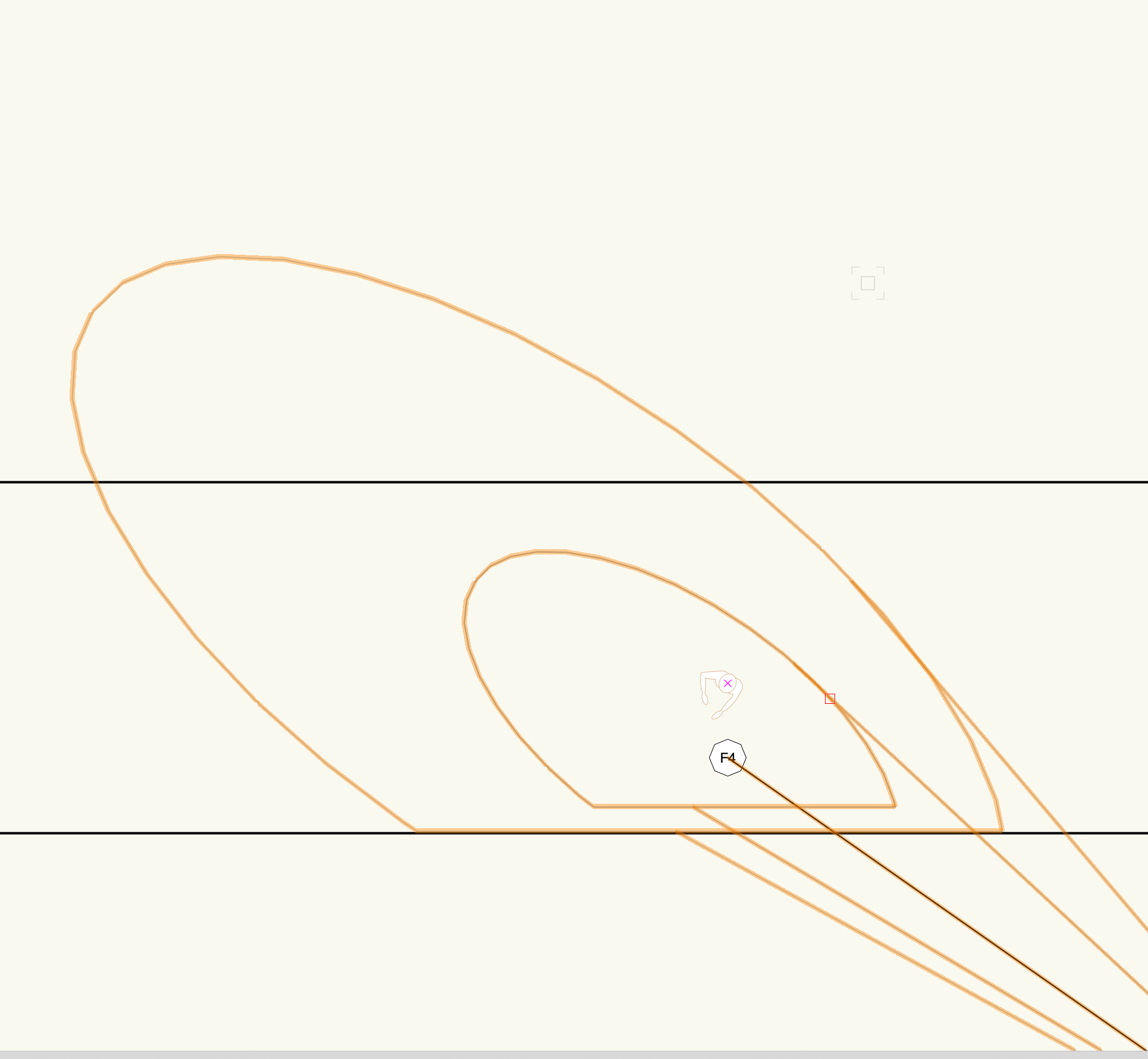
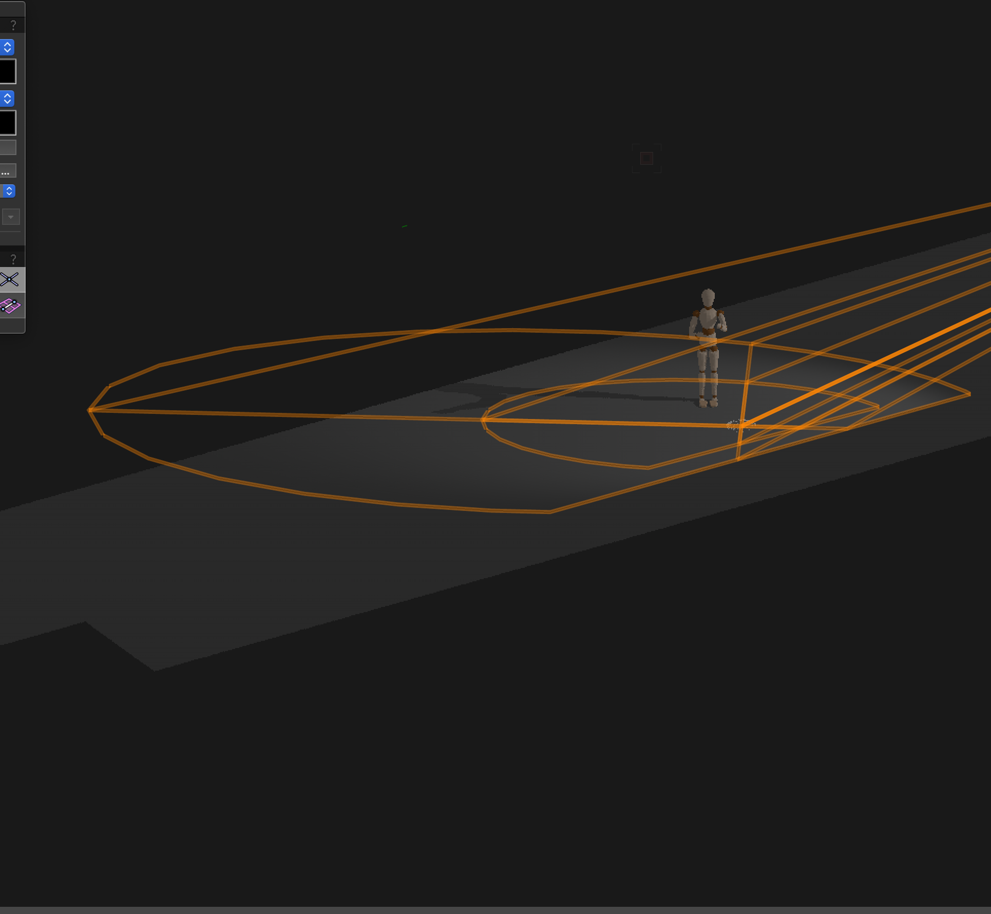
Good news: nothing seems terribly broken, but this can be a confusing workflow. This picture illustrates what is happening:
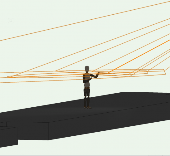
In Top/Plan it would appear as though draw beam is showing the shutter cuts relative to the stage. But it is actually showing how the shutter cuts would play out on an imaginary plane 5' above the stage deck. Where the shadows from the shutters land on this imaginary plane will not be consistent with where the shadows from the shutters would land on stage. Light traveling, trigonometry, and all that good stuff...
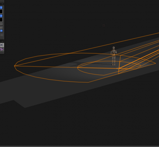
From here you can go one of two directions, I'll start with what I recommend. Take all of your focus points and put them at the same elevation as the top of the stage. Now, draw beam will match up much more closely to how the light will land on stage in rendering. I know this isn't proper given the height of the hot spot, but it will make life much easier and you can still move them up and make final adjustments later. I will say in 2019 I did occasionally have some strange results from shutter cuts using RW but it was significantly more accurate in 2020.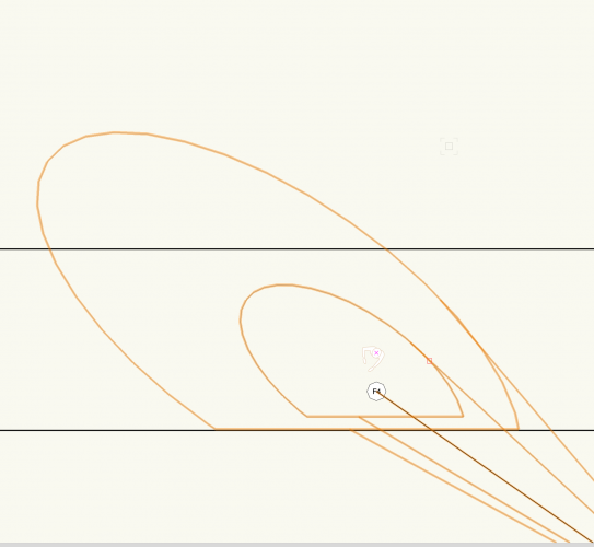
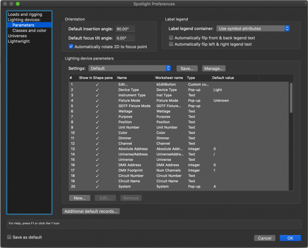
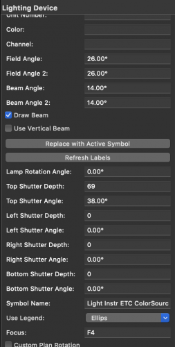
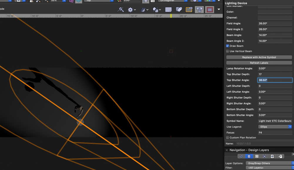
Option 2 is to leave the focus point where it is at and dial things in from a Top view using Fast RW. One thing I noticed about your file was that you didn't have any shutter cut info in your Object Info Palette. This leads me to believe your were going to the edit lighting device dialogue every time you needed to make a change. You can save a lot of time by going to File>Document Settings>Spotlight Preferences and locating Lighting Device Parameters. From the list set the "Show in Shape Pane" check mark for all the shutter fields. You can now make these changes for multiple fixtures in the OIP.
Again hope this helps. Like I said earlier there is certainly something weird in 2019 and I will look into that further.
-
Are you able to share the file that you pasted objects into?
-
Does the issue persist if you bring the lights, focus points, and stage into a separate VWX file?
-
That does sound strange, are you able to share the file?
-
What is the DMX Provider set to in Vision?
-
Floor objects and even Roof Faces can be useful for drawing a stage as well
-
Are beam and field angle enabled in the spotlight preferences? Are beam and field angle assigned to any classes?
-
What height are your focus points at? Having them just above deck height will make it easier to see what the shutters are doing in draw beam. Hope this helps
-
@JLitterio Would you be able to share the file so I can take a look at it?
-
@DukeC and @hbeach This seems to be the current behavior in both 2019 and 2020 and is technically working as designed. I agree that it would be better to have the ability to choose if the label displays in 3D as well so I have submitted a enhancement request: VE-100274
@Larry Cook If you bring in anything besides the first 4 options in the dropdown, it should automatically import a symbol into your Resource Manager with the same name as the option you selected. First, check that all of your classes are visible as this is the most likely issue. Second, try and locate the symbol in your RM and check the 2D/3D components. Third (stretching here), if there was another resource with the same name there could have been a resource conflict that caused the symbol to not import properly. -
The 2019 library files will not appear in 2020 because they need to be converted to 2020 files.
1. Open Vectorworks 2020
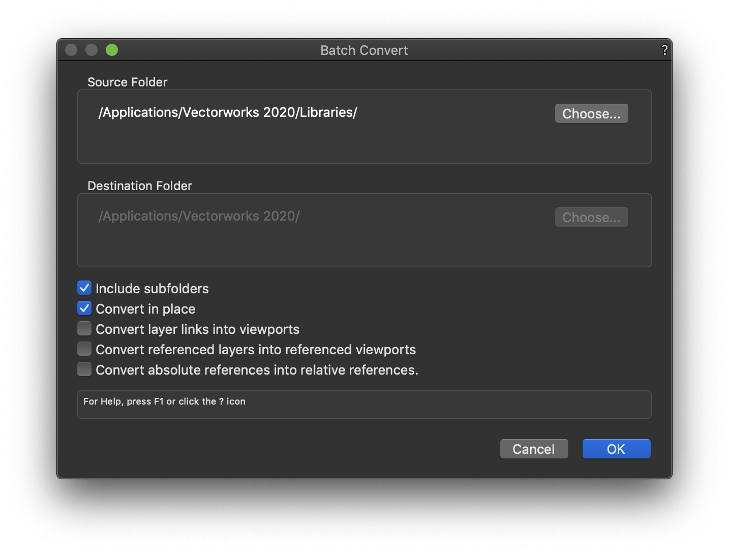
2. Go to File>Batch Convert
3. Use these settings (This is assuming that you have already moved the 2019 files into your 2020 Library folder)
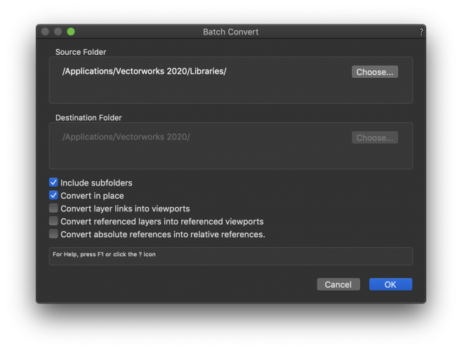
4. Choose OK. Depending on the number of files, this can take quite some time, so take that into consideration. Once it has finished, 2020 should recognize all of your library files
-
1
-


Hoist Tool 2021 & Up Proper Weight Field & Format
in Entertainment
Posted
Hello @MattG I actually ended up putting something together along these lines a few weeks back. The proper answer is to use Braceworks and have it fill out all of these fields for you. However, not everyone has Braceworks and it would be nice to punch in some information and have it add up in the correct hoist parameter. While it's not an official workflow and you should take all necessary precautions, using a mix of Data Tags and the Data Manager, this is possible in Spotlight. I had a user request to automatically calculate total point load, which is past VW terminology for Hook Weight Equivalent. The formulas are pretty basic except that a lot of the non-formatted fields are in grams and require some conversion. I don't have much time today so I'll post the file for now and try to upload a video soon.
Point Load Data Tag with automatic Hook Weight Equivalent.vwx