


Daniel Dickman
-
Posts
101 -
Joined
-
Last visited
Content Type
Profiles
Forums
Events
Articles
Marionette
Store
Posts posted by Daniel Dickman
-
-
7 hours ago, Conrad Preen said:
I'm just wondering if I make the popup go from 1 thru 512 if that will sort out the problem for you. It's only the start of the number series - if you begin at 256 the devices get numbered 256, 257, 258 etc.
Conrad, is there any reason the start number couldn't be input by the user into a text field as opposed to a dropdown with limited options?
-
16 hours ago, TomWhiteLight said:
I think you can attach the truss record to the symbol. I think...
Hmm I was able to attach the truss record but when i try to create a schematic view it still says the object must be a rigging object.
-
It seems that when using the ConnectCad "Renumber Devices" function, your staring number can't be higher than 256. You could always select all of the devices and then renumber starting at 1. I just tested this and it worked with 600 devices.
Another option, which in my opinion gives the user much more flexibility is to use the Spotlight numbering tool. Check out this post for a tutorial.
-
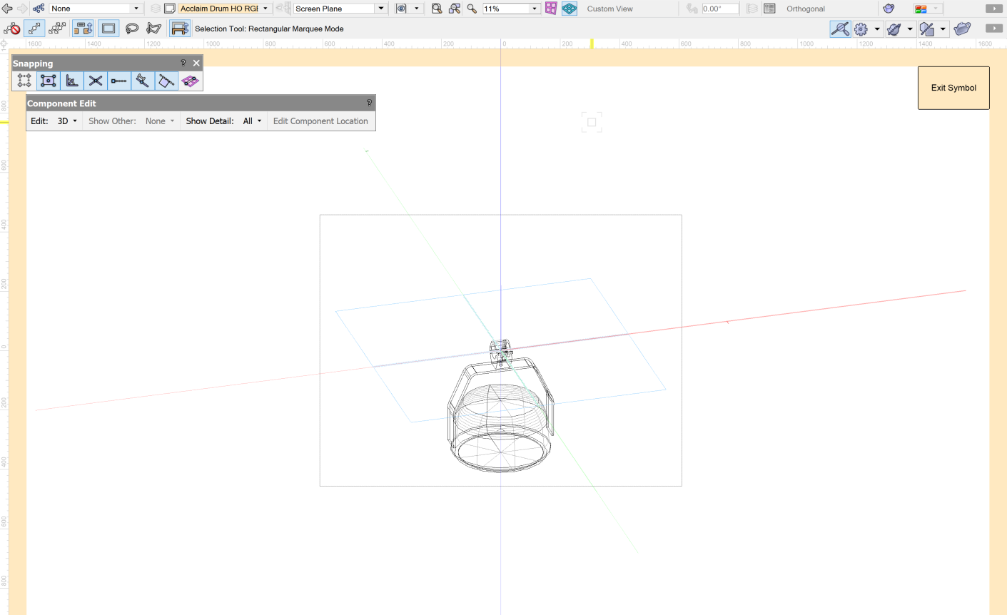
Since schematic views do not like hanging positions and schematic views require rigging objects... How do you turn custom 3D geometry into rigging objects?
I have a 3D symbol for a custom ladder but see no functions in Spotlights to turn this into a "rigging object"..... besides the convert to hang position function.
-
Along the lines of editing 3D symbols... When editing the 3D component of a hybrid symbol, I've recently noticed that I can not select a 3D view from the drop down. Flyover works fine but the 3D view drop down is grayed out. Any ideas? What am I missing here?

-
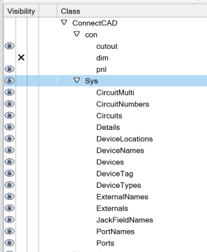
I'm considering cleaning up my classes and placing the ConnectCad classes all under a ConnectCad class group. (see below)
Do you foresee any issues if I move the default ConnectCad classes around?
-
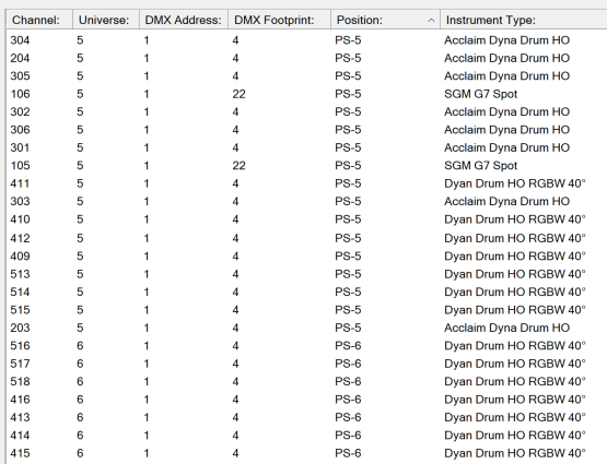
In the new 2020 DMX patch window, is there any way to define a secondary sort? In my example below I'm sorted by position. But when sorted this way, the channels have no logical order.
I would love for there to be a way to define a primary sort and then a secondary (which in this case would be by channel).
Anyone have any tips?
-
 1
1
-
-
Thanks guys,
I must have been blind earlier... I found the Replace with Symbol function and that did the trick.
-
I was hoping for a somewhat more automated process as this still sounds pretty click intensive to locate each group and manually place my new symbol and delete the group instance. But it is what it is.
Thanks for the response.
-
I have a DWG from an outside vendor that I have imported. There are a number of devices that came in as groups and not symbols. Is there a function in spotlight where I can select a group and then replace with a symbol?
Looking at the online VW manual, it seems that this function exists for Landmark and Architect. https://app-help.vectorworks.net/2020/eng/index.htm#t=VW2020_Guide%2FSymbols%2FReplacing_objects_with_symbols.htm&rhsearch=Replace Objects&rhhlterm=Replace Objects&rhsyns=
Is there a similar workflow for Spotlight users?
-
Could you just duplicate the circuit line from J1-J2 to K1-K2? Since its already its already formatted the way you want, you should just be able to duplicate it and drag onto the K1-K2 circuit.
-
1
-
-
@PVA - Jim Has anything like this been implemented into VW yet?
-
I edited the VW version as I don't have autoplot. I realized the issue was that I renamed the "connector" parameter to "cable type". VW did not like that and all of my jumper cables disappeared. Once I changed the naming back, everything is back and working as expected.
But just for my knowledge, is there an easy way to restore a built-in plugin back to defaults if needed?
-
I've been playing around with adding custom connectors to my jumper plugin and I must have broken something.
Is there an easy way to reset a plugin back to default?
-
In the rack elevation view, make sure your 2D racks are located in the correct rooms. Looking at your test file, a lot of the devices that were created by the "update rack elevation" function are set as "non-rack" devices. Make sure these are set to either full or half-rack devices and also make sure the RU height is set correctly.
With all of that said, I'm also having an issue in your file though. When I set devices to "full-rack" and set an RU height, the width of the devices are changing to 0". I suspect this might have to with your file having units set to feet/inches.
As a test I copied all of your schematic devices to a new blank ConnectCad file using the ConnectCad.sta template (which is metric by default). I then used the "update rack elevation" function and created a new room and rack. I was then able to add equipment to a rack as expected.
@Conrad Preen Any thoughts?
-
1
-
-
8 hours ago, Conrad Preen said:
We could do that. It wouldn't be anything very exciting - just set the drawing units to feet and inches and set a suitable grid size probably 1/4 inch.
Something as simple as that would be great to have included with ConnectCAD so users can hop right into either template that works for their project.
-
On 4/29/2020 at 11:02 AM, Nikolay Zhelyazkov said:
Okay, seems like we are not supporting imperial units in the dialog and it counts them as invalid input.
Along the lines of Metric vs Imperial units.... Are there any plans to create an imperial ConnectCAD template that could accompany the metric template?
-
On 5/6/2020 at 3:51 PM, markdd said:
You could make the projector into a lighting instrument symbol and convert it to a lighting device. The Ligting device object will move the 3D independently of the 2D leaving the 2D component in place.
Hey Mark,
How do you do this? I'm currently working on a file with all my lighting fixtures in 3D. But for the 2D instances of the hybrid symbols, I'm trying to find a way where I can move them at bit to clean up some overlaps, but don't want to mess with the 3D positioning.
Currently when I move the lighting device in 2D plan, it is also moving the 3D. (and vice versa) -
I just downloaded your test file and got the locations to populate by just selecting all the gear in a particular room and then moving them just slightly. That seemed to refresh the location information and then the appropriate room name populated in the schematic view devices.
-
Hi Conrad, I hear your reasoning as to why this functionality was never developed for ConnectCAD. But I have to say, coming to ConnectCAD from VW Spotlight, I'm really struggling with this.
On a current project I'm working on, I have 204 of the exact same device drawn. These are simple lighting fixtures with an input and an output. Now what if need to change the connector type on all of these devices? Do I have to edit each device individually?
Even if ConnectCAD doesn't go the route of updating devices via symbols in the resource manger, is there a way users can do some sort of find and replace function to save time and clicks?
Is there anyway in the currently released version of CC to make these kind mass edits easier?
-
Can't wait for this feature to come back. I was pulling my hair out yesterday when I would duplicates devices (option + click drag, not copy paste) and devices were still landing off grid sometimes.
-
On 4/16/2020 at 8:55 AM, mcschaefer said:
Do you have any suggestions for how I can synchronize this data across multiple machines? I'd hate to have to remember to do it manually. As we grow and add more seats this becomes more and more important.
This would be a fantastic feature! We have 12 seats on our network license and everyone is working on different signal types and connectors files. Would love to see a way for this to stay in sync for all users.
-
On 4/14/2020 at 7:23 PM, S. Leathers said:
I know I am very late in responding, but curious what you ended up doing. I don't know the correct procedure or recommendation here. I had a similar situation. Ultimately, I finished the 2D plot so I could show data as desired for the crew. Then created a 2nd plot just for 3D export to MA, that placed lights in their actual location in terms of x, y, z.
I also work a lot with Rep plots-long story short my work flow is such that I cannot/do not place all fixtures on the same layer. Because of this I find using the Create Plot and Model view cumbersome, and ultimately unhelpful. However, anyone I ask about this tool says it is confusing and does not yield the results they desire.
Workflows have changed a bit going into v2020. The Create Plot and Model View function has now changed into Create Schematic views which allows you to have 2D representations of your non-horizontal 3D lighting positions. There are still some challenges with the Schematic Views (and hopefully some future improvements) but you can find a lot of conversation and tips regarding them on these forums.
At the end of the day, I'm doing my best to create all of my drawings fully in 3D. With a combination of 3D label legends and the possibly schematic views, it's still relatively easy to create clean plots for your crew while still keeping your drawing in 3D for export into pre-vis software.
-
Thanks Mark. Is there a way to toggle those off in viewport settings or via classes? I have 13 viewports on this sheet and only need to show the legend once. Currently it seems that I will need to go into each viewport's annotations one by one.


White Model Render Style
in Entertainment
Posted
When you edit your sheet layer, what is the DPI set to? Also what render mode are you using? OpenGL?