
JustinVH
-
Posts
597 -
Joined
-
Last visited
Content Type
Profiles
Forums
Events
Articles
Marionette
Store
Everything posted by JustinVH
-
Hello Mario, I am glad that the video was helpful. The best way to place a moving light on top of a vertical truss is as follows: -Insert the light using the Lighting Instrument Tool and use the insertion point for the light as the center of the end of the truss. Be sure you are in a Top/Plan view when you do this. If you are using a lighting instrument from the Resource Manager they are all designed to be inserted hanging in the down position. This of course means that your light is inside the truss as it is hanging down. -To correct the issue of the light hanging inside your truss, select the light and scroll down to the bottom of the Object Info Palette until you see a check box labeled "Set 3D Orientation". -When you check the Set 3D Orientation Box you will activate a X Rotation and a Y Rotation dialog box directly below the Set 3D Orientation box. -If you enter a value of 180 in the Y rotation dialog box your light will rotate so that it is standing up instead of hanging down. -You may have to adjust the Z height of your light to get it to rest on top of the truss but that should be it. In a side view your light will be sitting on top of the vertical truss and pointing up as opposed to pointing down. I hope that helps. Justin
-
Hi Scott, Those truss crosses are showing connection points of other objects that are sitting either directly on top of the truss or directly underneath the truss. Basically, like a cheeseborough or a rotolock connection that is showing a connection to the truss. In the OIP you can choose to make this connection pliable (like a span set) or rigid. You can use it for placing truss on top of other pieces of truss or cantilevering a lighting pipe using the Lighting Pipe Tool off of a truss. It looks like there are many truss crosses that you did not intend to use as I do not see any reference objects connected to them. I have found them on truss to truss and truss to pipe connections but nothing else. Did they just appear on their own?
-
Glad it worked for the straight pieces. For the cubes do the same thing and line up the cube so the left side of the cube is at the symbol insert point. Place a loci that is on the insert points class at each connection point on the cube so that you have a total of four loci in the symbol. You should also do this in the 3D version of the symbol using 3D loci and make sure that both the bottom of the truss and the 3D loci have a z height of zero, basically sitting on the ground. This should get everything connecting properly using the symbol insert tool. If you have any issues send me the file and I can take a look for you but it sounds like you are getting the hang of it.
-
That makes sense for the symbols overlapping on top of each other. If you use the symbol insertion tool instead of auto connect do your truss sections join at the loci that are on the insertion points? For the Braceworks auto connect to work the truss sections and corners have to be set up so that the left side of each section is at the symbol insertion point in both the 2D and 3D. Let me know if the trusses will at least connect properly using the symbol insertion tool.
-
Hello Simon, Have you connected the appropriate record to your truss symbols and set up your Braceworks connection data properly? Also, are you using the new rigging classing for the truss symbols that uses insert points?
-
Not a problem. That Hanging Angle also will allow you to choose other angles so that you can create trusses that hang on the diagonal when viewed in a front view.
-
Hi Mickey, If you are using the Insert Truss Tool with an existing horizontal symbol you can make that truss into a vertical truss. In order to do this using the new tool simply change the hanging angle to 90º in the Hanging Angle selection box next to your active symbol. When you insert the symbol it will be a vertical truss instead of a horizontal truss. As there is no existing geometry for a vertical truss the Resource Manager will create a vertical truss that is a 3D symbol with the rest of the truss symbols in the document. I attached a quick video to show you the process. Vertical_Truss_Drawing.mov
-
@mjm I did a very quick test using a single light and focus point on an extruded floor and in OGL the light was rendering with the chosen Color Filter. As the rendering was in OGL the Color Filter changes were occurring live once I pressed the tab button to set the color in the OIP.
-
Hello mjm, I completely agree with you about how tedious it is to individually select and edit lights using the "Edit Light" window, I remember how frustrating it was to select each light one by one as I did not want to edit one light and duplicate as I already had my plot laid out. One of the features that has been added and released in VW2018 SP2 is the ability to use the "Edit Light" window globally just like the OIP. Now you can select multiple fixtures and use "Edit Light" to make changes and it will apply to all selected fixtures. It is a timesaver for sure. You beat me to the punch on my reply as I was typing when your reply popped up!! I am sure that you will find this new feature very helpful.
-
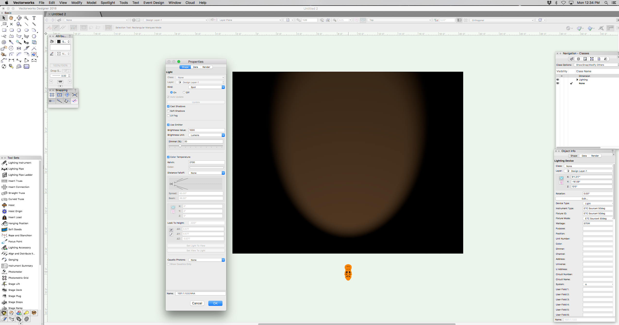
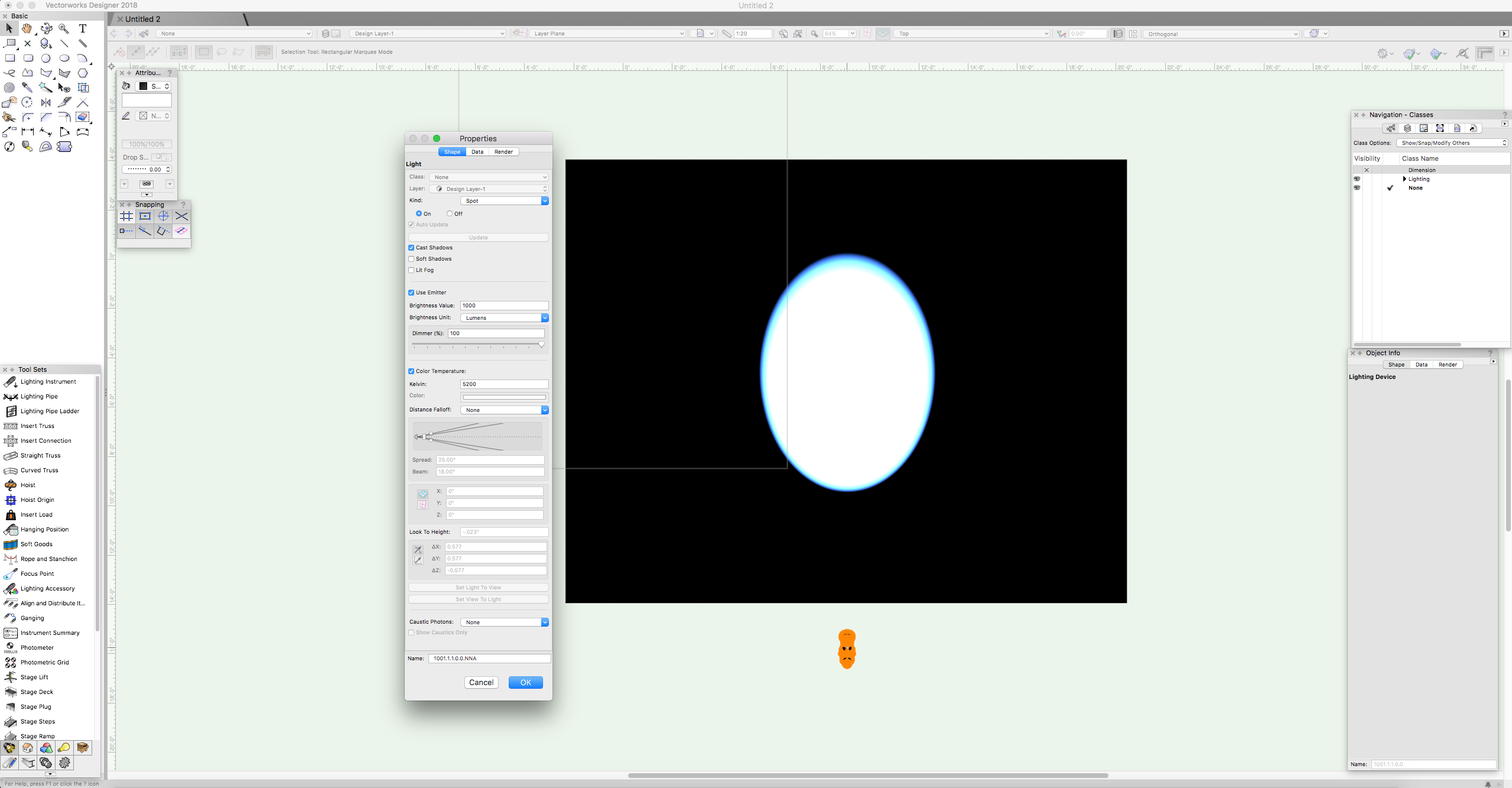
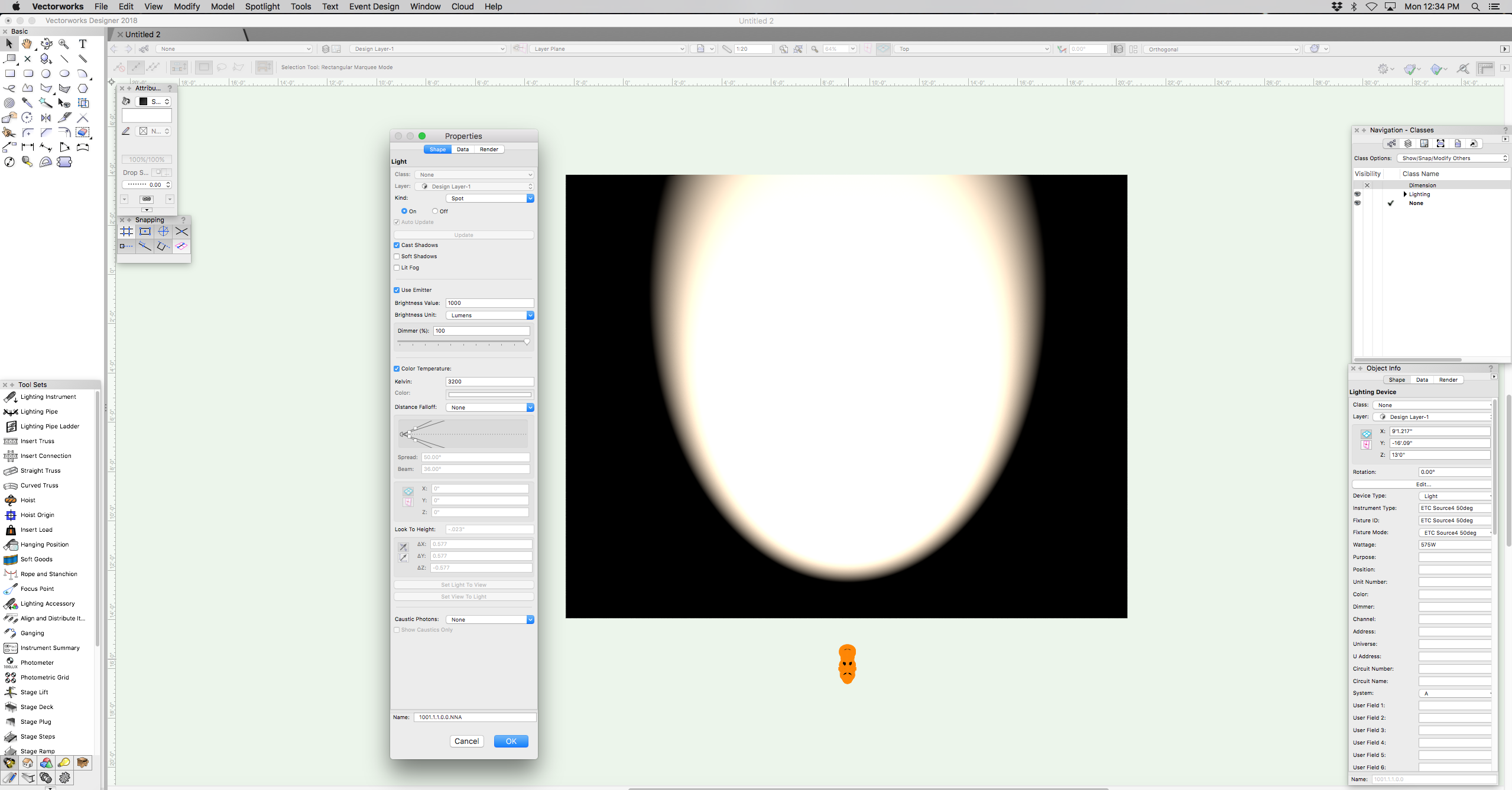
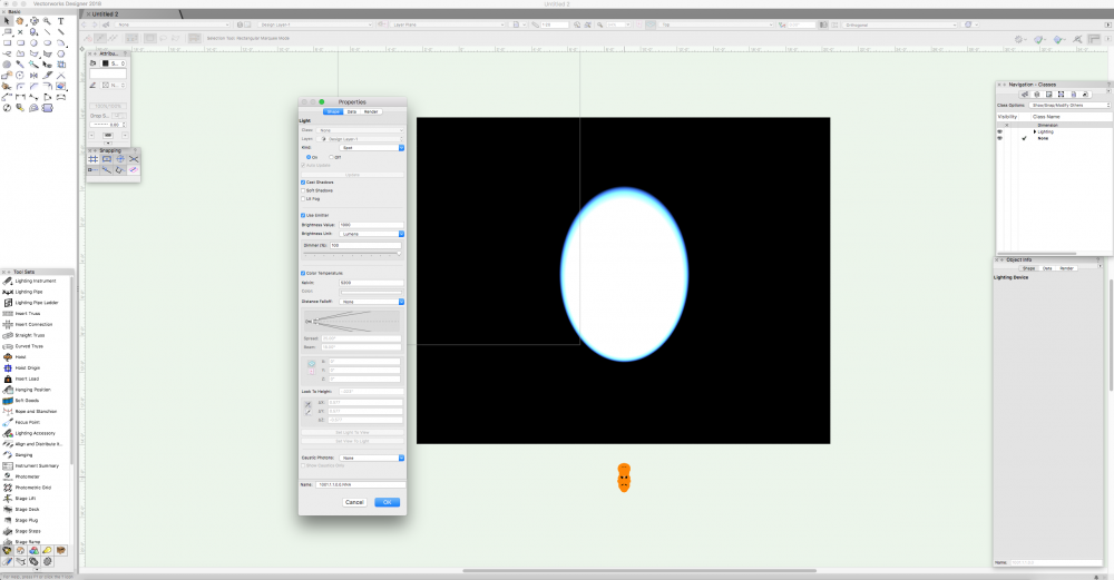
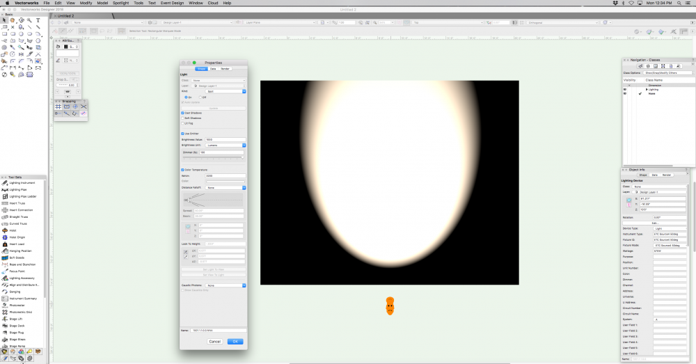
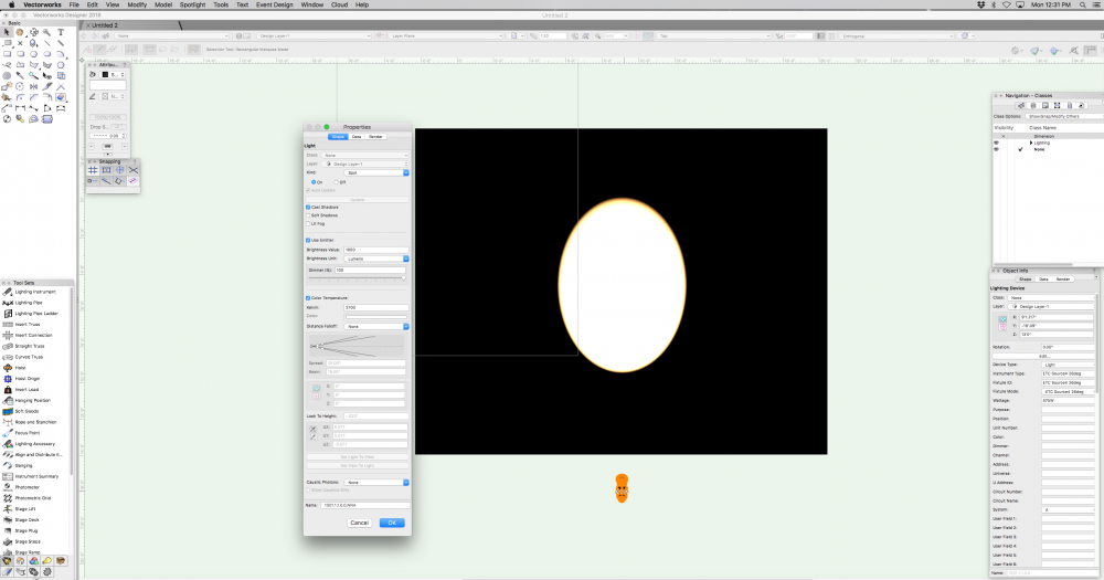
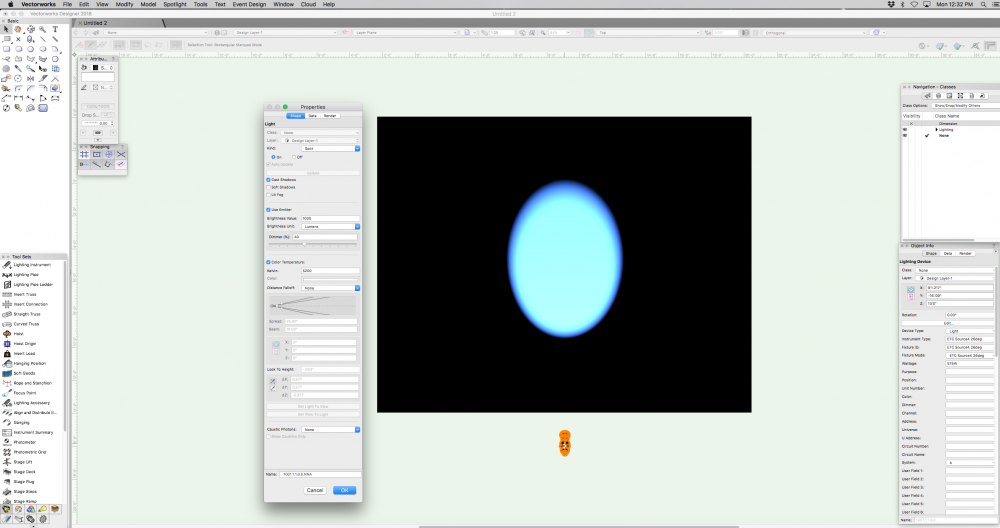
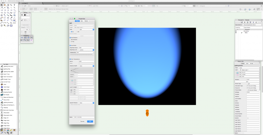
Hello @Champiyann, What you are trying to accomplish can be done in Vectorworks. When you are in the Edit Light window as you mention make sure that you check the "Use Emitter" box so that you can choose the color temperature of your light. If your lighting instrument's beam is too narrow for what you are focusing on the light overpowers your color temperature and you will see white when rendering with some color at the edge of the field. Also, if you lower the intensity of the light with the dimmer option in the Edit Light window you will reduce the overpowering white and begin to see the proper color temperature that you selected. One final thing is to make sure that you either turn off or reduce ambient lighting in View>Set Lighting Options> Ambient Info. If your ambient lighting is too high it will overpower your entire rendering and you will have difficulty making out the color temperature differences. I have attached a few screenshots to show some different settings using the Edit Light window so you can see how dimmer and field angle change the color temperature intensity. The smaller diameter beam is a 26º ERS and the larger beam is a 50º ERS. My ambient lighting is off in all of these images. Hope this helps.

-
@markddI did not create the truss symbol that you used in your file so I cannot say what technique was used unfortunately. I know that when I do make truss I like to use a traditional extrude for each piece and rotate into place as I feel I do have a bit more control. Once I am comfortable with the placement of a single piece of lacing I use alt+click to duplicate the piece and move it into place along the truss. I have not yet made the particular style of truss in your example as I have worked on traditional US box truss styles but I think I would still work in segments to get one component correct and duplicate and move as necessary until I can perform the solid addition. Justin
-
Hi Kevin, Your example is a nice result and is a much better reproduction of the original object. Why don't you and Mark take care of submitting the bug as the two of you discovered the issue as well as the workaround solution. Justin
-
I am glad that you were able to get EAP to work. When I drew your poly line I used the corner vertex mode and drew straight lines from arc end point to arc end point using the snapping to make sure I was drawing using the correct vertices. I have attached the file showing my poly line which I drew using your original poly line and my resulting EAP in red. I hope this helps. Justin Truss_Lacing.vwx
-
@markdd I took a look at your file and I tried to create the extrude along path using your poly line and had identical results. I then tried to recreate your poly line using corner vertex points instead of arcs and when I did an extrude along path the result was nearly identical to the VWX truss lacing. I know that when I create truss libraries for VWX I use extrude along path for all of the lacing and perform a solid addition to marry the lacing to the chords. Sometimes it does take some fiddling to get all of the extrudes to combine to one solid addition but usually it is one extrude that is causing the issue and copying an identical extrude from another portion of the truss and pasting it in place solves the issue.
-
Hello all, Thank you for your input on the PixelFLEX LED panels. After reading the comments and feedback the symbols will behave similarly to the truss which contain both a complex and simplified geometry. The Video-LED class also contains a solid on the front of the panel for adding a texture or logo if desired. The complex geometry shows the input and output points as well as connection points to interlock panels and some hanging brackets as well.
-
Hello all, Thank you for your responses so far. I failed to qualify my initial question properly and I apologize. I am one of the content developers for Spotlight at Vectorworks and I have begun creating a new library of for the PixelFLEX line of products. I am just looking for some user feedback as to the preferred type of symbol for LED panels regarding simple 2D extruded rectangles vs. a more accurate 3D model showing connection points, handles and input sources. As I am not designing for the field nearly as much as designers using Spotlight I just would like some ideas to gain a better perspective on how the resources will be used while drafting and rendering. Thank you.
-
Hello all, I am going to begin creating symbols for PixelFLEX LED screens and would like some user feedback. In the past LED video screens have been either detailed geometry or simple rectangular plug in objects. As a user which style of symbol is preferred for video screens, detailed geometry showing top profile and connection points or simple plug in shapes? Any input is greatly appreciated. Thank you!