-
Posts
1,474 -
Joined
-
Last visited
Content Type
Profiles
Forums
Events
Articles
Marionette
Store
Posts posted by Marissa Farrell
-
-
I think we're on the same page!
The node would have an OIP popup for your desired output unit, the node itself would look at the current document units and convert the input to the unit you've chosen.
I'll look into this.
-
 2
2
-
-
I'm trying to wrap my head around this to find you a solution.
1) I assume you always report pricing by sqft?
2) You occasionally have drawings that use other document units and need to *always* convert the pricing to sqft?
I think a solution would be a conversion node that takes current document units and allows you to convert a value to a different unit defined in the OIP. Would this be a valid solution for you? (This won't be a quick node to create in full, but should be easy to start if you're only looking to do one or two unit conversions.)
-
-
2 minutes ago, Phileas said:
Do I understood this right:
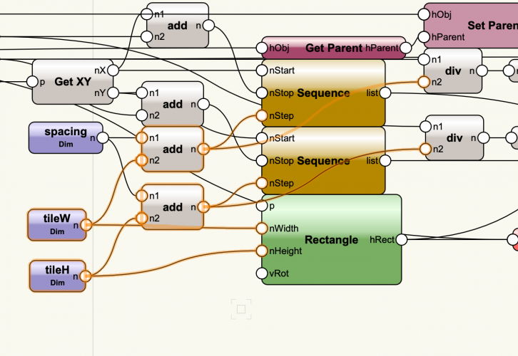
You used a Dim node to set both the width and the height of a tile, since they are the same (?). That means that if I wanted to wrap up the nodes now, I'd only be able to make the tiles bigger or smaller squares, but never rectangles with a different width/height right? Cause I'd only get 2 parameters: TileDim and Spacing (if I got this right)
Yes, that's correct.
I'll throw together a change with independent width/height for the tiles.
-
 1
1
-
-
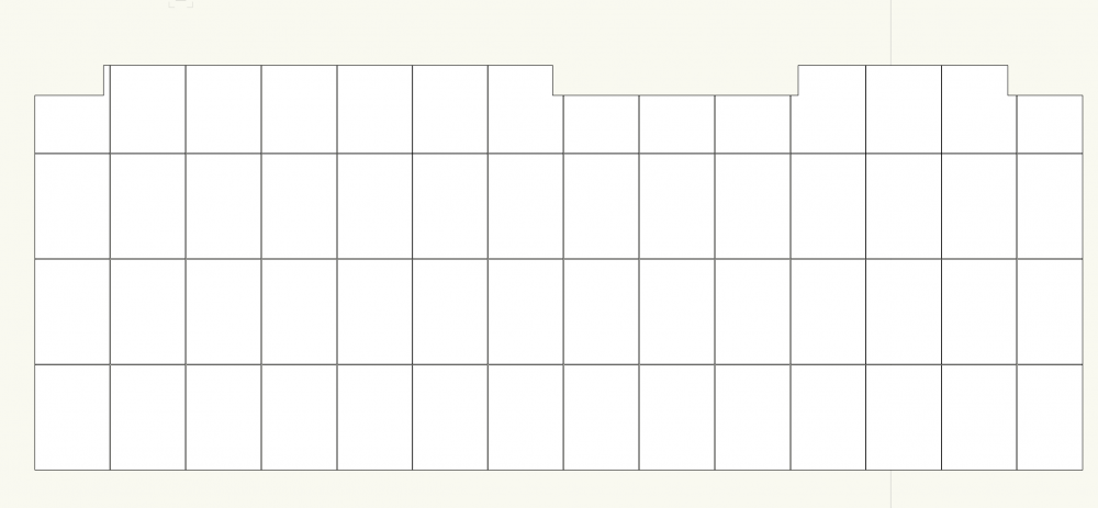
So - I've gotten started on this, to the point where you can cut the rectangles down to size.
The slope won't be taken account in this revision.
There is currently an issue where there are multiple coincident objects remaining (I'm looking into that now, it's a result of a Planar Boolean node but that we haven't yet solved)
I have not extruded the "tiles", they are just polys at this point.
I wrote the script in 2019, but exported back to 2018 since the file you shared earlier had to be converted to 2019, so I assume you're using an older version. Everything *should* work, but please let me know if you find otherwise.
-
 1
1
-
-
I can help you! Could you send me a file with that base shape?
-
 1
1
-
-
Unfortunately at this time, the Intersecting Line nodes only work with Line objects, not Polys.
I've attached a network that will do what you want, and I'll make a note to look into creating a node (or possible updating the existing node) to work with polys as well.
The attached network breaks a polyline into individual segments and checks each segment to see if they intersect with the line.
I haven't tested it extensively, but it seems to work okay. Please let me know if you find any issues.
-
OIP stands for Object Info Palette.
(fun tip - if an acronym is used regularly here and has a dotted line beneath it, hovering over it with your cursor will display what it stands for.)
-
 1
1
-
-
@Tamsin Slatter is correct that you are limited to 8 lights in OpenGL.
-
 1
1
-
-
Additionally - have you updated to 2019 SP 3.1?
-
Hi!
Would it be possible to send me the files that you are having issues with privately as well as which cells you're editing when encountering the issue? I'd like to see if we can reproduce and submit a bug on your behalf for our engineers.
Thank you!
-
I'd like to add to @SMannVW and state that you could use the Interactive Appearance Settings button in the Interactive tab to change the highlighting of locked objects.
In the Interactive Appearance Settings dialog, there are two options you may want to modify:
- Object Highlighting - Locked
- Object Highlighting - Pre-Selection - Locked
If you change both of their Opacity sliders to 0, objects will not highlight ever when they are locked. If you would like to keep the locked objects highlighted when selected, only change the second option.
-
 1
1
-
Also, @IJSSEL provided an example that unfortunately gives an identical failure, which is still where I am stuck. You cannot have both mirrored, when Y is checked, checking X makes no difference.
-
12 minutes ago, IJSSEL said:
Valve nodes work like that ( I think.)
The only thing a valve node will do is suppress anything beyond it in the network - since neither of the valves in this node connect in any way, they will remain independent - there is no issue with this network with regards to Valves.
-
I'm looking into this for you, though I'm at the same crossroads you found yourself at 🙂
I'll let you know if I get anywhere with it, it may just be that the symbol isn't enjoying being mirrored, though I'm unsure at this time. (My test axis drawing is working fine, the mirroring is the only thing failing - I'm hesitant to blame it on the Valves.)
-
So, I looked into this today and unfortunately at one point we introduced a method behind-the-scenes to fix a bug in Marionette Objects (they weren't always drawing correctly when in a 3D view) that saves and restores the current view after a Marionette network is run.
Because of this, unfortunately there's no way to set a view using a Marionette network.
I put in a request to look for an alternative method to solve the Marionette Object issue which will directly fix this issue and I'll try my best to let you know if and when that happens 🙂
-
I don't believe we have a node in default content that will work for this, but I can look into providing you with a custom one.
The Set View Matrix node does not appear to work in the way you'd wish (I've never used this node and am not exactly sure what its application would be)
-
There are a couple of options for this.
1) If you want to run a script on selected shapes (or shapes by a different criteria), you can create a Marionette Menu Command using the Objects by Criteria node with criteria of Selected (this can be populated in 2019 by using the Criteria configuration... button in the OIP). This object will not be tied to Marionette directly after the menu command is run and will limit your customization abilities.
2) If you want to be able to reshape the starting shape in the future, you can use a Control Geometry node and place your starting shape in the Control Geometry group of a Marionette object. This will remain as a Marionette Object (which is similar to a plug in object) and will refresh when edited.
I'd be more than happy to go over either method (or both) with you if you need some direction.
-
vs.PutFile() is used for text files, but you want to create an image file.
I suggest building your path using vs.GetFolder()
You also will not need to use vs.Close() after making this change.
fileName = vs.GetFolder('Choose path:')[1] + 'image.bmp'
(You need to extract the second output from GetFolder, which is why the [1] is after it.)
-
There currently aren't nodes for native worksheets in the default content, though I've also written a handful of those. Either way, we can get information in, so it's whatever you think will work best for you!
-
You can customize the Popup List node in the library to contain these choices. In order to do so, you will need to delete the line at the very top that begins with #COMMAND
You can edit the values you want displayed in the 13th line.
The output will be an integer, the outputs start at 0, so if you select the top item in the list, the output will be 0, the second item in list will be 1, and so-forth.
You can then use an Equals node to define your boolean input to the valve nodes.
Let me know if I need to clarify better 🙂
-
 2
2
-
-
If the excel file is saved as a .csv, you can use the nodes in the File I/O category to pull information from it.
I don't have any examples handy, but I'll make a note to try to get something simple together.
-
 2
2
-
-
Great! Glad you were able to find a solution 🙂
-
Yep, I was going to guess that if you're single-clicking that you might have a mouse issue.
A quick google search brought me to this site which might let you test some click events?
-
 1
1
-


Any Marionette Experts here?
in Architecture
Posted
You're definitely on the right track!
I'll try to find some time later today or tomorrow to write up what's happening. I'll also look into chunking the network into wrappers to make it easier to understand in parts 🙂