


Marissa Farrell
-
Posts
1,474 -
Joined
-
Last visited
Content Type
Profiles
Forums
Events
Articles
Marionette
Store
Posts posted by Marissa Farrell
-
-
I would suggest using an Ordered List node to assign the order of the creation. There's no real way to determine the order of inputs to a single port if many wires enter it; the Ordered List node will ensure that the values are passed in the order you've specified.
-
 1
1
-
-
This usually means that the profile is not a closed polygon, also, you will want to leave it as a 2D poly.
Can you attach a file that contains the profile? I, or someone else, can take a look for you.
-
1) You can use either single or double quotes, it does not matter as long as you open and close with the same type.
2) Marionette networks cannot be run on selected objects unless you convert them to a Marionette Menu Command, though I am not certain, I am assuming that is why you are getting a false count of 16 while running in debug mode.
3) Currently, using the button on the Objects by Criteria node will always revert that dialog back to the defaults. As long as you don't hit OK in that dialog, your previous criteria will remain the same. There is currently a request in to have the Criteria dialog display the current criteria from the OIP when the button is pressed.
4) You can use Control Geometry to define your source geometry as an alternative to the name node and then create a Marionette Object (which is basically a Plug In Object that uses a Marionette script as its code). I'm not sure if this would fit your needs, but if you'd like more information on it, I'd be more than happy to go into further explanation.
Hope this helps!
-
Taking a quick look at your script, this may be as easy as adding quotations around your output values (I am assuming these are the strings you use for naming your profile?)
For example
if input == 3:
        self.Params.output.value = "K5"
-
You can move your Extrude Along Path upward using the Move node, or you can extrude legs below the EAP. Once converted to a Marionette Object, it can move around freely. The Marionette Object has its own coordinate system that you will use to move/place your individual parts.
-
You can create your profile the same way I got around the compose issue - determine the location/drawing order of your vertices and feed them into a Poly node.
Using the Ordered List node allows you to order the points that are going into the Poly node, if you were to just wire them all into the same port, the Poly node could take them in unpredictably. Ordering them ahead of time will ensure that they are drawn exactly how you expect.
For example, a square profile - you would provide it 4 points (0,0), (0,1), (1,1), and (1,0) into the first four ports of an Ordered List node, placing a Polygon 2D node after it. You then have two options; you can use the Set Closed 2D node after the Poly node, or you can wire the first point, (0,0), into the fifth port of the Ordered List node (item4).
I hope this helps, but if it doesn't, feel free to keep asking for clarification 🙂
-
I took a look and made a few changes to your network - I didn't edit the one you have on your drawing area, but I did redo the one inside of the Marionette Object.
I hope this helps - basically the "compose" node was failing to compose the lines while in a Marionette Object, I'm going to submit a bug for that since I'm not sure why it works in a regular network, but not in an Object.
Please let me know if you need any help improving this further!
Marionette-ExtrudeAlongpath-OfficeDeskCounterTop_MFarrell.vwx
-
2
-
-
Attached is a file with a revision that should work for this use case, I'm sure there's a reason I didn't go this route initially, but I can't recall why.
There's also a chance I had fixed the issue you're experiencing in a more recent node, though I'll have to dig through some files to see what my latest revision was (though I'm sure it's more recent than Nov 2018, as dated in the node you've been using)
-
 1
1
-
-
Hmmm. This should be running correctly, there's nothing wrong with the code that I'm immediately seeing.
I'll look into this.
-
There's not a traditional method of looping in Marionette, but if you incorporate the Sequence/Range/Series nodes, they can help to facilitate behavior similar to a loop.
Take a look at those, and if you need some guidance let me know and I'll try to find some time on Monday to help guide you 🙂
This will just be a matter of list manipulation, so check out all of the Data Flow nodes.
-
I think the best way to get started is to script something you already know how to make WITHOUT scripting.
Write out a list of the steps you take when drawing something, and then look for nodes/functions that would help accomplish that for you. For Marionette, if you aren't able to find a node to do something, ask in the forums; sometimes it's been created but not added to default content, and other times it can be made for you quickly.
Start small and build from there. If you want to do something complicated, try doing the smaller parts of it first and then expand on it.
-
1
-
-
One approach that I can think of is to create multiple square grids and offset (move) some of them to give you the appropriate points for an isometric grid.
I'll try to find some time to experiment later, but maybe that can give you a head-start on me towards a solution 🙂
-
I'm attaching an example to get you started - it still needs some error handling and modifications to get exactly what you want. I've added a new layer for the Control Geometry example, and I've modified your original network on its original layer.
Let me know if you have any questions!
-
Great question!
- Ungroup will actively ungroup a group (unless it's a group created by Marionette) and return the handles of the objects that used to reside within it
- Contents will give you the handles to the objects within a group without ungrouping it.
Generally, they can be relatively interchangeable if you don't really care about the grouping of objects in the end, but in this case (though I'm not totally certain) I believe it fails because once you ungroup the objects in a Control Geometry container, the node that references Control Geometry doesn't know what to do anymore since it's only supposed to contain one object (ungrouping would result in the Control Geo container to now contain three separate objects).
I hope that helps to clear things up at least a little bit!
-
I would suggest instead of using the Ungroup node, use the Contents node.
I've attached a revised file.
-
The chunk node *does* work on curves, the issue is that the Divide Curves node does not understand how to use that input.
Here's a network that I think accomplishes what you're looking for. What you'll need to do is just approach things a little differently - manipulate your lists later on when they're not objects and are instead point data.
I included valves at the end to show you different results - when you just generate curves, you're missing the last point which doesn't give you a closed curve. The easiest way to circumvent that is to first create closed 3D polys then convert to curves afterward (You could, of course, manipulate the points instead as you did in your wicker file.)
-
1
-
-
I'm attaching a simple example - hopefully it will help you better understand the Chunk node.
How the Chunk node works - you provide it a list and an integer. The integer represents how many elements you want in each list, in my example (based on your example text), I want 10 elements in each list.
The output is 5 lists of 10 items.
Marionette_ChunkingLists_MFarrell.vwx
I also modified the network in your attached file to update it to what I *think* you wanted to do.
Also - I do hope you'll give me my bonus points 😉 The handle types can be found here: http://developer.vectorworks.net/index.php/VS:Function_Reference_Appendix#objects
-
2
-
-
I've started on this, but hit a bump that I need to spend some more time on.
I'm attaching my progress below.
The issue is that there are still some outlying points that I need to find a way to filter out; otherwise, I believe it's performing pretty well. Please let me know if you find any issues.
-
1
-
-
Great question! We currently do not have any nodes that support stories, but I can certainly add them to the list of things we should include.
I can also look into how difficult it would be to make some "Version 1's" of these and try to attach them here at a later time 🙂
-
In 2018, there is the Remove node which has two inputs, one is for the list and the other is for the item you want to remove from it.
2019 introduced a Remove Duplicates node. I've attached a 2018 file with it. This node will remove all duplicates.
-
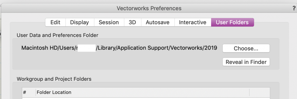
No problem! Navigate to your Vectorworks Preferences and go to the User Folders tab, in the top section called User Data and Preferences folder, there's path listed and a button that will allow you to navigate to it. Hope this helps!
-
Although I'm not sure why that's not working, it's recommended to not modify files in the App folder - they may get overwritten during Service Pack updates.
Try creating a new file in your user folder using the same pathing as I mentioned above and see if that fares any better, that will ensure (as long as you don't delete it yourself) that it won't get overwritten.
-
I think that file may only cater to Menu Commands. I would suggest creating a whole new file with a new name and trying again.Scratch that - are you talking about the file in the Application folder and not the user folder?
Just trying to get some clarification 🙂
-
@Phileas - Great question!
One way to include custom nodes in your library is to create a file at this location
[Your User Folder]/Libraries/Defaults/Marionette
Once the file is created, save any nodes you want to have access to as Red Symbols. (in Symbol Options, make sure that "Convert to Plug-in Object" is checked.)
The other way follows similar rules - you can create a Workgroup Folder on your network to allow others access to the nodes as well. I personally use my OneDrive folder to share between my 3 computers. The setup is a little more time consuming, but if you're interested, I could walk you through that.
Once you've set up the file, you'll need to go to your Resource Manager and choose "Refresh Libraries" to get them to appear in your tool popup.
Please let me know if you have any issues and we can troubleshoot together.
(and as a final sidenote - the Class Popup node was added in Vectorworks 2019, as well as ~50 other new nodes 🙂 )

Help with Polygon and extrusion
in General Discussion
Posted
So I found the issue and fixed it -
On the inner edge of the left side of the profile, there must have been two lines overlapping when you composed because stepping through the vertices bounced back over that edge once before continuing. The poly was also not closed.
I've attached a revised file, exported back from a newer version (you should have no issues opening it, please let me know if otherwise). You should be able to extrude this shape as a solid (I tested and undid the action to make sure).
websters upstairs v1.3_MKF v2018.vwx