


SBarrettWalker
-
Posts
335 -
Joined
-
Last visited
Content Type
Profiles
Forums
Events
Articles
Marionette
Store
Posts posted by SBarrettWalker
-
-
You would need to create a custom node using the formula vs.GetPluginStyle(hObject). I created one in Vectorworks 2023.
-
 2
2
-
-
As for the styles that are in the feature video, they were customized from the the existing styles in the default library. I think the library technically has all the different possible "dynamic texts" that you might want, but there is probably not a style that would match exactly what you need. It is a hard balance not to overload the default library with tons of styles but to make sure enough are there to help someone find something customizable. I am attaching a file with all of the elevation benchmarks used in the new feature video that weren't from the default library.
-
3
-
-
- Popular Post
- Popular Post
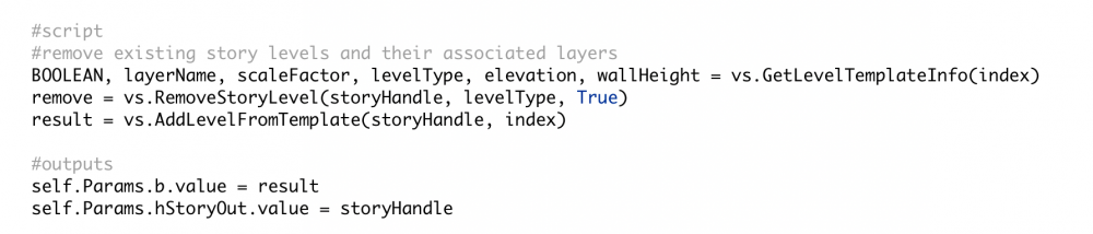
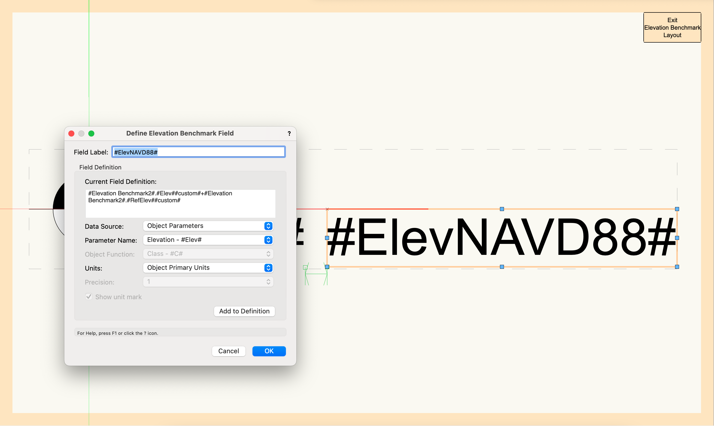
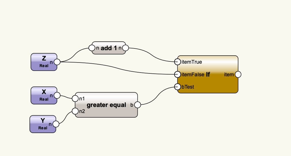
Hi Max, you were on the right track, but you need a different formula to read the project elevation + the reference elevation. I believe the new feature video shows a different field value, the one for project elevation. The reason the formula looks so complicated in the video is it has a fancy IF/THEN statement to show a "+" in front of the value when it is positive. Attached is a screenshot of what the formula should look like and a short video on how I built that formula. I removed the IF/THEN statement to make it a little simpler, but if you really want to have the plus sign in front of the value, I recommend you set it in the "Prefix" field of the Elevation Benchmark settings as that is simpler to report. I have also attached a screenshot of what the formula would look like to report the prefix along with elevation + reference elevation. This new tool is very powerful, but it can be complex. There are default styles that try to cover most scenarios, but if you have suggestions on what to include in the default libraries to make the styles easier to use or to understand that would be welcome!
I hope that helps,
Sarah


-
7
-
 1
1
-
@MaxStudio Make sure that there aren't any other characters in the name like "-" or "/", only numbers and letters. I can't remember if spaces could be used in 2016 or if it had to be underscores.
-
I also would like to mention that there is a Batch Rename command in the Tools menu that allows you to find and replace, add prefixes, suffixes, etc. This was not available when the Rename Classes Marionette menu command was posted to the forum. Because you would have to run it and set it every time you opened a new file, the menu command wouldn't really be any better than using the Batch Rename command.
-
2
-
-
@E|FA in order to reset the default mappings, go to the settings dropdown in the top left corner of the Data Manager and choose Vectorworks Defaults. This will reset all of the mappings that you have done. Unfortunately, there isn't an easy way to partially undo your mappings. If this works then great, but if you are still having issues, you can send me the file and I will look it over.
-
Hello @E|FA,
I was able to get #WS_OBJRVALUE# to read the correct R-Value of an object, even if it is overridden manually. I have a attached a file that has a working data tag. This file also has R Values and U Values mapped to a custom record. Doors, Windows, and Walls all have their R- and U-Values mapped in the Data Manager, so even though it is in a custom record, the value is coming from the object and the record is automatically attached to the correct objects.
-
1
-
-
You should know that there is a data tag (new in 2022) that will read the height of any point you click on. It is in the Spot Elevation folder of the tag in the default library, and if you have your layer plane set to automatic and click on the horizontal face of an object, it will read the real height of that face. If you click on a vertical face, it will read the height of the point at which you clicked. I would give this a try first to see if it will work for you instead of building something custom in Marionette.
-
2
-
-
- Popular Post
- Popular Post
On 9/15/2021 at 1:51 PM, Tobias Kern said:Hi,
thnx for the new VW 2022.
I have to wait until end of october, before we, here in Germany get the new localized version.
I have one question, maybe someone could investigate for me.
In VW 2022 we got a enhanced wall tool with new wrappings.
Got we also formulas (area, length, volume, material, separatable into horizontal an vertical wrappings
because often the horizontal wrapping on the bottom inside/outside is made of different material)
to calculate the data of the wrappings in tablesheets?
I mean, are the wrappings only for a better visual representation, or is it more of a whole bim package?
Greeting and thnx in advance!
Tobi from Germany
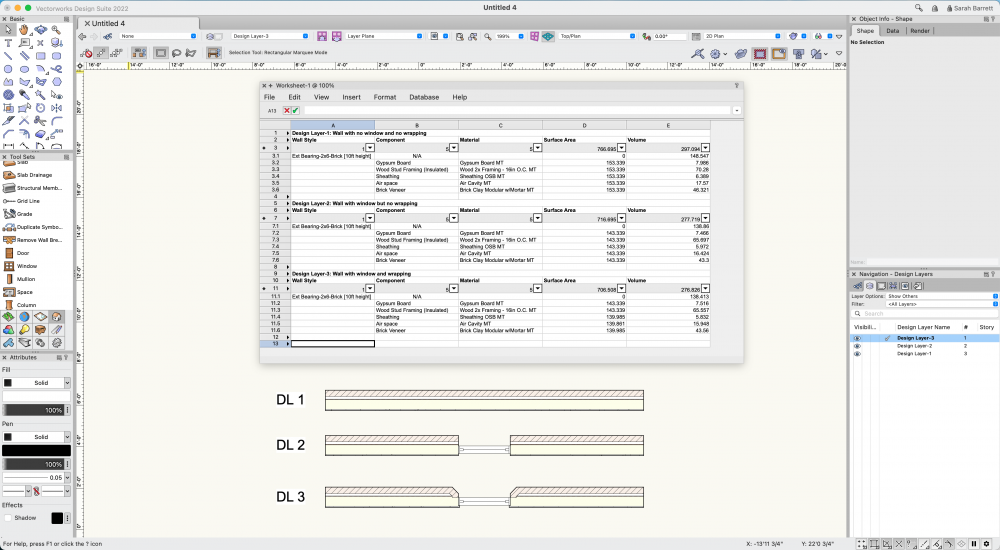
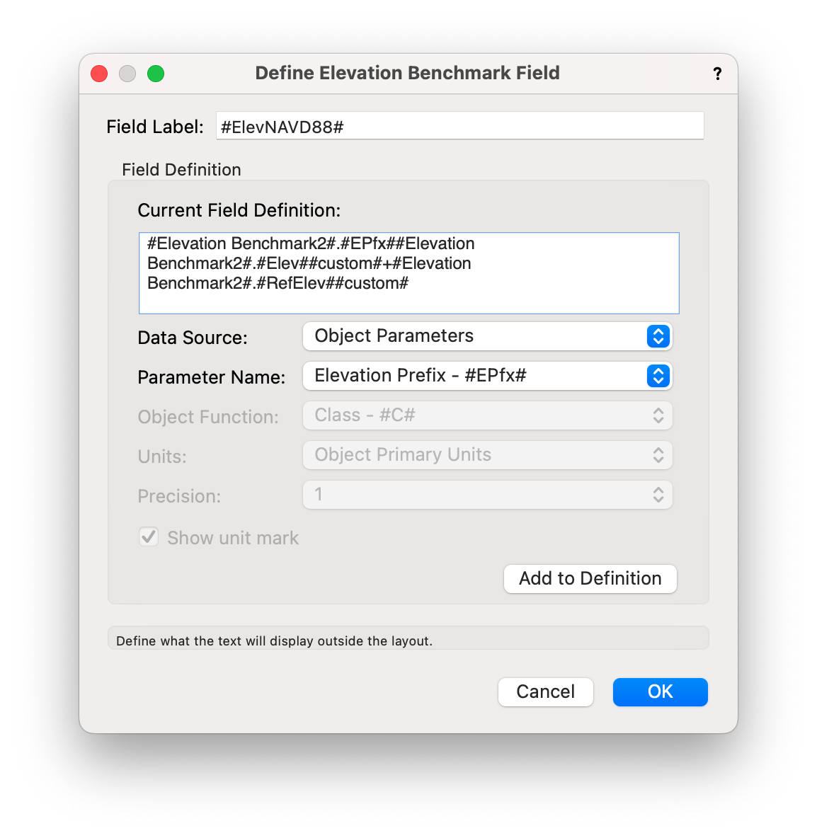
@Tobias Kern yes the volume and surface area of components are updated when they are wrapped. I have attached an image of the same wall in three different states and reported the component quantities in each. You can see that both the surface area and volume change not only when the window is inserted but also when the components are wrapped and splayed at the window.
-
5
-
This sounds like an issue for Tech Support. You can call them directly or fill out a request.
-
I have not tried moving the Keynotes into the annotation space, but they are fine outside the viewport. As far as classing, it is up to you however you want to organize your drawing. Classes are meant as an organization tool for you and your team. If you already have dwgs of manufacturer drawings you can import them into Vectorworks and save them as symbols. You may also be able to download dwgs from the manufacturer website. As far as issues with Notes Manager, I am sorry I don't have any more ideas.
-
1. If you only want the prefix to show up as a Keynote in your drawing, the prefix should not be a part of the note. When you select the note to be placed as a Keynote you can set the appropriate prefix.
2. I believe if you save your document and then restart Vectorworks the last notes database selected will become the active database.
-
I have not heard of iCloud being used in the context of Vectorworks Workgroup Libraries (libraries that are in a location accessible to multiple users) so I would recommend Vectorworks Cloud Services.
-
There is a Notes Manager that allows you to create multiple notes databases. These databases can be saved in a location that is accessible to multiple computers, for example a server or Dropbox or Vectorworks Cloud Services. You can find more info on the Notes Database in Vectorworks Help.
-
1. and 2. Styles are the way to save plug-in object resources. (plug-in objects are anything that is "smart" - has multiple parameters and settings that allow you to customize it). The title block border is plug-in object, as well things like doors and windows. A style will show up in the resource manager as a "red" symbol - the text of the name will be red. A style lives in the file it was created in. If you want to put it somewhere else, you must import it (or drag and drop it) into another file. All resources are stored within files, so your Favorites folder will contain .vwx files with resources. To add a resource to your favorites, either create a new file, import that resource into it, and save that file to your favorites, or if you already have favorites files, import resources into those existing files. I know the system is a little different than AutoCAD, but the most important thing to remember is that resources are ALWAYS stored within files, and in order to have resources available in the Resource Manager, those FILES must be saved in an accessible location like a Favorites Folder.
3. To scale the image within a texture, go to Set by Image in the texture editor and drag the bar to a certain distance along the image and then type in the distance below. For example, if you have a ceramic tile texture, you can align the bar to the length of the tile and type in the length of the tile in the box below. To edit a texture, right-click on it in the Resource Manager and choose Edit. If you like, you can create multiple textures from the same image at different scales - just duplicate and edit the copy.
4. To nest classes, put a hyphen after "Dimension" in each of the names and make sure that you classes are set to be viewed in Hierarchical Display.
5. Activate Titleblock allows it to be calculated in worksheets. Titleblocks should always be activated unless you have so many title blocks that performance is affected. And by many I mean hundreds.
6. To create a template file from a current file, simply delete the geometry in the design layers and then Save As Template. All the classes, layers, sheet layers, and resources will be in the template file when you open it.
-
3
-
-
Dimensions can be associated from any design layer, and also from the annotation space of a viewport. If you are planning to dimension the same object in drawings at multiple scales, I would recommend putting them in the annotation space of a viewport. Otherwise, the same layer in a different class works too. It is really up to you, whatever works best for your workflow.
-
You could do this with Marionette, but I think the easiest way to do this is a lesser known function of the Reshape tool. In the first mode of the Reshape tool, if you use a marquee to select multiple points, you can then drag those and they will stretch.
-
I don't think Get Degree get you any useful info. It is a degree of curvature that is specific to NURBS, so it will be a value of 1 if the point is a sharp angle, 2, or 3, etc. for less sharp angles - it is a value that is specific to NURBS geometry and not a real-world degree value. I believe what you are looking for is the Normal value of a Surface at a certain point. There are NURBS nodes that give you the Normal - the direction of the vector that is normal to the surface at that point. You can use this value to orient objects along a surface, for example. I can't remember the exact name of the node or nodes, but it should have the word Normal in either the name or the output value.
-
You can extract a point anywhere along a NURBS curve and get the Z value, but the point has to be relative to the length of NURBS curve, not the coordinate space. Get degree gives you the curvature of the NURBS curve at that point, I don't think it will get you the Z value.
-
Hello,
This is can be done using several nodes in the default library, you just have to build each little equation separately.

-
1
-
-
Hi @KroVex
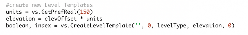
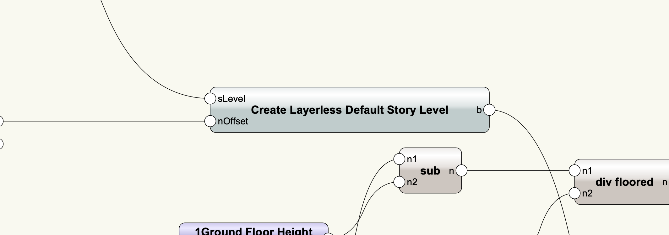
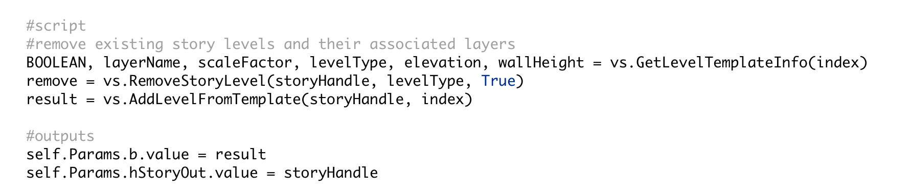
In the script that I created, there are two levels that aren't associated with layers in the stories, and to create those I made a custom node that creates default levels that are not associated with layers and then adds them to each story. I did not associate them with a layer after creation.

This is the script inside the "Create Layerless Default Story Level" node - I simply used a blank string for the layer name.
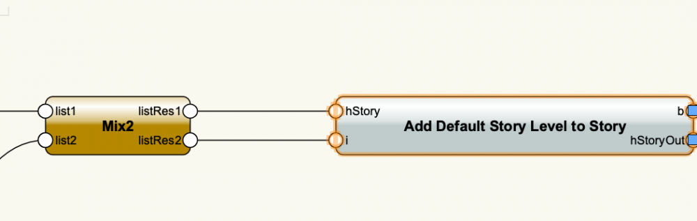
This is the script inside "Add Default Store Level to Story". If the default level does not have a layer name associated with it, it will not create one when added to a story.
-
The sure way I have found to set the stacking order of objects is after they are created, you put them through an ordered list node, put that list through a group node, and then an ungroup node. The group node puts a copy of each object in the group and deletes the original, so the objects are recreated in the appropriate order.
-
1
-
-
I made some changes to the network. Mainly, instead of having the object sent through lots of different Set Record Field nodes at once, I had them pass one through the other. This may not have been necessary but it seems to have fixed the problem. Also, there were a few of the Set Record Field nodes where the Record Name string was not attached. In order to convert this to a menu command and have the fields pop up (instead of being available in the OIP), you can replace the purple Input nodes with User Interaction nodes. There is a User Interaction folder at the bottom of the list of Marionette node folders. These nodes produce dialogs that pop up every time you run a network.
-
No, it is not necessary for the particular network you are creating, but if you want to look for specific types of IFC objects, that is a helpful node. The other thing I did was change the info in the Obj by Criteria node. You can't run a network on selected objects, because a node within the network always has to be selected for the network to be run. The only way to use Marionette on selected objects is to convert the network to a Menu Command. You can do this once the network is complete, but while you are building the network, the Obj by Criteria cannot refer to Selection State.


Add a drawing description to a Viewport?
in Marionette
Posted
In Vectorworks 2024, there are now viewport styles, and with viewport styles you can set the drawing label to be "by style" meaning a particular drawing label style can be added automatically to any viewport of that style.