


ericjhberg
-
Posts
581 -
Joined
-
Last visited
Content Type
Profiles
Forums
Events
Articles
Marionette
Store
Everything posted by ericjhberg
-

Abandoning VW Again...Software needs fundamental changes!
ericjhberg replied to nca777's question in Wishlist - Feature and Content Requests
We have used the Site Model tools and site modifiers/3d polys to a fairly decent extent for coordination. I will admit that here in CA we rely heavily on civil engineers for the final grading documents. That being said, we have found ways of interchanging 3d data with civil engineers to effectively communicate our design intent. If we were drafting our own grading plans and trying to use the site models to draft contours, I think I would be right there with you regarding it's ultimate usefulness. The interpolation it uses seems to always miss the intent and you could spend hours trying to add additional data to smooth it out or get it "close enough". Stay away from the Road Tools is my advice...they're terrible for almost everything to do with roadway design (I have found the NURBS roadway tool useful for vertical grading applications though). Vectorworks has much the same basic drafting capabilities as any CAD software, just organized a little differently, so we draft everything in 2d, "the old fashioned way" with centerlines and offsets, fillets, chamfers, etc and then creating 3d objects from those (i.e. hardscapes, floors, extrudes, etc.). You are correct, the tangent snapping is terrible. We try to keep everything "hybrid" in nature so that it works both in 2d documentation and in 3d documentation as well. Short of a full working knowledge of Civil 3D or MicroStation, I am unsure if any software gets there for roadways...and if you're using either of those, good luck getting anything for plants, irrigation, scheduling, etc. We have found that it's a give and take. There is almost always a way to do something. Whether it is as easy or straightforward as Vectorworks may market or intend is a complete different story. We have found ways to use tools unconventionally to achieve different workaround results, and by doing so, feel very comfortable with our current state of affairs. I think VW has tremendous potential if it is able to counter many of your arguments directly and start working for Landscape Architects and true-BIM. There really isn't another program doing it for our profession, but I see Revit heading in that direction, getting better all the time. With that said, I would hate to see Autodesk also dominate the future market with their industry whitewashing that has frankly ignored Landscape Architecture to date, so I am pulling for VW. -
Abandoning VW Again...Software needs fundamental changes!
ericjhberg replied to nca777's question in Wishlist - Feature and Content Requests
Although I definitely understand your frustration, I can attest that we are a landscape architecture firm performing large-scale development and public works projects and we have been using Vectorworks for some time now to great affect in design documentation (http://www.vectorworks.net/case-studies?id=180). I still find VW better than the alternative and use the many of the imperfect tools you mention, to varying degrees (often just for concept development). There are definitely lots of areas for improvement and I find myself constantly chiming in, trying to make things better. You can view some of the work we do with the software on our website (www.pc-ld.com). I can provide more specific examples if you request. I do agree that the BIM direction is the best thing VW has going for it, but I hope it could find a way to get there a little faster for Landscape Architects, especially in regards to complex document management. It seems that VW has made some strides to better this effort internally. They have hired a couple of landscape architects with lots of previous large-scale expertise to try and guide some of the development in Landmark, which is a bonus. If you are ever interested in some of the more specific workflows we utilize or have specific questions, I'd be happy to chime in. -
Wish list request. I will vote this up!
-
All of the hardscapes in the file are set to be Texture Bed modifiers on the site model. This process worked before in design iteration #1 but now will not.
-
2017 SP3
-
We are having some extreme difficulties with the site model and the use of hardscape>texture bed modifiers. We were updating a site model to reflect some design changes through the method of 3d polys as source data. The site model updates fine if it is not asked to reflect hardscape>texture bed modifiers in a different layer, but once the site model tries to update with those modifiers, it just won't work. The problem is that it worked before. We wouldn't have invested this much time if it didn't work the first time and now we are stuck, unable to update the 3d of our design. I have attached the file. Try and update the site model to reflect the hardscape>texture bed modifiers. 333_Site model.vwx
-
When using the stake tool, you currently have the option to "Set Elev to Site Model" as a way of creating spot elevations for a grading plan. This is great when documenting the surface of a site model for high points and such, but often the elevation we are looking to document is actually a feature such as finish surface, top of wall, bottom of wall, etc. These items are placed on top of a site model, so a stake object trying to query their top elevation will only return the elevation of the underlying site model. There should be a way for the stake tool to recognize modeled elements in the drawing to pull this information into its reference.
- 21 replies
-
- 12
-

-
- site model
- grading
- (and 2 more)
-
I wish that the drawing name automatically equaled the viewport name for sheet layer viewports. Either that or get rid of one of the naming categories .I don't understand why we need two different names for a viewport. This would streamline visibility controls, reduce redundancy, and help with using drawings labels.
-
Paragraph Editing
ericjhberg replied to binubinu's question in Wishlist - Feature and Content Requests
Agreed! -
Paragraph Editing
ericjhberg replied to binubinu's question in Wishlist - Feature and Content Requests
What could be even better is some function, similar to Adobe InDesign, that would allow you to insert referenced text and formatting from a Word Doc. That way you could do all of your text editing and writing for certain elements in Word where you get the benefit of Auto Spell Check and Auto Grammar Check, as well as auto-numbering and auto-bulleting. -
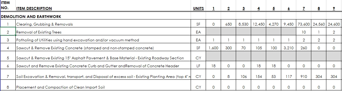
We are often tasked with quantifying elements in our drawings and dividing these quantities up along different sections of the design. To provide an example, the following screenshot shows an excel spreadsheet being used to track quantities across 9 medians in this case. Each row is a separate line item that we need to provide quantities for and each column to the right, a separate median. Also note that each row is potentially a different unit. It would be great if Vectorworks' worksheets had the capability to do something similar using database headers. I know it is possible by writing individual formulas in cells of a spreadsheet, but that gets cumbersome and potentially creates errors as classes modify and things shift throughout a project. Its a lot to keep track of. I also know that this could be managed by a record with separate fields for each of the medians' quantities, but again, that would have to updated each time the drawing shape changes since there is no way to link a shapes properties (i.e. area, volume, length, etc.) to a record value. We can easily separate quantities using design layers, polygon location references, records, etc, so what I am imagining is a general database header formula...L='Demo' in this example. Then in columns I could use the =C formula to summarize rows based on classes (essentially the line items from the example) above, Use the formula =AREA(LOC='MEDIAN 1'), =AREA(LOC='MEDIAN 2'), =AREA(LOC='MEDIAN 3'), etc. for all of the columns calculating quantities. I don't really have a great way of separating the units (=area, =length, =volume, etc.) though, so I would have to create a database header for each different quantity (which can screw up the order)
-
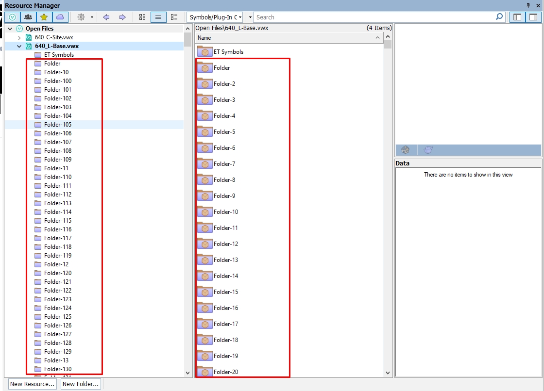
When using the Existing Tree tool, somehow empty folders are created in the resource manager. Every edit, move, copy, tweak, etc. in an existing tree tool results in the creation of an empty resource manager folder. I am currently working on a project with 150+ existing tree tools and this resulted in the creation of over 200 empty folders?
-
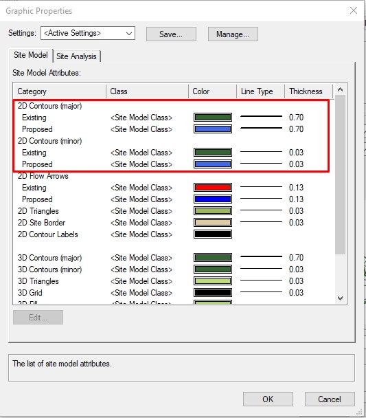
In the most basic form, this is exactly what Site Models can do. Site models have both an existing version and a proposed version, allowing for direct comparison and even the calculation of cut/fill. The workflow is: Create site model from Existing 3D Data Create site modifiers that work on the "Proposed" site model (not the "Existing") Make sure your 2d visualization settings for the site model are set to "Proposed + Existing" In the Site Model's "Graphic Properties..." settings, you can assign different visual attributes to 2D Contours (see below) This of course is a very simplified workflow. We have found that creating detailed and accurate site models is a very time consuming process with many Best Practices.
-
You could put the building on its own design layer and set the design layer settings to have an elevation associated with the pad or finished floor elevation for your building.
-
2D vs 3D vs BIM - Where are we going?
ericjhberg replied to ericjhberg's topic in General Discussion
Now that's pretty cool. The interface seems a little difficult for something as complex as a site plan or building, but definitely an interested step in the right direction. -
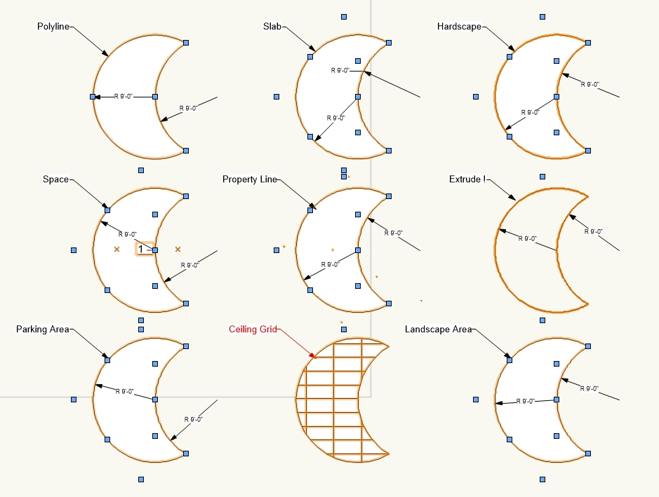
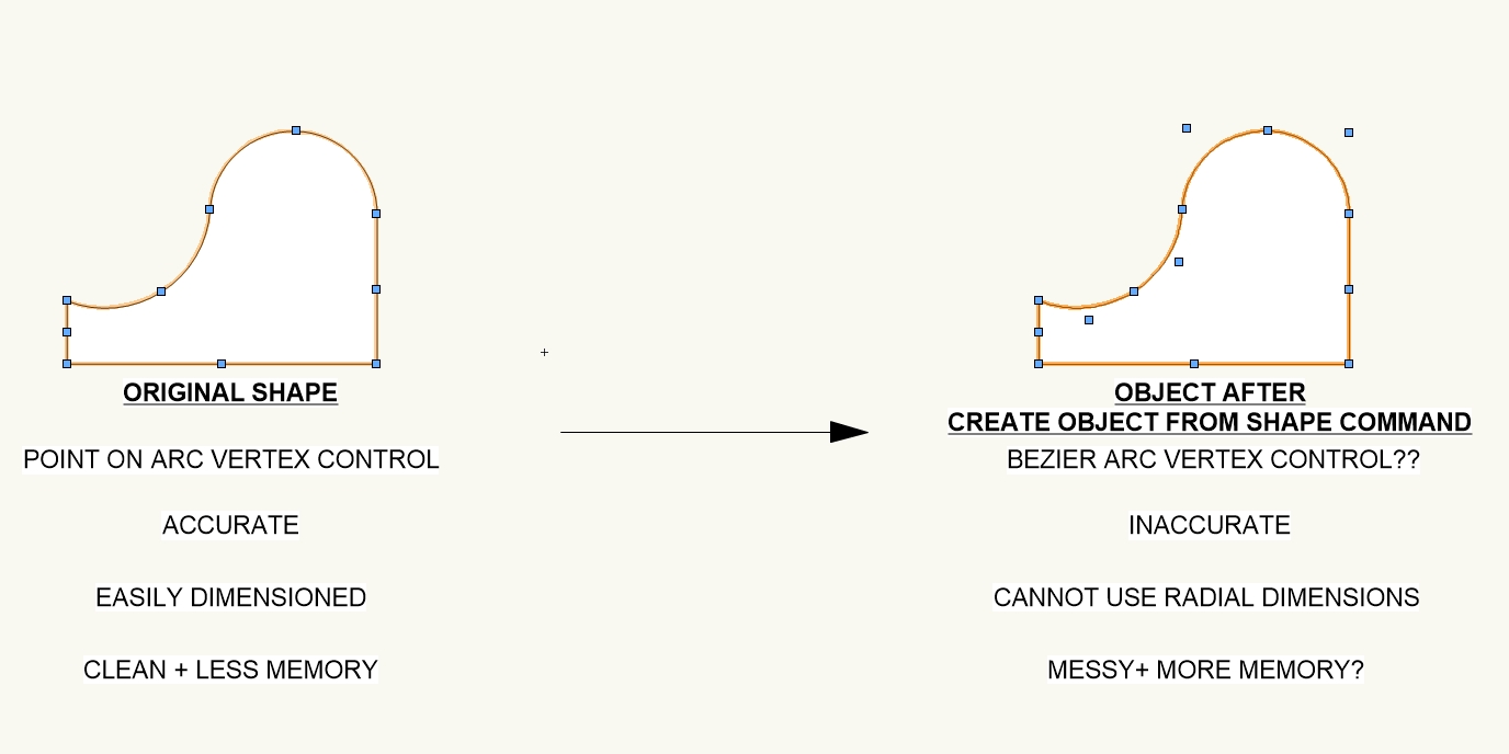
Ah yes, you now have 5 arcs instead of 2. That means the shape is much harder to accurately modify than originally intended. Because of this we encounter "slivers" often where the arc of two adjacent hardscapes interpolates differently and leaves a tiny gap in between. Plus, if I needed to modify a hardscape object's arc after this interpolation happens, I no longer have one point on arc vertex to alter, I have the bezier handles...and I don't even know where to start with those. Why can't 2 arcs = 2 arcs rather than 2 arcs = 5 arcs?...no thanks...added complexity, memory, room for error.
-
When pipes are created, they cannot be offset by conventional methods. I understand that this request is more complex considering the network character of irrigation pipes, but for graphic clarity on irrigation plans, this is often a must! Sometimes there is a need to convey that several pipes are running along side each other. The cleanest way of doing this is by an offset. To get around this, we have started by creating our pipes using polylines, and offsetting as necessary before Create Objects from Shapes... into pipes (see this post for my separate issue with this command). This works fine until we have to add another pipe or change something and the original functionality is lost.
-
Irrigation - Pipe Jump Autosize
ericjhberg posted a question in Wishlist - Feature and Content Requests
When using the new irrigation pipe tool, crossing pipes is automatically controlled by an auto-jump feature. The problem is that it automatically creates a gigantic jump. We are very particular graphically. Before the creation of the irrigation tools we precisely created 9" radiused pipe jumps everywhere (depending on graphic scale that dimension can occasionally change). Can we integrate the ability to provide a setting for auto-pipe-jumps to be a specific radius first, and then if we have to change it manually we can? The current process is very time consuming and not at all precise. We have to manually scale every pipe jump and there are no dimensional settings, meaning every single one is slightly different.- 8 replies
-
- 1
-
-
- irrigation
- pipe
- (and 1 more)
-
Yes SP3. Try to edit the vertices of any of the Convert to Objects... shapes. You will see that the original point on arc control is destroyed in the creation of the shapes, with the exception of the extrude and the ceiling grid. This is where the problem lies...the destruction of precise geometry.
-
Interesting. I'm not so much worried about the ability to dimension as I am what the dimension is measuring. If the original intent of the arc is compromised by the Create Shapes from Objects... command as shown above, then this creates room for error. Granted it isn't much error, but I am a big proponent of drafting accuracy and this phenomena flies in the face of that. Throughout a project, these errors, and the inability to efficiently fix them, add up and can wreak havoc.
-
Another one of those, try, try again until you succeed posts. I posted this awhile ago and included a video, to no avail or answer yet. When using the new irrigation tools, once a pipe is drawn and components are added to it, there is no way to rotate the graphic symbol other than to a true north. What is interesting is that the OIP will show a rotation angle even though the graphic symbol doesn't rotate. You can see the video for a better explanation (sorry, no voice over). https://screencast-o-matic.com/watch/cDX33GQh5g This is really annoying because we almost never get so lucky to work in a true north orientation and our best practice has always been to relate system components and their rotation to the line on which they are placed. It just adds graphic clarity. This problem is also true of any tags or labels that are created from an irrigation object. They cannot be rotated so as to appear horizontal on a sheet layer viewport. This is common practice and I don't understand why the usability hasn't been integrated. We have largely avoided the entire irrigation suite, and this problem is a large reason why. Fix please!
-
I have asked this question before and don't know if I ever got a response. so why not try again. When using the CREATE OBJECTS FROM SHAPES... command to convert any basic object into something else (doesn't matter what), there is a conversion of any accurately drafted arc and radius information from a point on arc mode to a bezier mode. See the attached image for comparison. This is a frustrating phenomena/bug for the many reasons noted, but most importantly for the loss in fidelity. Once an original object is converted, there is no way to restore the original arc fidelity. I have requested a fix for this before and feel that this should be dealt with ASAP.
-
I've mentioned this in other posts...just mirroring the hierarchical functionality of classes with layers would help tremendously. I can't speak to the benefits of adding search capabilities because that would also be cumbersome. Finding a way to pair down the list into categories, folders, types, etc. would be a huge step in getting us to that 1 project, 1 file ideal. Without it, I won't even attempt project sharing or anything remotely related. Good clean organization will set you free!
-
I'm interested too. I've wishlisted a better layer organization/hierarchy strategy to help us get to the 1 project, 1 file solution, but until then, I cannot imagine trying to coordinate a team when files could contain 100s of design layers to navigate through...gives me a headache just thinking about it.
-
2D vs 3D vs BIM - Where are we going?
ericjhberg replied to ericjhberg's topic in General Discussion
Interesting? Though this is not my experience here in California, it is nice to hear that some people are starting to experience the benefits of this "revolutionary change". Is anyone dealing with this in the States? I agree with all the benefits, and to the extent that we consider ourselves a "cutting-edge" firm, we definitely get caught up, from time to time, in the old ways.