


line-weight
-
Posts
3,755 -
Joined
-
Last visited
Content Type
Profiles
Forums
Events
Articles
Marionette
Store
Posts posted by line-weight
-
-
I think you'll find that you come up against various things that aren't possible with this tool. It'll let you customise up to a point and not further. And there are some things that you could do with the old version, that you now can't. For example L-shaped corner cabinet with unequal leg lengths.
-
 1
1
-
-
Although you can make it as @Pat Stanford says, I think you might then have troubles making it join with the horizontal overhanging roof element that you want it to be continuous with.
-
1
-
-
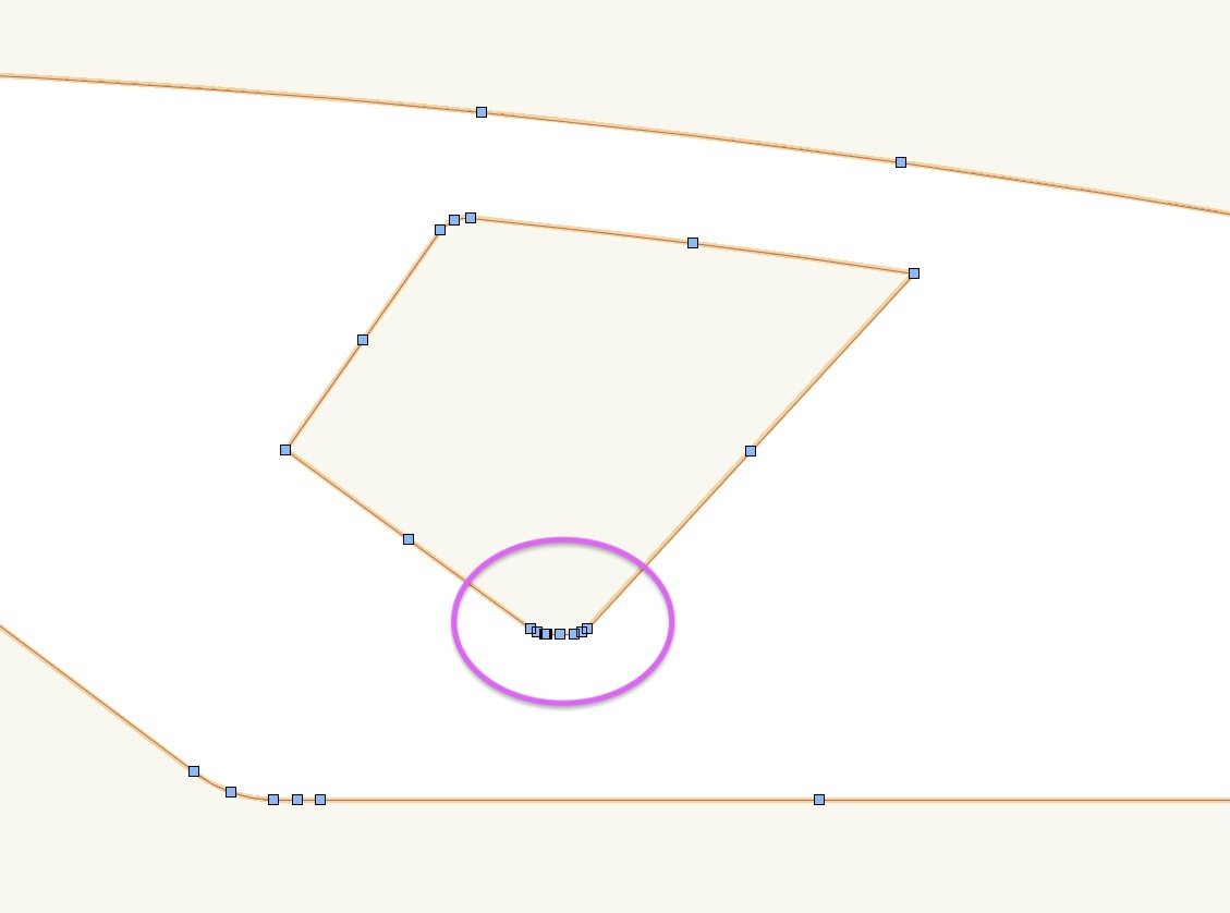
Yup there's something whacky going on here:
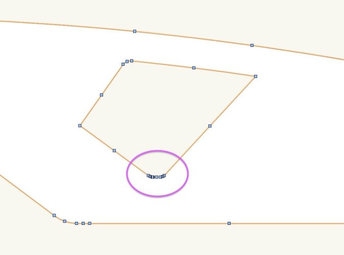
I zoomed right in and deleted some errant vertices, and then it seemed to be fine.
-
1
-
-
I feel that I sometimes experience this too. Snaps & their cues stop working and things return to normal when I re-start VW.
-
2
-
-
2 hours ago, Pat Stanford said:
I dont' use Stories or Levels. Can those of you who do please comment on if there is any benefit to using them if you are not using Walls and PIOs that can automatically associate with the levels?
If I am only using modeled solids that won't automatically adjust when I change levels is there any benefit for me?
As l said above, the ability to use elevation benchmarks is benefit enough for me. Even if no objects are actually associated with them.
I no longer need to have the bit of paper stuck next to the screen with a project's significant levels written on it.
Part of the attraction for me is that I don't really like giving layers elevations, because I like to be able to paste-in-place between different building storeys. Having a single storey with a number of important/useful "levels" proves to be a good way of keeping Z values organised and recorded. For me and the kind of projects I do.
I find it quite satisfying/reassuring when I can make, say, a steelwork setting-out drawing and with a couple of clicks have things like finished floor levels, or top-of-steel levels, or whatever appear in the right locations in viewports.
-
4
-
-
I think it's because you've got "display 2D components" turned on. So it is drawing the 2d component of the symbol rather than rendering directly from its 3d geometry.
To make it coloured you either need to turn off "display 2D components, or edit the symbol's 2d component so that it has the colours you want.
-
5 hours ago, E|FA said:
If you're doing that why use Stories at all? Take a look at the original post in this thread to see the No Story workflow.
Like Zoomer says, it's mainly about accessing Levels.
The parametric possibilities are one reason, but also the ability to have reference levels that I can use to create elevation benchmarks on elevations/section viewports. Even if I never really change the levels, I find them very useful for making sure everything is in the right place. It's a visual check that things are at the correct height relative to things like finished floor levels, and is also useful when I have "existing" vs "proposed" and need to match a height somewhere. I like that the elevation benchmarks will always be correct automatically. Similar to grid lines in plan views.
-
4
-
-
Do you have "use original" selected here?
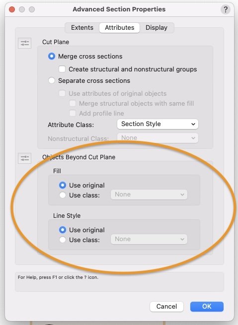
That controls what any objects seen in elevation will look like.
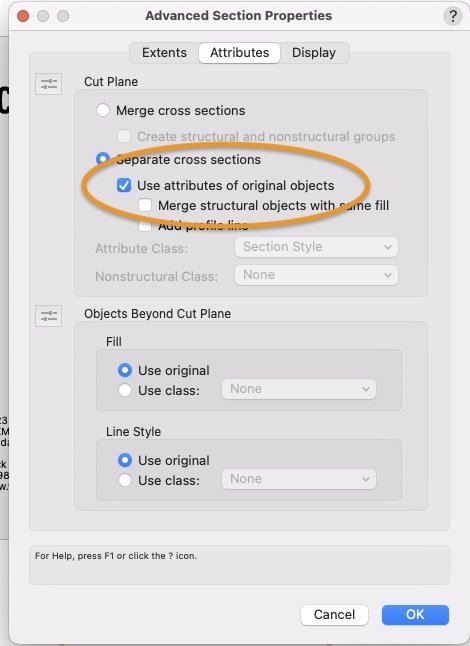
If you also want the objects to retain their colours where they are sectioned, you'll need to select this too:
-
Is it a building with multiple levels, and are those multiple levels repetitive?
If not, just put everything in one storey. Then you don't need to worry about storey elevations. Just have a zero datum for the whole thing & relate all your levels to that.
-
1
-
-
13 hours ago, Bruce Kieffer said:
Look back at the original post. I explained the need there.
Sorry, my question was aimed at @Mickey.
-
I don't really understand what you're trying to achieve. I'm not quite sure how a section of a wireframe would really be meaningful or useful. Can you post something that lets us see what you're trying to show?
-
There's something wrong with the way this works. It often seems impossible to find the legend that's supposedly been created (even using the custom search).
I have to resort to copy-pasting one in from another file, and then all new ones in that file are made by duplicating the first one.
-
Ah right I see. Yes, I can't see a way of doing that either.
-
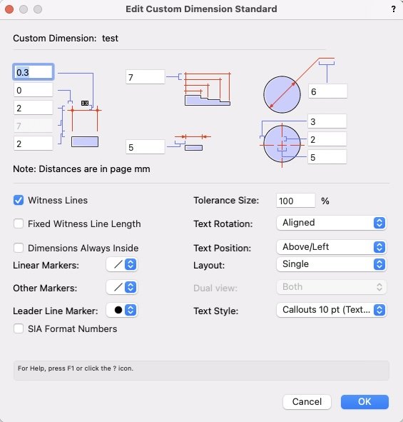
You can do - with pointer tool active and the dimension selcted, hover over the text block, then it lets you grab it and move it anywhere you want.
Or do you mean have it align in a certain way by default? There are quite a few things you can adjust in dimension standards -
-
I've never noticed that option either.
-
2 hours ago, MarcelP102 said:
Nice model. Only the window above the door seems different on the picture and missing the horizontal line. 🫢😉
The temptation to make a list of all the things that aren't quite correct is hard to resist for me, who gets really obsessed about getting surveys right and spends way more time chasing accuracy than makes any business sense...
-
3
-
-
25 minutes ago, Tom W. said:
I actually did this recently but found that I couldn’t turn off the second leaf in my Graphic Legend for summer reason. In fact I have encountered this elsewhere with Hidden Line viewports: I have had symbols containing two different states for the same object, separated by class, but in HL both classes remain visible regardless of the class visibility settings. In Shaded the visibilities work as expected but not in HL. I have had to separate the two different states into two different symbols + control the visibility of the symbols in order to get the VP to display properly. Don’t think I’ve seen this reported elsewhere but it has definitely happened to me several times, including like I say a few days ago with a custom door symbol. I had to delete the open leaf geometry from the symbol in order for the GL to display correctly…Hm. I don't think that's happened to me (yet).
I wonder if it's a symbol-inside-a-symbol problem?
In many cases, my custom doors/windows are actually groups rather than symbols (so the door leafs are symbols within a group).
-
It's quite easy to achieve this if you build your own door objects. Make the door leaf a symbol, duplicate it and rotate one copy 90 degrees. Make two classes, one "doors open" and one "doors closed" and put the instances of the door leaf in each. Then you can choose per viewport which of those classes you want visible and hence whether the doors are open or closed. If you want you can make it more fine grained and control it per door.
This of course is not very helpful if you need/want to use VW door objects. However, it makes it feel like it shouldn't be all that difficult to implement for VW doors.
-
1
-
-
14 hours ago, AHiguera said:
This is arguably a bug. It seems what the push/pull tool is doing is creating a solid addition out of the original extrude and some additional geometry. If I ungroup the solid addition, the original extrude remains marked as "Ignore Closure".I guess that's in "extrude face" mode of the push/pull tool. In "move face mode" the object is immediately converted to a generic solid with no history and loses its status at that point.
-
- Popular Post
- Popular Post
I guess I'm not the only one who just closes this window immediately when starting up VW.
One of the reasons is that the list of recent files is not ordered in a useful way. It lists them according to when they were last opened. This means that if I've had a main project file open for a few days, but have a opened and closed a bunch of other unimportant things in the meantime, the main project file appears somewhere well down the list. So I have to go searching for it. It doesn't give me any advantage over just using "open recent" in the file menu. At least there the list is more compact and I don't have to scroll down to see the bottom of it.
If it listed files according to "last closed" for example, this would be more useful.
-
5
-
So, now to the sill. Again this drawing is produced without any additions/alterations in the annotation space. It basically gets everything where I want it.
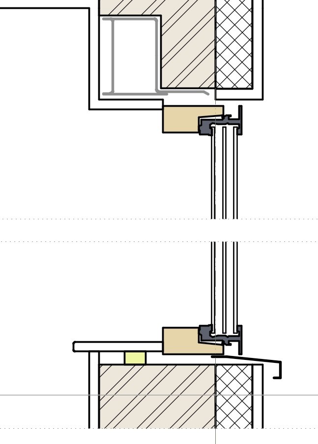
No components need to wrap into the opening at the cill. However, the internal plaster layer needs to oversail the other wall components and continue up to the underside of the interior sill.
This is where it's a bit frustrating that we can't simply specify an "offset" per component. I've achieved what I want by adjusting the shape of the symbol's wall hole component and this works - but if for example I were to change the wall buildup slightly, so that the brickwork layer had a different thickness, or if I wanted to move the window inwards or outwards a bit, I'd have to go and edit the wall hole component manually too.
I have fiddled around a bit with the "profile offsets" and "wrapping" settings for the bottom of the window opening to see if I can get it to produce what I want (that inner plaster layer oversailing the other wall components) but as far as I can see, this isn't possible. Am I missing something?
-
Callouts really are a pain. For years I had the habit of hardly ever inserting them "fresh", instead copy-pasting from somewhere else, because it was easier than pinning down exactly what controls their attributes.
They also have a confusing behaviour in the way they exist in page/world units. I think you can set defaults in page units but then they convert to world units when you place them - something like that. And copying them between viewports of different scales messes them up.
-
2
-
-
47 minutes ago, Tom W. said:
So the window symbol is clipping the hole in the wall for the lintel + the lintel itself is just a manually placed 3D object?
I'm just interested. I have done things similar where the lintel is a symbol inserted in the wall with its own wall hole component but then it gets complex with the wall closures because you're dealing with two objects (the window + the lintel)
Yes, just as you describe, I've got the lintel as an independent object just placed into the relevant location. But you're right, it could be part of the window symbol and there's a good argument to do that. Would make it easier to move the window position for example.
-
50 minutes ago, Tom W. said:
So is the steel lintel part of the window symbol?
It's not...but I guess it could be.
2024 - Fence Tool Improvements
in News You Need
Posted
These yuk responses, which of course must be disheartening for the VW employees who put so much hard work into developing these complex tools, could be avoided if the company were to take user testing and interface design seriously, but it's very clear that the people at the top don't. The proof of the pudding is in the eating.