


line-weight
-
Posts
3,755 -
Joined
-
Last visited
Content Type
Profiles
Forums
Events
Articles
Marionette
Store
Everything posted by line-weight
-
@DiggleDesigns my advice would be don't waste any of your life trying to animate things in Vectorworks. That includes the built in tool for creating walkthrough animations - it's truly awful. Even the spin/orbit type animations are horrible - it's very difficult to get smooth animation without lurching and jerking. The two examples posted above demonstrate this. There are a few threads detailing the many bugs and shortcomings of the animation tool, and no sign that there is any interest in fixing them.
-
 yes, exactly.
 -
A little round-up of my experiment doing bug submits & help page feedback as we are requested to do. 1) Bug submit done on 20th January - took about 12 minutes of my time. I wrote out description & provided sample video - prior to that I had started a thread on the issue here in the forums - no immediate confirmation email - got a response by email 5 days later confirming it had been replicated & would be looked into - some time later, acknowledged in the forum thread by VW employee - it was fixed in the next release 2) Bug submit done on 16th February - took 5-10 minutes of my time. - I simply gave a link to a thread on the forums where the problem was already described & discussed in detail. - no immediate confirmation email - as of now, 2 months later no email response - no response from any VW employees on the relevant forum thread 3) "Help" pages feedback submitted via webform 28th January - took about 10 minutes of my time - no immediate confirmation email - email reponse a few days later, saying my feedback would be incorporated into an update to the help page - help page was updated 4) Another "Help" pages feedback submitted via webform 28th January - took about 10 minutes of my time - no immediate confirmation email - no response of any kind 2.5 months later - no changes made to help pages so far. So, that's a 50% success rate. That's certainly better than nothing, and I appreciate the items that were responded to. However, I'm not sure it's a better success rate than nagging about things on the forums. So I don't feel to encouraged to carry on with my experiment of doing things the "proper" way.
-
How to select objects by hovering over face
line-weight replied to oliver.williams's topic in Solids Modeling
I have no idea! either as some kind of workaround due to some kind of problem some years in the past now forgotten ... or I just unticked those boxes accidentally at some point. -
How to select objects by hovering over face
line-weight replied to oliver.williams's topic in Solids Modeling
yes, I realised that I have (for some reason) "enable cursor pre-selection highlighting" turned off in my VW preferences, which is why I am not used to seeing it.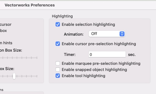
-
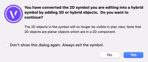
Well, the one use case where I've been thinking, I can definitely use graphic legends for that, is the next time I'm doing an electrical layout plan. And yes, I generally make these as 2d-only symbols. So it does seem rather strange that these would be excluded. I always have a background anxiety about symbols anyway, because I am never quite sure if 2d symbols are a fundamentally different thing to hybrid symbols (rather than just the same thing but without a blank 3d component) and vice versa. And each time I get this message I look at it for a while and start to get a headache. I think it's talking about plan view, not top/plan view, is it? I'd rather we just had one type of symbol: with a 2d and 3d component, either of which can simply be empty/blank. The 2d component appears in top/plan or annotations space, the 3d components appear in any view that's a projection of 3d geometry. That's unless it's something like a horizontal section viewport where there are controls to choose one or the other.
-
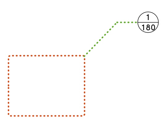
Detail callout markers (DCMs) have three basic parts - The bit I've made red above, which I'll call the "crop box". The line colour, type, thickness and fill of this are controlled per instance, by changing the object's attributes in the attributes panel. If the DCM is given a certain class, then the attributes of this "crop box" can be set to be by class. The shape of this crop box is essentially drawn per instance. - The bit I've made green which VW calls the "leader (and shoulder?)". The attributes of this line can be controlled per instance using the DCM's OIP, or they can be controlled by a DCM style. - The bit I've made black I'll call the "marker" and the layout and appearance of this can be controlled by style What I'd like: 1) The attributes, and basic shape of the "crop box" should be included in the things that can be controlled by style. Why would I want to control the leader & shoulder by style, but not the crop box? It doesn't make sense. At the moment, to get a reasonably consistent appearance for all of these objects I have to do it using a special class. 2) If "rounded rectangle" is to be one of the shapes we can use for the crop box, then the radius of the corner fillets needs to be independent of the scale of the viewport I'm using it on. That is, whatever value I give for the fillet radius needs to produce the same result whether I'm using it on a 1:100 or 1:2 scale sheet layer viewport. I see no reason why it is useful to have it relative to the scale of the viewport. 3) If "rounded rectangle" is to be one of the shapes we can use, and especially if it's not included in the things we can control by style, then there needs to be an easy way of retrospectively changing the radius of those corner fillets. At the moment it's unintuitive and convoluted, and involves changing each vertex individually using the "change vertex mode" of the reshape tool.
- 3 replies
-
- 12
-

-
- detail callout
- style
- (and 1 more)
-
Can I "unlink" a Section-Elevation line?
line-weight replied to line-weight's topic in General Discussion
Actually they all live on a special viewport on a dedicated sheet layer that I use only to control the cut planes of my sections. And there they are just "style whatever" because I don't care what they look like as they never appear on a published drawing. So I guess they are Style A and if I changed them all to Style B, then I'd get the behaviour I want? It seems a bit strange that every instance of a section line on any viewport has to be the same style ... I'd have thought you might want to choose the style per viewport. But anyway, I think this answers my question. -
Can I "unlink" a Section-Elevation line?
line-weight replied to line-weight's topic in General Discussion
I have section viewports 1, 2 and 3. Then I have plan viewports: ground floor plan, first floor plan On the ground floor plan viewport, I want instances of section lines 1, 2 and 3. On the first floor plan viepwort, I want instances of section lines 1, 2, and 3 I have section line style A (some sort of VW default one) and section line style B (my own one). The section line tool I've set up in the preferences to use section line style B and that works fine if I just use the tool to manually draw a section line (unlinked and undefining). But what I want to do, is go to section viewport 1, press the "section line instances" button in its OIP, then in the list of viewports I'm offered, put a tick against "ground floor plan" and "first floor plan". When I do this, and then go to look at "ground floor plan" or "first floor plan", section line 1 has appeared in both of them as expected. However the section line that appears has section line style A (and I want section line style B). -
Can I "unlink" a Section-Elevation line?
line-weight replied to line-weight's topic in General Discussion
Incidentally, when I add a section-elevation line to a viewport, by choosing that viewport in the "section line instances" of the section viewport that it links to/defines, I seem to get a section line in a default style, not my own style which I have set up. That's despite having my own style set as the one to use in the section-elevation line tool preferences. Is there some way that my own style can automatically be used when I create a section line using this method? -
Can I "unlink" a Section-Elevation line?
line-weight replied to line-weight's topic in General Discussion
Since this was last discussed, 2 years ago, I've started using the grid tool and elevation benchmarks, both of which allow the elements to be resized per viewport, so it does feel out of step that section-elevation lines don't offer something similar. -
Why aren't my slab component offsets working?
line-weight replied to line-weight's question in Troubleshooting
Good call - it works if I have "enable tool highlighting" active - which I previously didn't. -
Can I "unlink" a Section-Elevation line?
line-weight replied to line-weight's topic in General Discussion
@Matt Panzer did this enhancement request get anywhere yet? The way section-elevation lines currently behave significantly limits their potential usefulness. -
How to select objects by hovering over face
line-weight replied to oliver.williams's topic in Solids Modeling
What exactly do you mean by "highlight"? Do you mean that the cursor changes from an arrow with tail to an arrowhead without tail? Or something else? -
Why aren't my slab component offsets working?
line-weight replied to line-weight's question in Troubleshooting
@Matt Panzer separate from the main discussion here: do you have any clues why, when I use the per-instance "edge offsets" dialogue, I am not seeing the edges highlighted in red as they are supposed to be? -
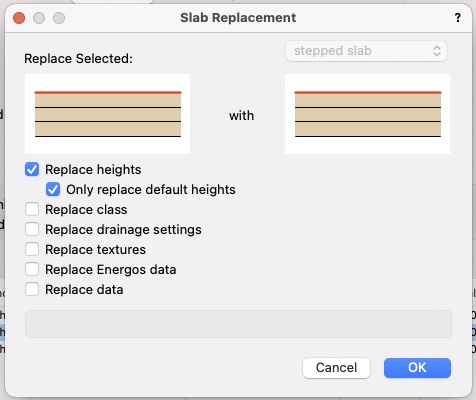
If you edit a slab style, and change the edge offset of any components, these changes don't get applied to any existing slabs with that style. The option of whether they get applied to existing slabs needs to be offered to the user and I'd suggest the place for this to happen is in the "slab replacement" dialogue. More detailed discussion here:
-
Why aren't my slab component offsets working?
line-weight replied to line-weight's question in Troubleshooting
I very frequently edit wall styles as a way of making an update to many walls that already exist in a drawing. From my point of view, an edit to a wall style almost always has the purpose of making changes to a bunch of already existing walls. If I want to make some new walls with slightly different parameters, I make a new wall style. The same applies to slabs and roof faces. At an early stage of a drawing I might have basic wall, slab or roof face style that just estimates an overall thickness. Then later, I'll add detail to those styles by adding specific components representing specific materials and so on. The "wall replacement" dialogue is part of the mechanism that allows me to choose what is or isn't going to be propagated to existing wall instances. That's fine, because I know what's happening and am alerted to the things where this is a choice. There's also a "slab replacement dialogue" This is where I choose what's going to happen to existing instances. I think if certain style parameters (edge offsets) aren't shown here, it's reasonable to assume that they behave like any other styled parameter - they will be applied to existing instances. It's also what the documentation leads me to expect: https://app-help.vectorworks.net/2023/eng/VW2023_Guide/Floors_slabs/Editing_slab_styles.htm#h But of course that's not what happens, hence this thread. I'll do a wishlist item though.

-
Why aren't my slab component offsets working?
line-weight replied to line-weight's question in Troubleshooting
I agree the implementation is different, but the concept is the same (or at least, I think it should be). When I edit a wall style, I don't get a panel of settings each of which I can toggle between "by style" and "by instance". Instead I get a panel of settings all of which apply style-wide, and I think it's reasonably clear that they do. I don't really get to choose whether certain things are per instance or per style, but generally I'm pretty certain, when I adjust something, whether it's just going to apply to that instance, or whether I'm adjusting the style itself. And if I adjust the style I expect that change to propagate to all instances. What appears to be the approach with slab styles muddies the waters, because I edit the style but am not told that this is not going to propagate to already existing instances. I've been trained to expect a certain behaviour, and now something different happens. To quote the Vectorworks documentation (my bold): In my view we are trained to expect that if we change something in a style, it changes in all instances of that style. That applies regardless of whether we're dealing with a PIO or things like Walls. I don't think it's good to have exceptions where a change in style only affects instances subsequently created in that style. Where that's the intended behaviour there should be a different mechanism to allow it. -
Why aren't my slab component offsets working?
line-weight replied to line-weight's question in Troubleshooting
That would make sense for edge offsets that have been manually over-ridden using the dedicated dialogue. But not for offsets that are specifically set "per style". This is another example of abusing concepts that users expect to be consistent and predictable. If I set something to be by style, then it should be by style. And it should behave like any other thing that is set by style: edit the style and all the instances change. This is the whole point of styles. -
Why aren't my slab component offsets working?
line-weight replied to line-weight's question in Troubleshooting
I had a quick look in VW2021 and it seems that the same (or nearly the same) happens there. If it's a bug it's strange it's not been noticed before, or is this an indication of how few people actually use these component offsets within slabs? -
Why aren't my slab component offsets working?
line-weight replied to line-weight's question in Troubleshooting
Didn't initially understand what you meant by this but then realised you mean selected within the slab tool. I get the same result. However, edits to the style's offset settings still aren't updated to the object. -
Why aren't my slab component offsets working?
line-weight replied to line-weight's question in Troubleshooting
And here are the edges failing to highlight in red when I try the manual over-ride process: Screen Recording 2023-04-04 at 14.42.14.mov -
Why aren't my slab component offsets working?
line-weight replied to line-weight's question in Troubleshooting
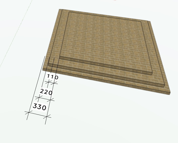
Attached is another file. It should look like this on opening: Some steps if anyone wants to try replicating: 1) Convert that white square to a slab. 2) Apply the "stepped slab" (already in the file) style to it. I get this result: Note that the top component is not offset by 110 as it should be. 3) Edit the "stepped slab" style, so that component 3 has an offset of 500 instead of 330. When I do this, nothing changes. Nothing changes on the L-shaped slab either. This has had the "stepped slab" applied to it all along, but takes on no offsets at all. slaboffsets2.vwx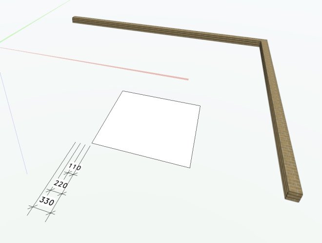
-
Why aren't my slab component offsets working?
line-weight replied to line-weight's question in Troubleshooting
Ok... if I make my slab settings into a style and then apply that style to a newly created slab, I get the stepped arrangement as expected* But if I then edit the style, changing the offset of one of the components, nothing changes. If I convert the slab to an "unstyled" one and again edit the offsets, nothing changes. -
Why aren't my slab component offsets working?
line-weight replied to line-weight's question in Troubleshooting
Don't think so. Drawn in polygon mode. I may have used "reshape" on it since - not quite sure. But without going into that "edge offsets" dialogue - shouldn't each component layer be offsetting itself as I've set up, or am I misunderstanding how it's supposed to work? I've attached a file. slaboffsets.vwx
