


line-weight
-
Posts
3,754 -
Joined
-
Last visited
Content Type
Profiles
Forums
Events
Articles
Marionette
Store
Posts posted by line-weight
-
-
1 minute ago, Mark Aceto said:
The 2D geometry is ostensibly a hidden line render, so if I want to see a hidden line render of a 3D view, I’ll just render that VP in hidden line. I don’t have a use case where I will mix a few hidden line rendered objects in a wireframe elevation view.The same thing happens with Schematic Views when using Braceworks / truss workflows or any vertical structural member that can’t be tipped up from a laying flat position (truss tower, goalpost, torm). The end result is just another hidden line elevation view, so there’s really no point in creating extra work my myself.
That said, if I’m missing the utility of this feature beyond bathroom fixtures LOD, someone please post a screenshot of how you use it.
Do you work in a lighting/entertainment rather than architectural context?
I'm not familiar with braceworks and I don't know what a "Schematic View" is.
But for many of us working on architectural drawings, hidden line sections are rather crucial.
I don't actually use those 2d components as much as I could - but intend to start using them a bit more. And if you want to customise them at all, then flipping between these different components (and being able to see the 3d component geometry in the background) is rather useful.
-
 1
1
-
-
38 minutes ago, Mark Aceto said:
Every other (3D) view is just a hidden line view that will render in hidden line anyway.
I don't understand what you mean here.
-
I find it a little annoying that it floats around and would probably prefer it to be somehow "docked" but I find it useful while working on symbols.
Recently I have been using it quite a bit flipping between 3d component/wall hole component/wall closure component.
That process could be smoother (often the view position seems to jump when moving between these components) but that's a separate issue.
One thing I like about this dialogue is that unlike so many VW dialogues it gives you a clear graphical indication of what's going on.
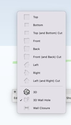
As well as making it easy to choose which one I want to edit, I can immediately see which component I'm currently working on, and which are empty or not. This is so much nicer than all the dialogues that convey information in hard-to-understand grids and tables.
-
3
-
-
Are we talking about the palette that only appears when you are editing a symbol?
-
1
-
-
For example... if for some reason I wanted the exterior detail to do this, it would be tricky, right?
Because the "profile offsets" bit of wall closure controls, it sets portions in or out based on whether they are adjacent to the window frame rather than per wall component.
-
Yes you're right that in the final detail, it might end up that I'd want an additional component anyway. But at this stage it's more proof of concept to understand what I can and can't do with these wall wrappings.
-
I'm now getting pretty close to what I want, using custom windows inserted as symbols into walls, and using the wall closure options.
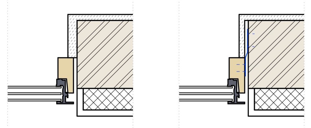
On the left is what I can get in a HSVP without needing to do any fixes in the annotations space. This is already pretty good - I can get the internal and external components to wrap pretty much as I want. The external render (at the bottom of the images) can wrap back to the brickwork, tucking in alongside the window frame leaving a gap of the width that I want. That gap I have made by making the hole cut component of the symbol slightly larger than the size of the windowframe itself (in place of what would be the "shim gap" using a window object).
And the internal plaster finish can wrap round and meet the frame, as determined by the wall closure component of the symbol (I could get it to slightly stand off the frame if I wanted.
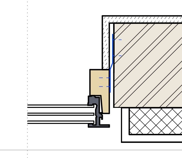
On the right, I've added some stuff in annotations, which I can't seem to do using the wall closure controls. Really I'd like the internal plaster finish to sail slightly beyond the edge of the brickwork opening, leaving a gap behind it where it wraps into the reveal because in reality there will be a metal fixing lug (indicated in blue) in here, which will need a bit of space.
Am I right in thinking I can't do that with the wrapping settings? The closest I can do is what I've shown on the left where I've just increased the thickness of that layer where it wraps into the reveal. I guess I could add another wall component, with zero thickness, in between the plaster finish and the brickwork, which could then wrap and gain a thickness in the reveal to create the void/stand-off but that seems a bit of a clunky workaround.
-
5 minutes ago, Pat Stanford said:
@line-weight I think about is slightly differently. I don't think about "Container Classes" but rather "Container Objects".
I guess what I have is "object classes" and these are intended to control visibility per object type.
In these classes might be a mixture of simple objects and "container objects".
Like so you have to be careful about unintentionally hiding things but if you are deliberate about it, I find it's a very useful way of making visible/invisible things that satisfy two criteria rather than just one. I name my classes such that it's always quite clear whether they are a "material class" or an "object class".
-
3
-
-
16 minutes ago, serge_01 said:
@line-weight interesting! my drawings are all in 2D, so it only draws 2D geometry. Would 3D geometry be faster than 2D, i cant imagine!?
My guess is that 2D ought to be much faster than 3D because it doesn't really have to calculate very much to show it to you.
-
-
@pjs8888 it's worth also understanding about "container" classes - you can have a collection of objects in various different classes, grouped together into a group, and the group can have its own class. A group can just have one object in it if you want.
This means that the objects' classes can control things like texture while the container class can control the visibility of the whole group. Likewise you can put a symbol in a class that's used purely to control its visibility. Doing it this way allows you to have a lot of control over which elements are visible at any one time, without relying on the layer system. I tend to try and keep my number of layers to a minimum but that's somewhat a personal preference/habit.
What all this means is that you can have several overlapping methods of controlling the visibility of any object, something you can't do in an application that just has a simple layers system. For example, I tend to use layers to divide building models into storeys. Then classes define what objects are made of *and* what type of object they are.
So, one object might be on the first floor, made of steel and a structural beam. I can set things up using a combination of classes, layers and container objects so I can choose to show:
- all objects on the first floor
- all objects on the first floor that are made of steel
- all objects on the first floor that are structural objects
- all objects on the first floor that are structural objects made of steel
- all objects on all floors that are made of steel
- all objects on all floors that aren't structural
- all objects on all floors except the first floor that aren't made of steel
....and so on - the list can get quite long.
-
3
-
-
5 hours ago, Hugues said:
@line-weight Yes, data visualization can switch object attributes from hatch to solid and vice versa.
You would need to setup appropriate data visualization criteria depending on where your objects are getting their attributes from.Simple example:
You have objects in Class A, B and C that are using attribute by class and you want to override the Fill using data visualization.
Set the Object Criteria to find objects in class A, B, 😄 Class is A OR Class is B OR Class is C
Set the Display Criteria to Objects using function Class.
You'll see the list of classes. Set the fill for the classes you want to override to whatever color you like.Thanks. Yes, I think I understand this in principle.
I didn't explain myself very clearly in my first post.
I usually have a large list of material classes set up, each with a different fill colour. And then at some point I change them to hatches. But I notice that the class, even after I have given it a hatch, still "remembers" the fill colour:
This gives the impression that the class has both a fill colour and a hatch. And it would be very useful if I could flip between these two states, but have that apply to all of the materials classes in my drawing.
In other words, have data vis find all the material classes, and just make that change in the "style" dropdown from hatch to solid, or vice versa. Because all my classes are already set up with this dual identity. That is, rather than me having to go and choose an override for each class individually. And it would still work on any new classes that I import in from somewhere else.
-
1 hour ago, Matt Panzer said:
Right. The reason for this is because the Door and Window still create some 2D geometry (2D loci and a polygon with no line thickness) and can also display 2D ID Tags. So there's always something in the PIO's 2D component. There are reasons for this 2D geometry so it's not as simple as having the PIO not create it.
Ok I see. This only applies in plan view, I guess? Hence vertical sections behave differently?
-
The fact that there is the option to do it within the window PIO's settings, would surely suggest that it's at least "valid".
-
5 hours ago, Matt Panzer said:
Thanks for taking the time to record this.
Firstly, regarding the wrapping to the insert: the key point seems to be that I have to give it the wall closure component. I'd hoped that might be generated automatically ... like the wall hole component is ... and that this might be an advantage of using a custom symbol inside a window object.
Regarding the stuff you have to do in order to get the sectioned 3d geometry to show up in a "display 2d components" HSVP - I think what you are showing is essentially the same as what I worked out via trial and error.
My question here is, is there a good reason that it's necessary to go through all these extra steps? It seems to me that if the symbol has no 2d component, it would be logical just to section the 3d geometry. That's what seems to happen in "regular" sections.
I've just done some experiments simply placing the symbol into the wall (rather than wrapping it in a Window POI). Compared to using the Window POI method, there's one extra bit of work I need to do, which is to give it a wall hole component. But seeing as I have to give it a wall closure component anyway, this is quite easy to do. The wrapping then works fine.
Additionally, placing the symbol (with no 2d components) directly into the wall means that in the HSVP, it sections as I want it - I don't need to go through all those extra steps, adding a locus to the 2d component and so on.
So for me, it looks like placing the symbol directly into the wall is the least painful method. As far as I can see, the only real disadvantage is that it can't then report as a window object (not something that matters too much for me).
-
1 minute ago, zoomer said:
I do not really understand the reason why you insert your Symbol custom
Windows into the Window PIO Container.
Wouldn't horizontal Section (and probably Wall Closures) work better with
Symbols directly inserted in Walls ?
In this case you don't want 2D appearances replacing the true cut appearance.
I think in a Wall cutting Symbol you could do so if you want.
But I would think this would no more work if such a Symbol is "occluded" for
2D appearances when inside a PIO (?)
Yes, I have been wondering whether I should just insert them directly into walls, and was going to experiment with this.
But I thought the advantage of doing it within the window tool would be that it will automatically make me "wall hole" and "wall closure" components, whereas if I just use a symbol I will have to make these manually.
Also, that it would more easily let me set things like the height of the window in the wall, and let me report it as a window object in schedules etc (although, this is not really so important for me).
-
1
-
-
Another issue - now looking at wall closures:
Is "wrap to insert" supposed to still work if I'm using a custom symbol within the window tool?
If I use these same settings for wall closure applied to a standard window and a custom one:
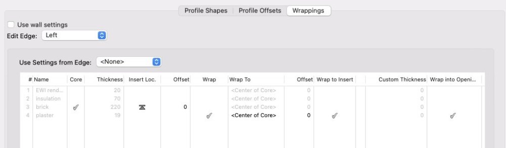
Then the result is this:
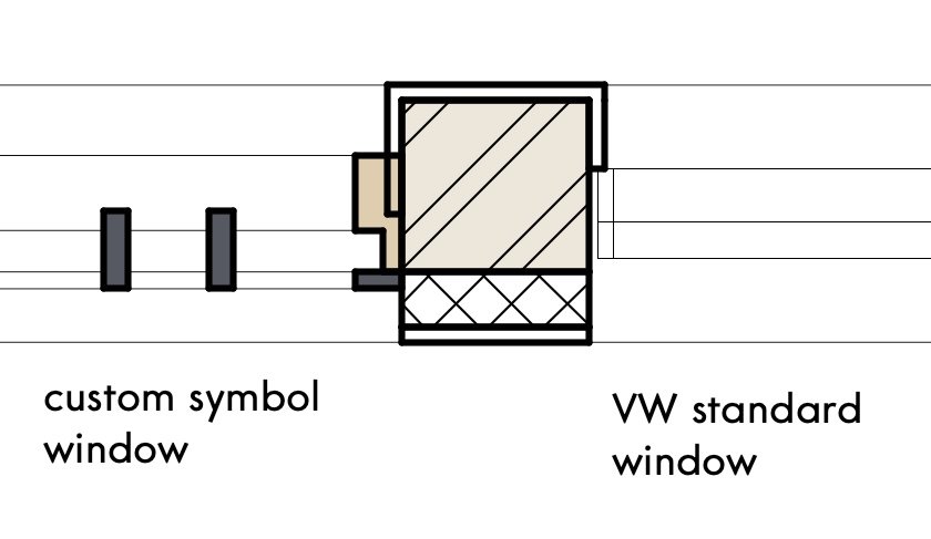
On the right, the "plaster" layer wraps to the face of the window, but on the left it ignores it and carries on the midpoint of the window frame (NB it's not going to "center of core" either).
-
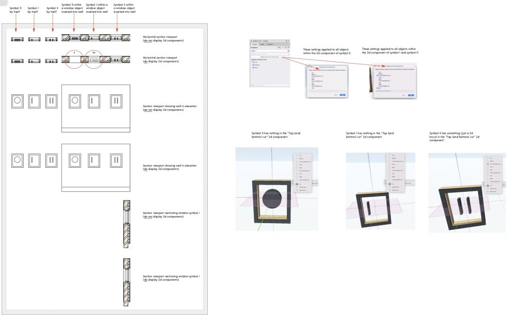
Screenshot of sheet layer in the sample file
-
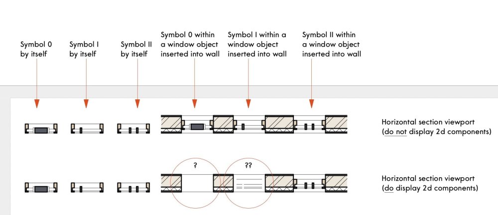
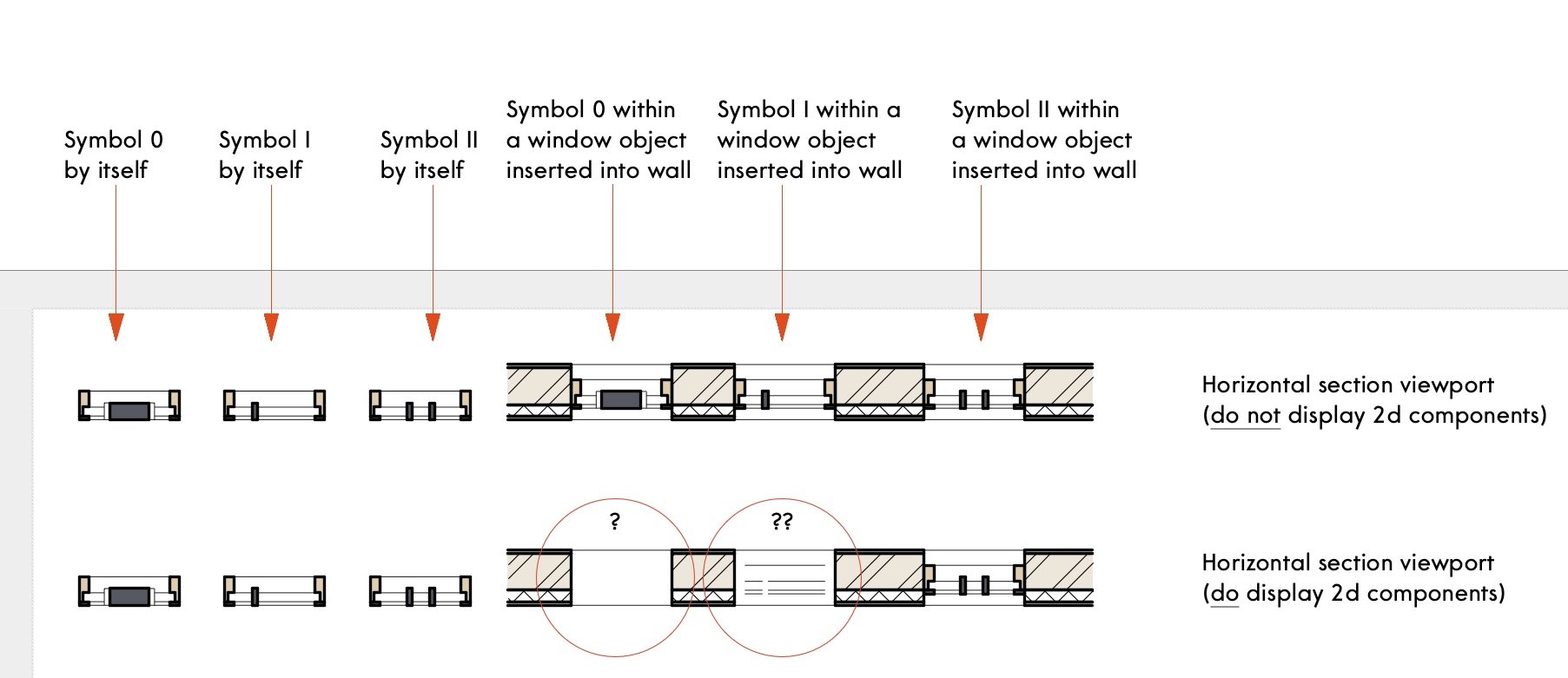
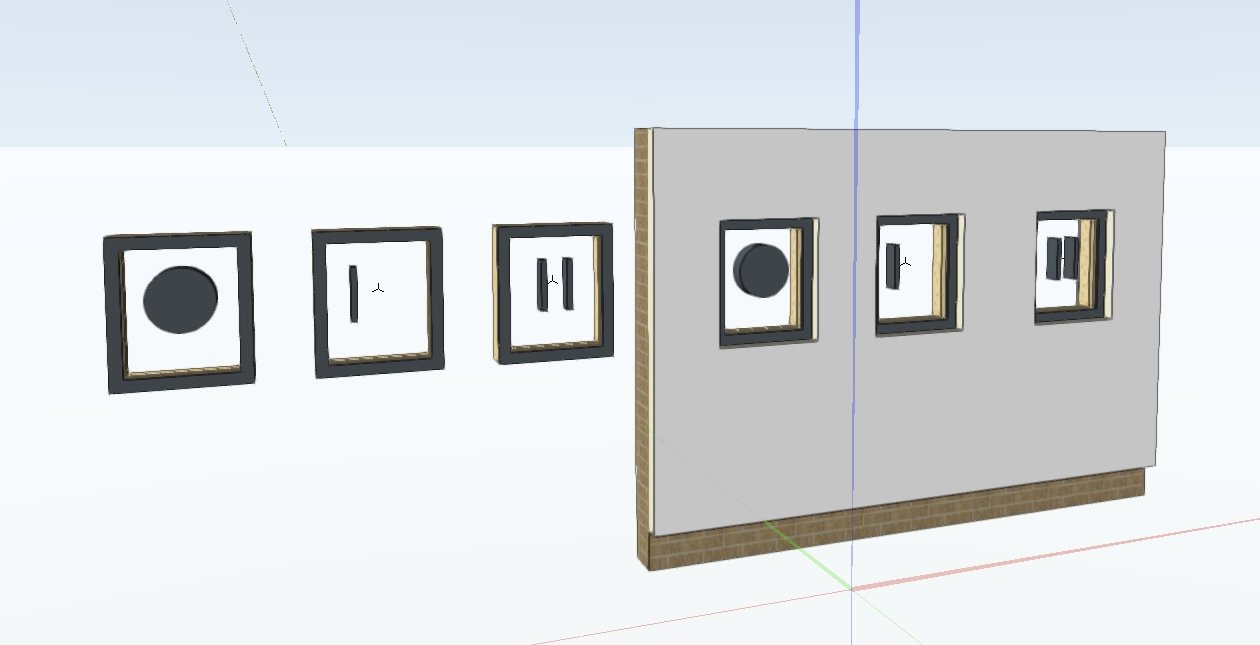
I've been trying to establish a robust way of getting windows that use a custom symbol to display as I want in Horizontal Section Viewports.
Basically I want to have HSVs with "display 2d components" turned on but I want my window objects to be shown in section, as in a real section through the window geometry, not a 2d component representation.
My initial hope was that if the window symbol had no "top or bottom cut" 2D component, VW would simply default to sectioning the symbol 3d geometry. That's what happens if the symbol is just floating on its own - but if it's within a window object, it just shows a blank space.
Then I realised that there are some settings that I can apply to the objects within the 3d component, using the "display with 2D components" button. Doing this makes some elevational lines appear in the window opening but no section cut geometry.
To get it to work fully, it seems that I have to put something in the 2d component (just a single 2D locus seems to do it). Then, the window appears properly.
Is this what's supposed to happen? Or is there something I'm missing? The same problem seems not to exist in "regular" sections.
I've attached a sample file (VW2023 version). There is further explanation in the sheet layer.

-
9 minutes ago, Tom W. said:
Well I think earlier on you were suggesting something different. I'm talking about having objects in the drawing with data attached to them in the form of Record Formats. A worksheet will look for these objects + return the record data. You can edit that data in the worksheet + it will feed through to the record format fields for the objects. It is two way. If you then have Data Tags associated with those objects also returning that data, when you edit the data in the worksheet it will therefore be edited in the tags as well. You can also set up the tags so that they feed data in the other direction to the worksheet. My point earlier was that you need objects in the equation somewhere, you can't just have tags + a worksheet, although Pat proved me wrong on that when it came to tags + records so don't quote me on it!
When you talked about a data tag that lists what plants are planted in that pot I assumed you meant that data was attached to the flower pot object in the form of a Record.
I was imagining that the planting data would be in a record attached to each pot yes ... but that a data tag associated with a pot would show this info plus info pulled from elsewhere.
What I am asking/suggesting in this thread is probably a bit confused, because I haven't fully got my head around how all this works. In particular I don't use worksheets a lot.
I should probably come back to this when I have a bit more time to think this through more thoroughly... rather than asking further ill-defined questions just now.
-
44 minutes ago, Tom W. said:
In a worksheet no?
Pulling from a worksheet is one of the things I mentioned in my first post, yes, but as far as I understand this isn't actually possible.
-
14 minutes ago, Tom W. said:
This is how Data Tags work as standard. Just set the Record Format as the Data Source.
I guess I mean a scenario where the data tag is associated with an object but I want to pull data from some other object in the drawing.
For example I have 10 flowerpots each with different flowers in, and each has a data tag that lists what plants are planted in that pot. But the flowerpots are the same and I have a flowerpot specification. I'd like to show that in each flowerpot's data tag but I'd also like to be able to change that specification at a central location, which could be an unattached record format using its default values, like in @Pat Stanford's example. But could it also be in the form of a record attached to an object in the drawing.
-
Thanks for this. It will certainly be useful to have this to take a close look at if trying to set up something similar.
If I understand right, the data this is pulling is the "default" values for each field in the record format. And that record format just exists in the resource browser, it's not attached to any object in the drawing.
Would it also be possible to have it set up so that it pulls the values from an object in the drawing, which uses that record format? So it would be pulling the values contained in the fields associated with that object rather than the record format's default values.
Obviously in this case the formulas would have to specify exactly which object that was.
In the expressions you have used, does the term 'Universal' basically tell it to use the default values?
-
There's a column in the table that I made as part of this exercise that's about whether the class can be set...
-
2
-


Window with symbol: inconsistent behaviour in Horizontal Section Viewport
in Troubleshooting
Posted · Edited by line-weight
Ah yes - I see.
I can get my version to do the same:
Giving a -100mm offset in the "profile offsets" tab for "exterior":
And it makes that offset happen along the boundary between the wall components.
But if I put a -100 offset in the "interior" part something different happens, it applies the offset in line with the inside of the window insert:
Which is why I think I'd decided this couldn't help me.
I'm not clear how it decides where the offset step-back is giong to happen... do different rules apply depending whether it's inside or outside of the wall core?