


axhake
-
Posts
92 -
Joined
-
Last visited
Content Type
Profiles
Forums
Events
Articles
Marionette
Store
Posts posted by axhake
-
-
-
It would be really useful (and consistent) to have a search / filter within the create “New Class” window when selecting “Import Classes”.
If we have a long list of classes within a file to chose from it can be time consuming to have to keep scrolling through long lists of classes.We have the search / filter in the other class / layer panels so why not here?
-
I've added an update to another post that is relevant to this one
-
- Popular Post
- Popular Post
Sorry for the delay in posting but few things came up.
After chatting with @line-weight I promised a workflow to try out.
I have also created a few Marionette network to make things a bit quicker.
Main NURBS problems:
Accuracy - Fail to pass through Control Points
Large curves display heavily facetted (segmented)
Often when used to creates solids they leak due to misalignment of surface edges.
Vectorworks segments (facettes) the curve into equal lengths throughout the whole curve when displayed, that’s why the NURBS curve appears not to pass through some of the control points.

We also know that if we try and snap to a NURBS it doesn’t snap to the facetted line work but to the geometry of the NURBS curve; from this we know that what we are seeing is a limitation of how Vectorworks is displaying the curve.
At the moment there is no workaround that will prevent this from happening until Vectorworks addresses the issues with curved geometry (NURBS and arcs) and gives them some long over due updates… I would vote that one up any day.
However there is a “workaround” that will allow us to create NURBS that display smoother.
One of the problems is how NURBS are created and how we use them to generate our geometry.
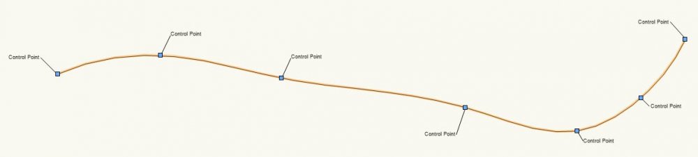
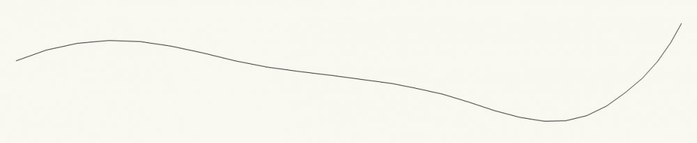
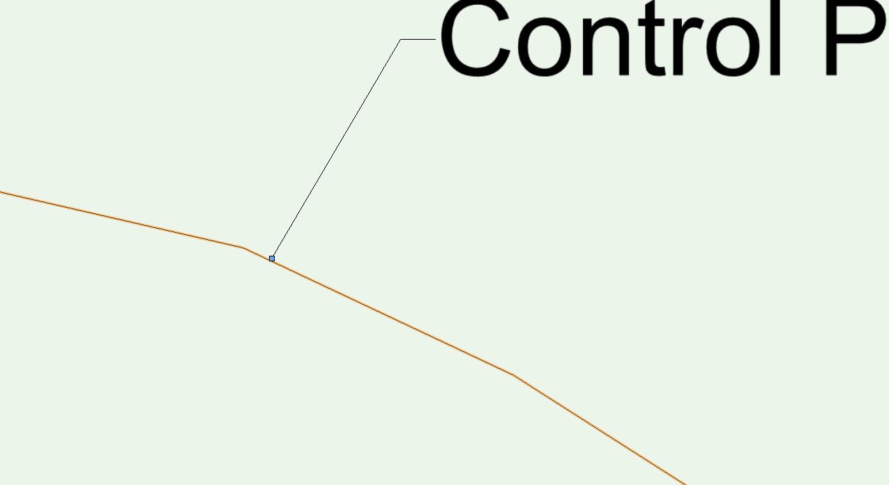
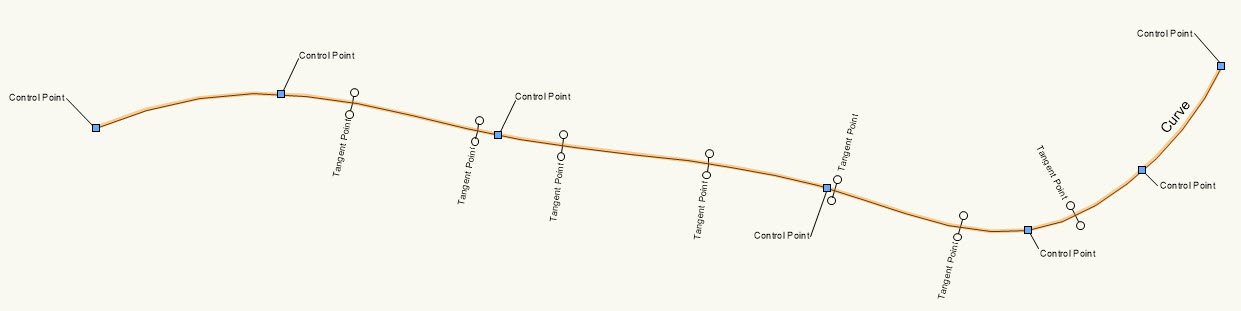
If we look at the example below, the NURBS curve has been placed using Interpolation mode. The NURBS curve passes through a number of control points placed to define the curve which in this example is about 90m long.
Now think of how we would create the same curve using “arcs” and “lines” to approximate the NURBS curve – See image below:
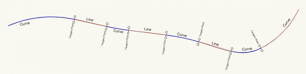
Each arc/line (shown in RED and Blue) is tangential to the next at the points indicated by the “Tangent Points”.
This is how road and rail alignment is constructed using (Curves, Straights and Transitions) to generate a smooth alignment.
NOTE:
We can use the “Analysis Tool” found in the “3D modelling” Tool set to find the properties of a NURBS curve more accurately using the second option “Interrogation Mode.
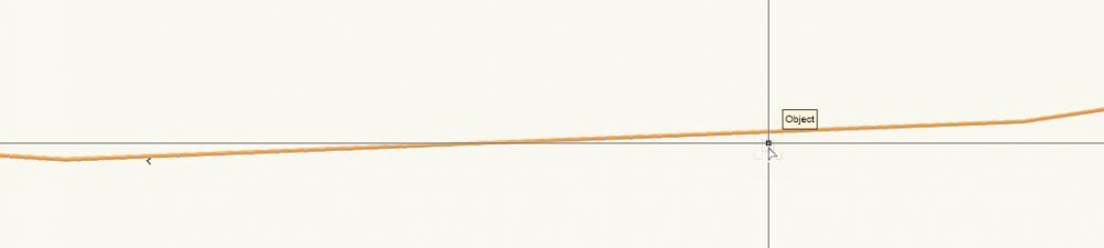
If we now take the “Tangent Points” and overlay these onto our NURBS curve; notice the location of the “Control Points” in relation to the “Tangent Points”… they don’t align.
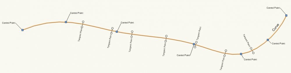
So to be able to create a smoother NURBS curves we need to create our curve taking in to account how we would have create the curve with arcs and lines, placing control points nearer to where a “Tangent Point” would be located and adding more control points to pull the curve to the desired position.
EXAMPLE: (NURBS - Example 1.vwx)
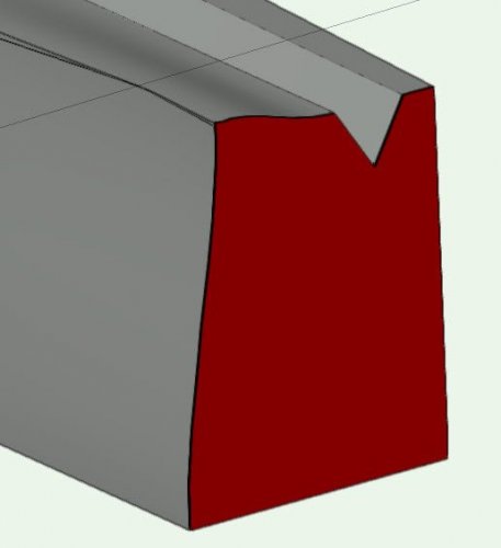
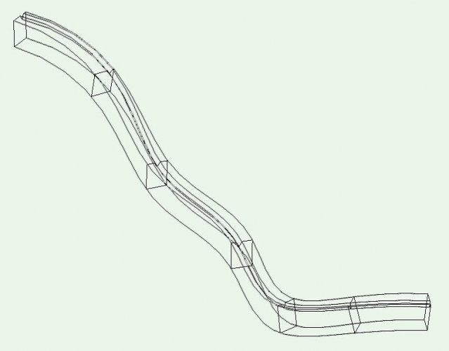
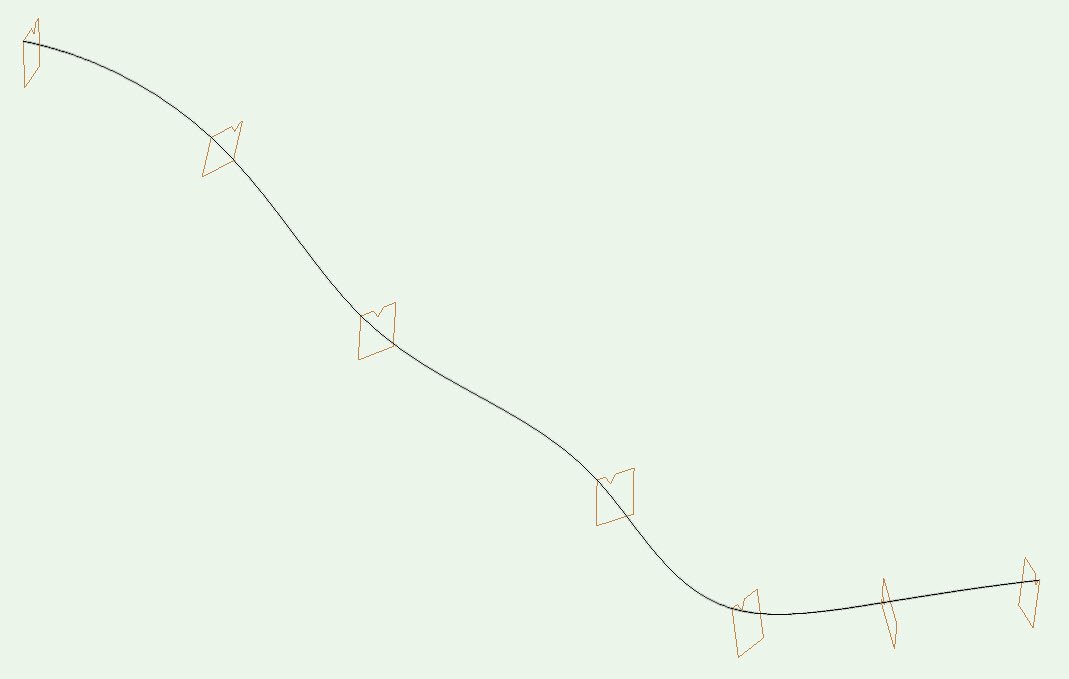
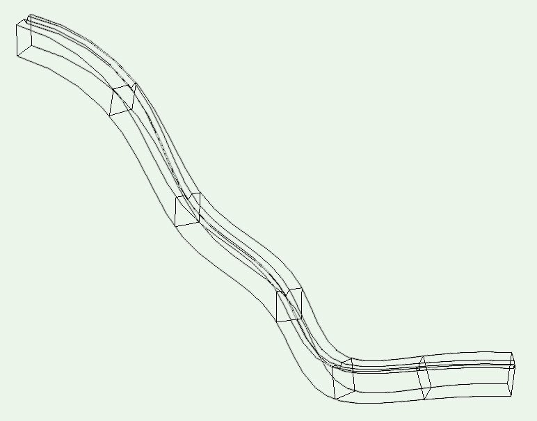
Consider how we would create a solid wall using these seven profiles (one to be placed at each control point – vertical and square to the control point/curve):
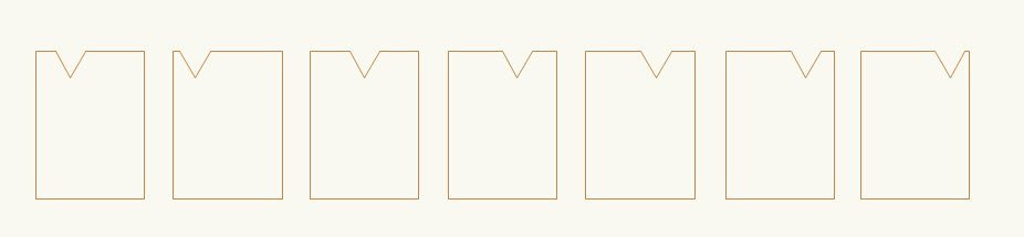
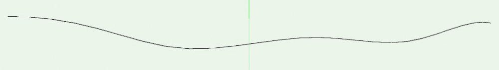
The control path is a NURBS curve (shown in plan)
and in front view:
and in 3D
(NOTE: I have placed a copy of the profile at all the control point locations, vertical and square to each of the control point).
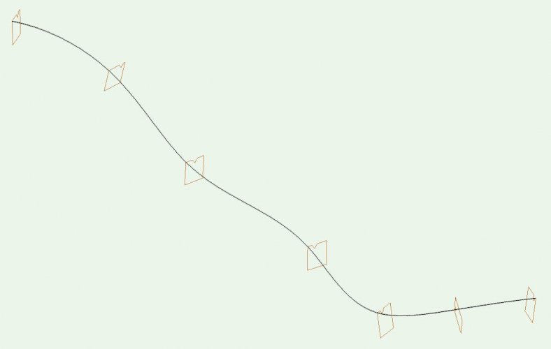
Try and create a solid object that once created aligns with each of the profiles.
As the “V” in the top moves from left to right we cant use the “extrude along a path” tool.
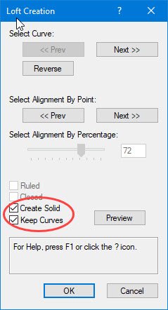
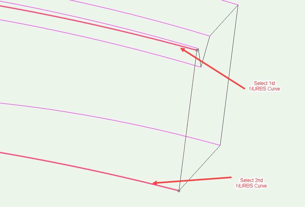
If we try “Loft" – "One rail mode”
Change the profiles to NURBS curves (select all the profiles then go to: Modify>Convert>Convert to NURBS) once done ungroup.
Select the rail (path) then each of the profiles (hold down “Shift key” to select multiple profiles) – Tip: select the same point on each profile to ensure no twisting.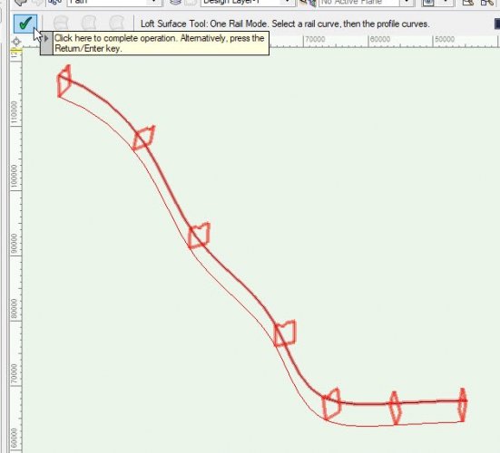
Once done select the green tick to complete the operation.
From the pop up, select “Create Solid” and “Keep Curve”, select OK to finish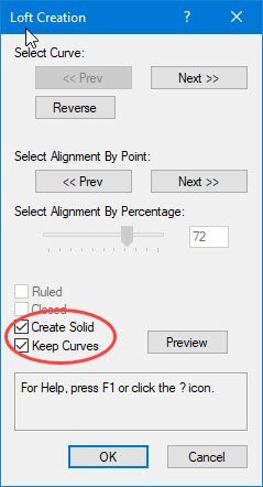
Move the created solid to the “Wall” Class
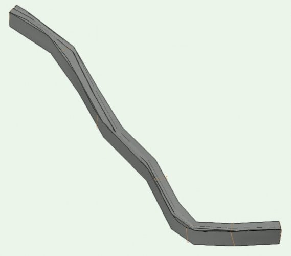
Not very smooth.
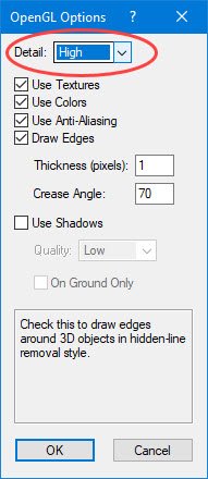
Try changing the “OpenGL Options” to improve curve display.
View > Rendering > OpenGL Options
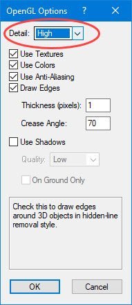
Change “Detail” to High or Very High, then select OK.
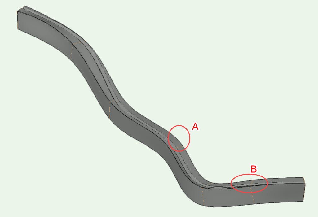
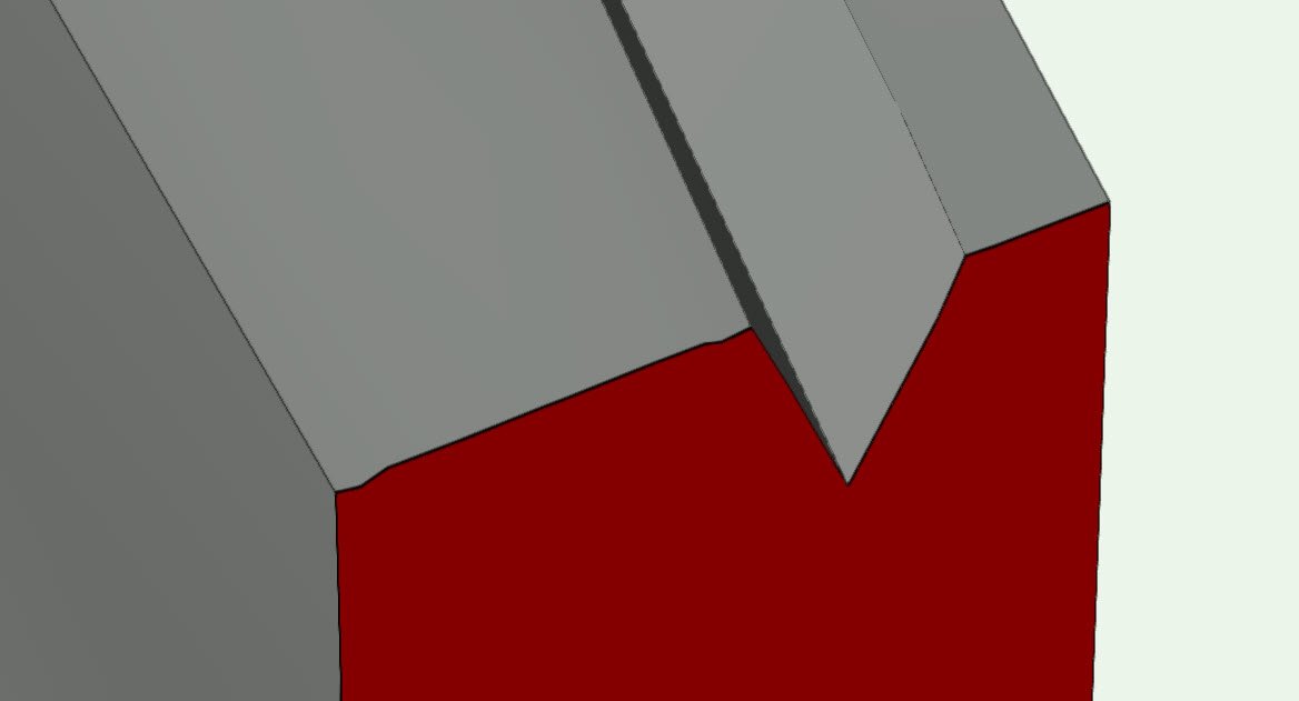
Appearance looks smoother…but!
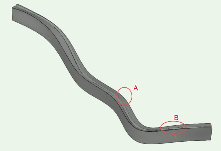
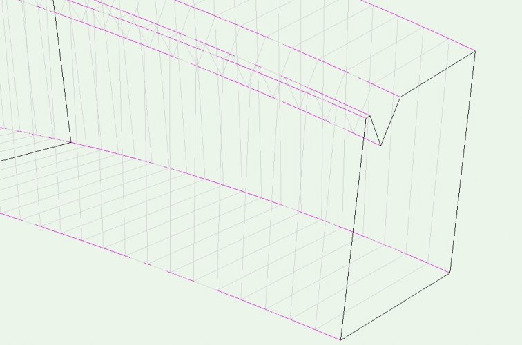
A - The solid created does not pass through the corners of the profile
B – Surfaces don’t appear to be coincident (there are gaps as facetted edges don’t align)
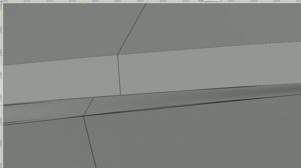
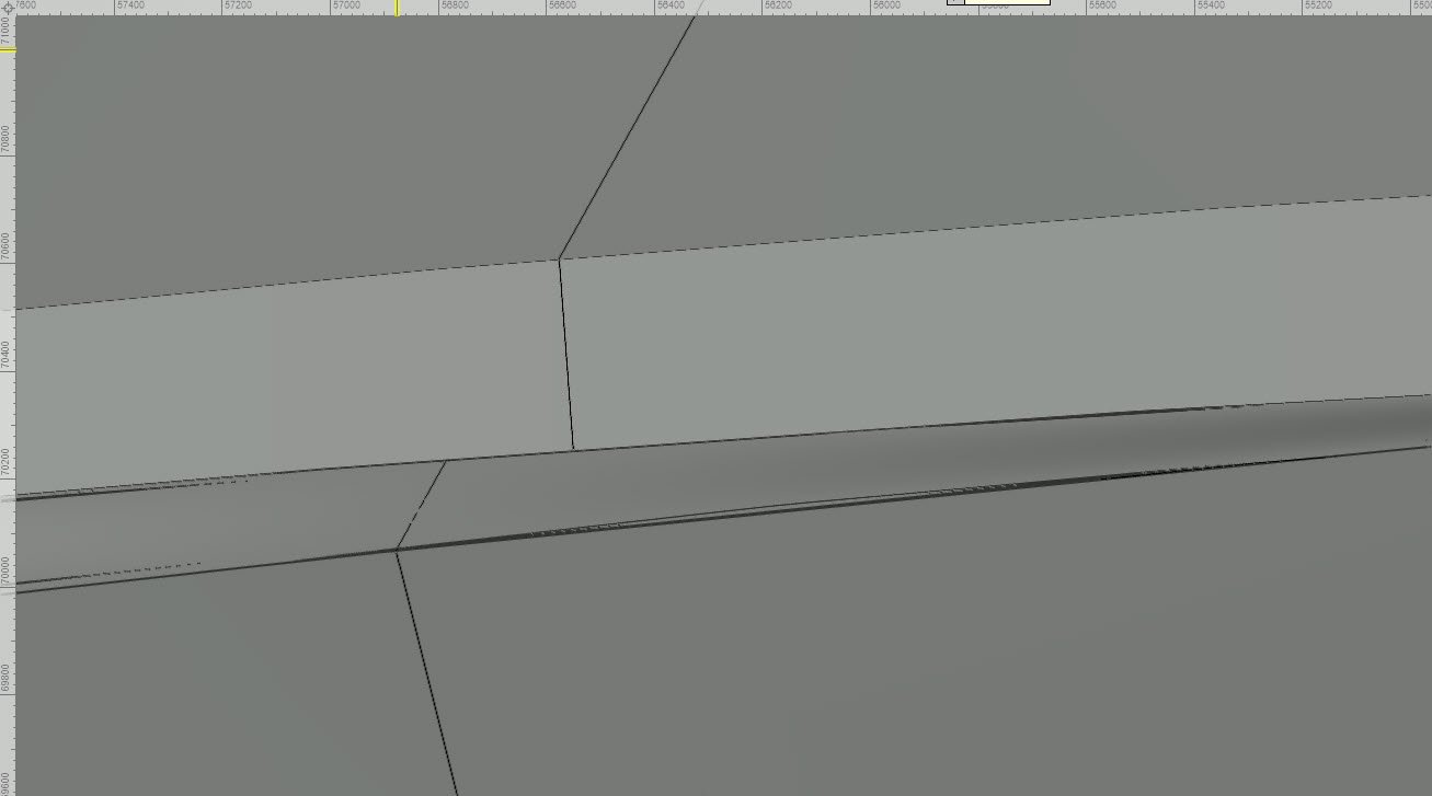
If we use the “Clip Cube” to have a look along the object created we notice some of the surface buckle and twist.

So how can we improve on this?
1.
Copy the path NURBS Curve and the profiles,
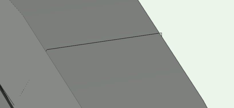
Then place additional NURBS curve through each vertex of the profile (selecting the same vertex in the other profiles as shown below)
You should have 7 NURBS curves in total.
You will notice that the NURBS facetted curve displayed doesn’t pass through the points on the profiles (however the underlying geometry does)
So to fix this we need to split the NURBS curves at each of the control points (where the profiles have been placed).
2.
At each profile (not start or end profiles) “Set a working plane”, use “Three point mode”
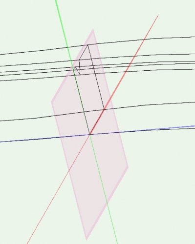
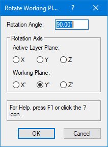
The from the mouse menu (right click) and select: Working Plane > Rotate Working Plane

Set “Rotation Angle” to 90
Set “Working Plane” to Y
Now from the mouse menu (right click) and select: Working Plane > Look at Working Plane
3.
Using the “Split Tool” second mode “Line Split Mode” split the NURBS curves at the profile location
Repeat same process at the other profile locations.
You should be left with 42 NURBS curves, each will now start and end between profile vertexes.
Place these on class “AA_CurveToSmooth” or any other class to isolate them.
4. *******************************************************************************
IMPORTANT: strange things can happen with NURBS that have been modified.
Select all 42 NURBS curves and rebuild them:
Model > 3D power Pack > Rebuild NURBS
Number of points should be set to 4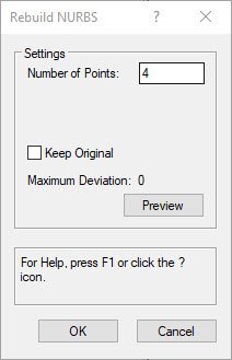
Ungroup when complete.
**********************************************************************************
5.
I have created a Marionette network to do the next bit;
Smooth NURBS _ Keep as Individual Curve(s) _ v3
Place this network in your file and select it, or I have created a network wrapper that can be used to create a menu command,
In the OIP there are some options.
a) Select the curve by criteria:
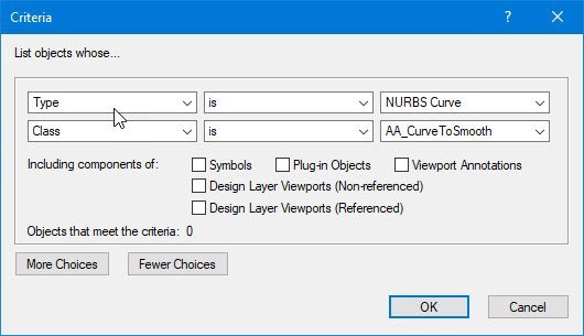
Select:Type – is – NURBS Curve
Class – is – <the class you have placed the NURBS curves on to isolate them>
b) NURBS curve degree: Keep this as 1
c) Number of points to divide curve: Try something like 20 to start with
d) Set colour PINK: Tick this (easier to see how the curve is smoothed in relation to original curve)
e) Delete Original Curve: Leave this UN-TICKED for now.
f) Join to form one curve: Tick this (all adjoining short length will be joined to recreate the 7 NURBS curves.
Select RUN
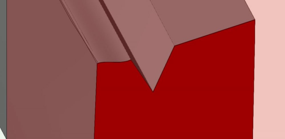
- Each curve (between profiles) has now been recreated using the underlying geometry to define where each of the new 21 control points is placed (creating 20 facets) per curve
- Each curve between profiles has then been joined to form one NURBS curve (back to 7 NURBS curves)… now each of the curves has a control points display correctly passing through the vertex of each of the profiles.
If you are happy and the geometry looks smoother enough for your needs run the script again and tick “Delete Original Curve”
If not run the network again and change the number of point:
- Smaller number less smoother (less vertices)
- Larger number smoother curve (more vertices)
g) You need to Ungroup the graphics after to break them from the script..
6.
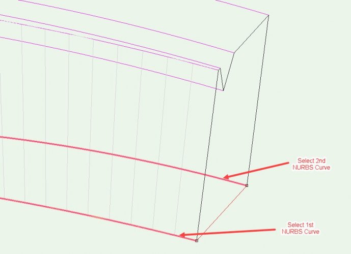
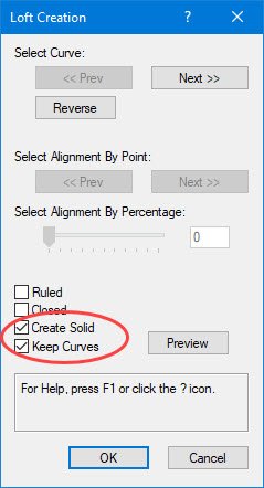
Now using the “Loft Surface Tool”, first mode “No Rails Mode”
Zoom to one end of the wall and select two adjacent NURBS curves
Select the Green Tick to complete
From the options box that is displayed select both “Create Solid” and “Keep Curve”
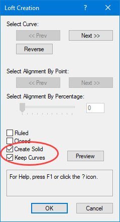
Select OK to finish.
With the solid still selected change the class to: AA_Surface Temp
Tip:
To make things easier set: class visibility of: “AA_Surface Temp” to Gray
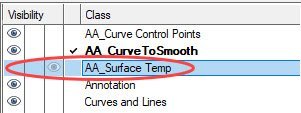
Set Render Mode to: Wireframe
This makes it easier to see which NURBS curves have been Lofted and to be able to select the next set.
Repeat the same process with the last NURBS curve selected and the next adjacent curve.
Repeat this process until all sides have been created.
Set: AA_Surface Temp as the active class
As the end profiles are a simple shape Delete them and recreate them using the 3D Polygon Tool.
Repeat for the other end profile
Set “Render Mode” back to to: openGL
Set “class”: AA_Surface Temp as Active Only (don’t want to see anything else)
Select all solid surfaces and the two ends.
Right mouse button, and select “Add Solids”
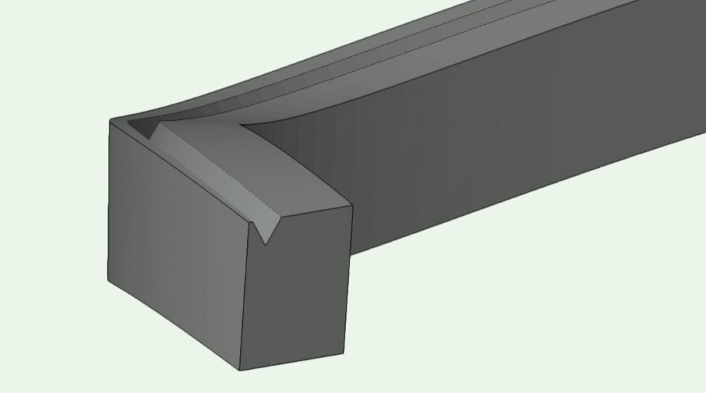
You should now be left with one nice smooth object created using NURBS with no buckling or twisting of surfaces and the solid generated passes through each of the control points/profiles.
Note:
If having set “Detail level” to High or Very High in OpenGL Options is slowing things down set it back to low and see how it looks.
You can use this process to create some very clean and smooth geometry or anywhere you need to display smoother curves.
Many thanks to @sbarrett for help with the network to find the control points.
I'm still trying to find a way to automate the splitting of NURB curves at the control points so will update if this can be done.
NURBS - Smooth - Marionette - v2021.vwx NURBS - Smoothe Test - v2020.vwx NURBS - Smoothe Test - v2021.vwx NURBS - Smooth - Marionette - v2020.vwx
NURBS - Smoothe Test - v2018.vwx NURBS - Smooth - Marionette - v2018.vwx
-
 4
4
-
 1
1
-
I like that, works nicely.
Many thanks to you all for all you help with finding a solution to this.
Hope you and your families all have a great Christmas and lets hope that next year is good for us all.
Alan
-
It's sound so easy but have been trying for some time to do this.
Just about to have dinner so will have a look at this way of doing it later and let you know how I get on.
Just on an off chance anyone have any suggestions on how to split a NURBS curve at it's control points using Marionette, been trying to find a way of doing this for some time as well, another one I thought would be so easy...alas NOT 🙁
-
😀 That worked providing I add an output node to my wrapper, but unfortunately it doesn't if it's included inside the wrapper so unable to create a menu command.
I'e., if you were to select your three nodes and then wrap them it still creates a group when finished which is the problem I have as you are unable to create a menu item unless everything is inside the wrapper.
-
Hi Gregi,
Many thanks, will give this a try shortly and let you know how I get on.
-
Have a look at this, I created in V21 and exported to 2018 so you should be able to open OK
See if you can trim the parapet back a bit by following what I did.
Alan
-
Hi Sara, Thanks for the reply.
I am aware of the reasoning behind the grouping being tied to the script it’s just when you have turned you script into a menu tool and are trying to use it to manipulate existing geometry I find some times that I am having to do a whole bunch of extra ungrouping, if there was a way to have the script not create a group after it is run that would be useful.
The only way I can think of doing this would be to encapsulate the Marionette script in a Vectorscript and have that ungroup that way, if that is possible?
Alan
-
As you have the solid you require you could simply
1. Switch to top or top/plan view
2. Place a line perpendicular to the curve at the point you want to trim the parapet back to
3. Using the Split Tool (second mode “Line Split mode”) cut your solid using the line in (2) as a guide.
4. Using the “Extract Tool” (Preferences – Tick Create Planar Object”), select the top faces of the wall (use Shift to select multiple)
5. Ungroup and extrude above the top of parapet, then extrude the back face beyond the outside faces of the parapet
6. Use the “Taper Face Tool” to close any gaps in the extrusions)
7. Select the extruded blocks and “Add Solid”
8. Select the block with the parapet and the new block created in (7) and then “Subtract Solid”… no parapet 🙂
9. Select the two and "Add Solid" to get back to one object
-
Doe's anyone know if there is a way within Marionette to get the finished script to ungroup it's self when it finishes?
I.e., I have a script to create a 3d line from points.
When Marionette finishes the 3d line is in a group requiring a manual ungroup to be able to join it to the next line, this can be time consuming when you run the script multiple times.
-
Hi @jblock
Have downloaded SP2 earlier today and this seems to be resolved this problem, coordinates are reading correctly now.
many thanks
-
2
-
-
VW 2021 - sp1
I have just finished drawing up some 2D details and re-visited a project I was working on some months ago which highlighted the problem.
When I create a template using real world coordinates and set the user origin to align with the internal origin; I always create a layer and class named: z_Shared Origin
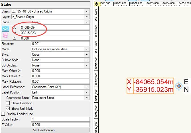
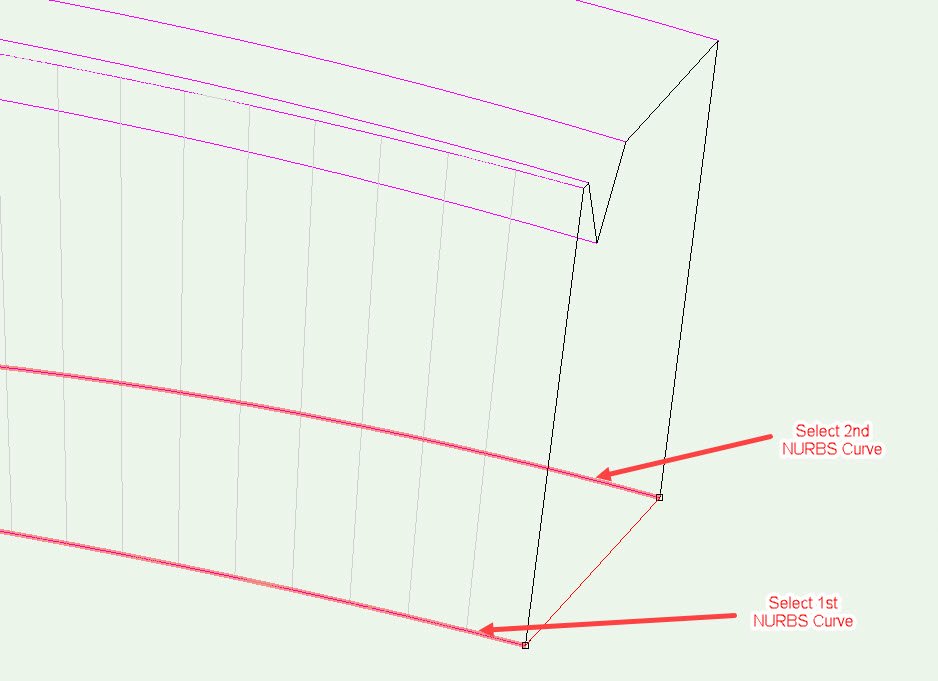
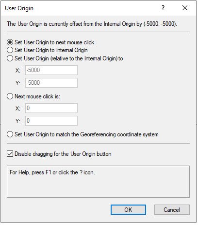
On this layer/class I place a Stake Object at the internal origin to show the coordinates, I then open the user origin window and take a screen shot and past this onto the same layer/class, move it close to the internal origin (re-size as needed), then LOCK the pasted image in place.
Once done I then turn the layer off so it is not in the way. - see example below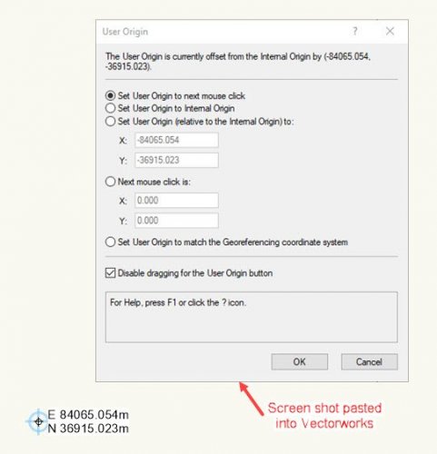
At any point I can turn the layer z_Shared Origin on and check that the coordinates of the stake object align with the details of the screen captured image pasted in
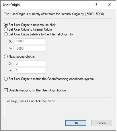
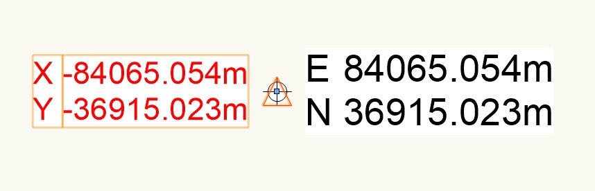
In the above example the user origin has been moved -84065.0543m to the left and -36915.0233m down to align with the internal origin, thus the coordinates of the now relocated user origin display correctly.
Over the last few years this has proven invaluable when opening a file and finding the user origin has moved, I know what is should be reset to, also when sharing with others is is a way they can check it is located correctly.
In the last few releases the problem of user origin moving all by its self seemed to have disappeared from what I have found.However I have just opened a project I was working on some time ago and wanted to continue modelling the as-built information.
I updated the file to VW 2021 and turned on the layer z_Shared Origin and checked (see image above) and all seemed to aligned OK.I then started to place some as-built setting out points provided and was surprised to see they were showing as negative values.
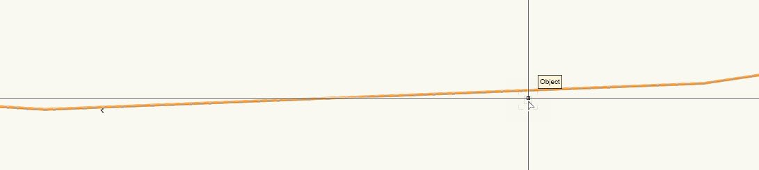
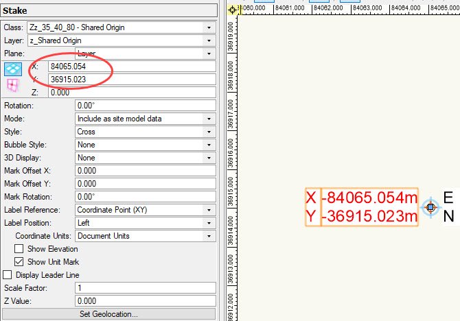
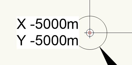
I placed a new Stake Object at the project origin (internal origin) - see new stake object (shown in RED), the coordanates are a negative value!

I checked the User Origin settings and also the display on the rulers also the coordinate read out (bottom right) all displayed the correct (positive values).
Note: The original stake object has not updated?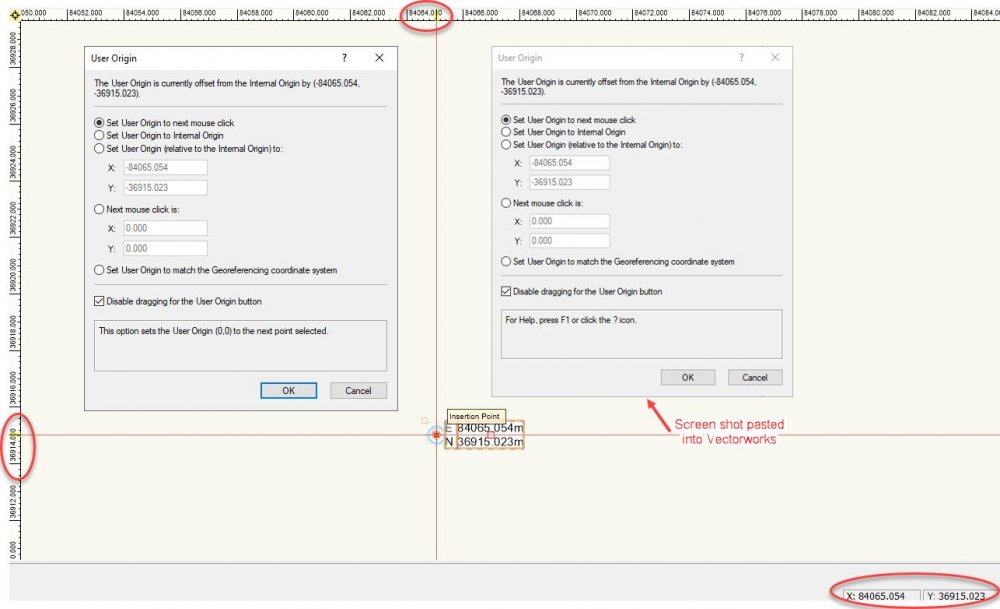
Selecting the new Stake Object (or the original Stake object) and checking the OIP both displays positive values.
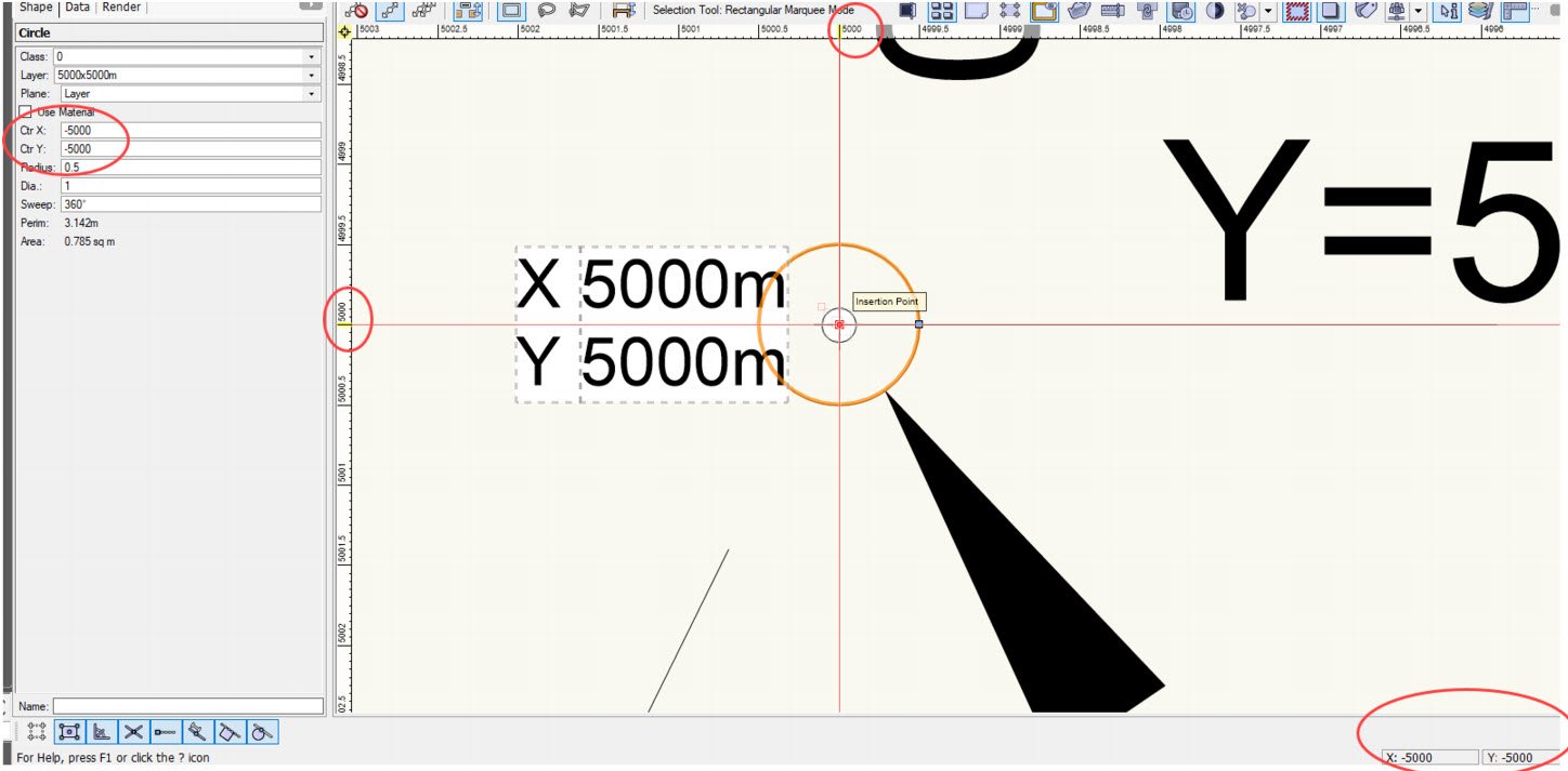
I tested this with some new files as shown below.
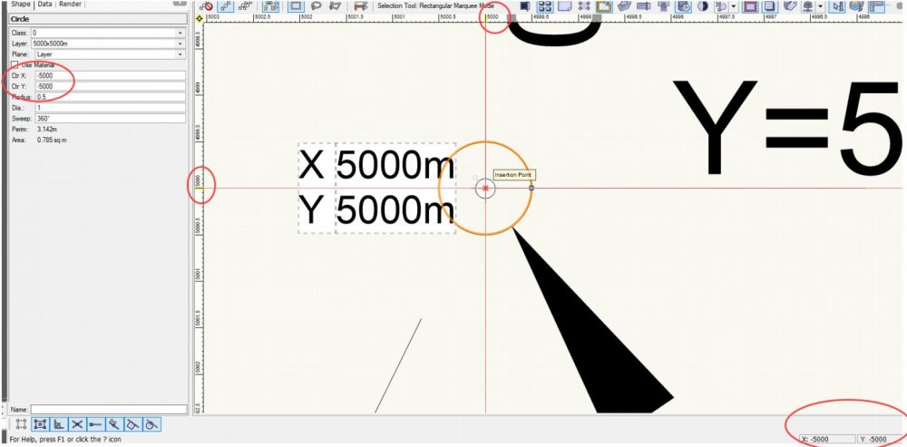
Test 1:
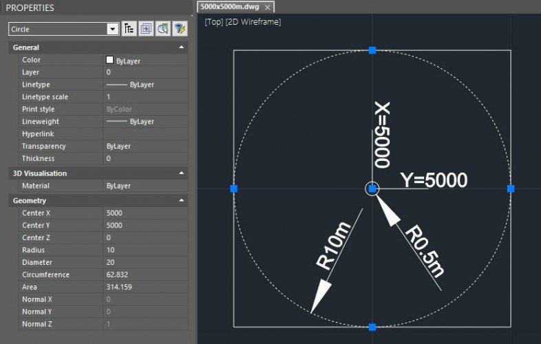
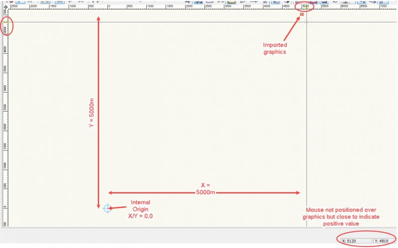
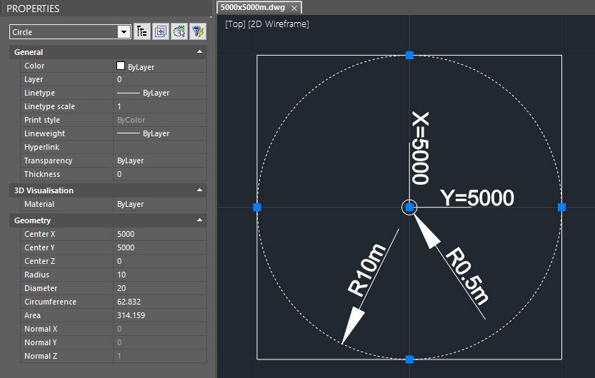
I created a simple AutoCAD file ( 5000x5000m.dwg ) with a circle and square placed at:
X = 5000.000m
Y = 5000.000mas shown below.
1. Created a new blank Vectorworks file and set all layer sacle set to 1:50.
- (VW 2021 - Dont forget to set a test size for the class until they fix the default fornt size or no test will display when you place a stake object)
2. Imported the DWG file ( 5000x5000m.dwg )
- Tick change current VW units to match DWG filer units
- Under Advance set Location to: Centre first import
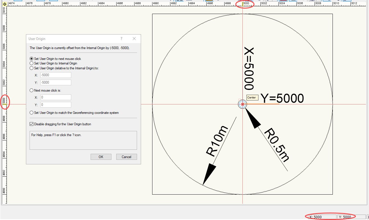
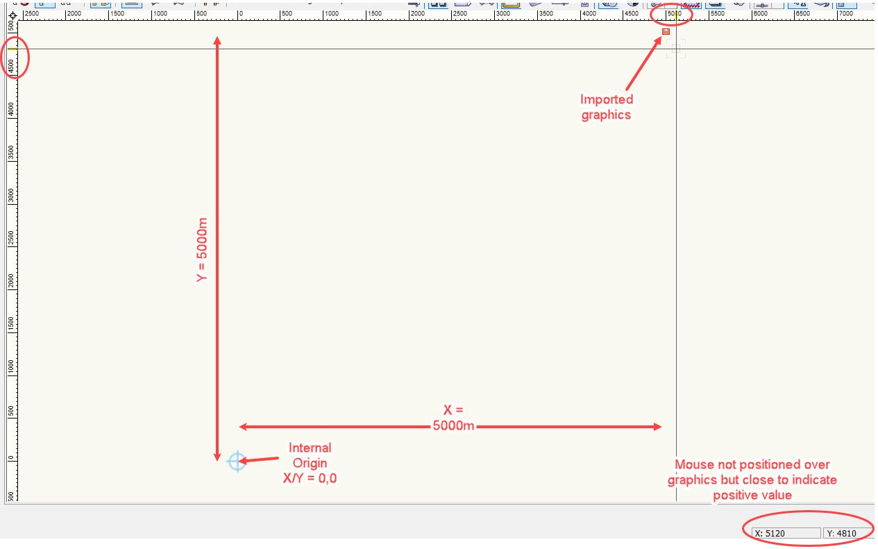
3. Once imported switch to Top/plan view and placed the cursor over the centre of the circle, coordinates on the ruler and coordinates bottom right displayed correctly
X/Y =5000m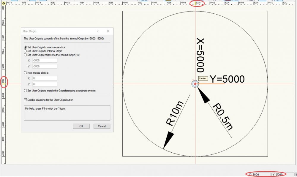
4. Checked internal origin and all looked OK, X/Y = -5000
(Centre of the circle being centre of all graphics / user origin has been moved (offset by) -5000 in both the X/Y to align over the internal origin)5. Placed a Stake Object onto the internal origin/centre of the circle to check, however this now displayed as negative values?
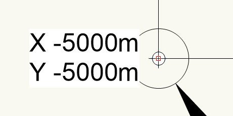
User origin, rules and bottom right coordinate display are correct but stake object display negative values of X/Y - 5000
Test 2:
1. Created a new blank Vectorworks file and set all layer sacle set to 1:50.- (VW 2021 - Dont forget to set a test size for the class until ther fix the default fornt size or no test will display for the stake object)
2. Imported the DWG file ( 5000x5000m.dwg )
- Tick change current VW units to match DWG filer units
- Under Advance set Location to: Align with Internal Origin
- You will be presented with an option saying that you are about to import objects far from the internal origin - Select ( NO ) to continue (as this test we want the objects imported to be place at X/Y = 5000 and NOT centered about the internal origin.)
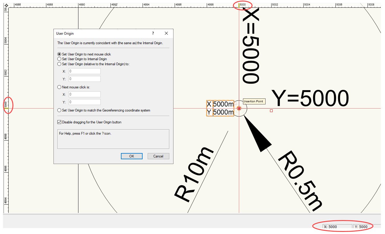
The graphics were imported correctly, 5000m away from the internal origin.
2. Placing a Stake Object at the circle center displayed correctly, X/Y = 5000
- The rules and coordinate display bottom right display correct, all saying X/Y = 5000.
- Check the Internal Origin which was correct being 5000m away from the graphics at X/Y 0,0.

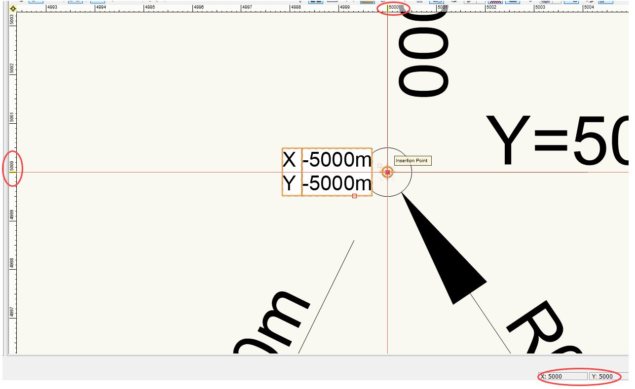
3. Selected: Tools > Origin > Centre Drawing on Internal Origin (to align/offset everything relative to the internal origin)
4. Checking the rulers and coordinate display bottom right both displayed correctly X/Y = 5000
but the stake object now displayed as X/Y as a negative value of X/Y = -5000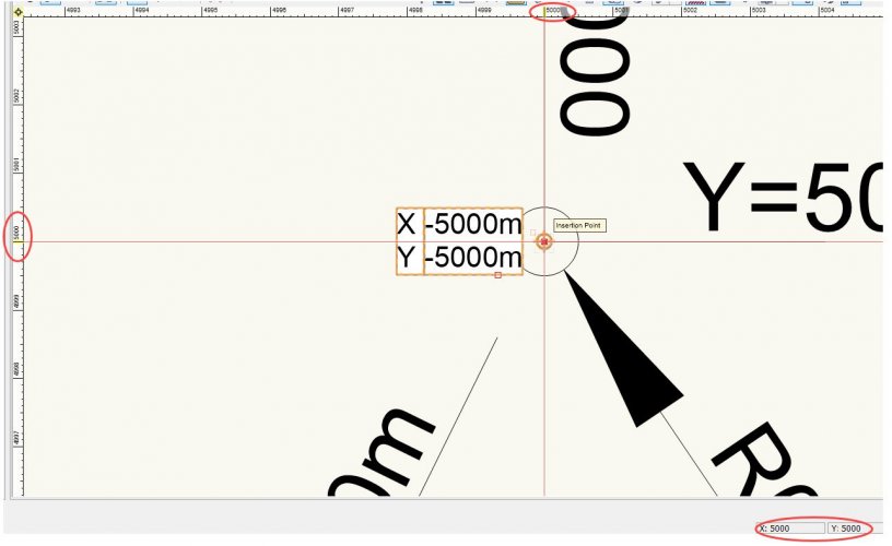
5. Checking the internal origin this showed X/Y as -5000 which would be correct as it had to relocate everything -5000 in the X and Y axis.
6. The only way to get the Stake Object coordinates to display correctly is to change the internal origin to positive numbers, i.e., X/Y = 5000
- The stake object now will displays correct X/Y = 5000
- The rules display correctly X/Y = 5000
- However the coordinate display bottom right is incorrect displaying as a negative value, as X/Y = -5000
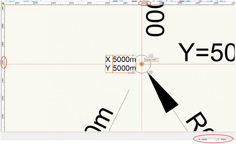
7. Whats intresting is if we check the centre of the circle in the OIP this shows X/Y as -5000 (should be 5000)
There is something terribly wrong with all of this
Test files attached for reference.
-
1
-
If you have the leg path why can't you just create the side profile that you are trying to achieve and just extrude it?
-
Looks like the same problem with the "Stake Tool", if not text style has been defined in the document then no text displays, setting a text size then using the stake tool and text is displayed.
-
it's annoying isn't it, especially when you are trying to work quickly.
Not sure if you had submitted this as a bug but I just did so as to remind them this is still a problem to be fixed.
-
1
-
-
Is there a reason why mesh objects are selected when partially within a marquee area, all other object types obey the section mode – see video below.
-
Hi Matt,
One of the first things I checked.
Have just created a video to demonstrate.
Alan
-
1
-
-
Sorry forgot to attach the file, I have just created a new file and added grid lined.
Similar pattern, tested and same thing as above
-
Just trying out the new Grid tool in VW 2021 and it is a vast improvement to what we had, thank you.
I have just recreated a grid from a previous project and noticed a small problem.
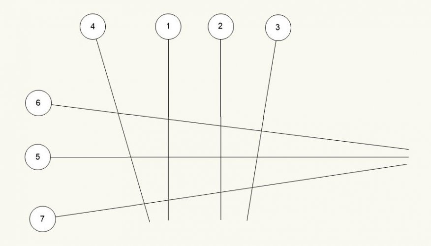
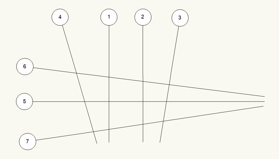
To demonstrate I have created a small grid as shown below.
Grids 1,2 are both vertical
Grid 5 is horizontal
Grids 3, 4, 6, 7 as can be seen are not vertical/horizontal.
The example image below is viewed in a Top/Plan view.
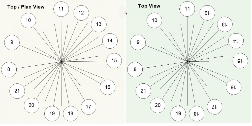
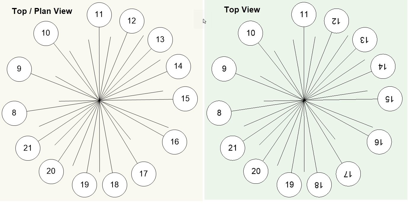
However if I then switch to a Top view, look at grid ( 3 ) the text is rotated.

In Top view grids text between 12 and 6 o-clock get rotated 180 deg... why?
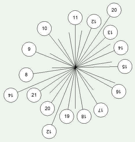
And if you add bubbles both ends
-
Is it possible to share the file or part of the file so we can have a look?
-
I cant’s disagree with you regarding Parasolid's, we are being limited by the tools and features Vectorworks has implemented and at a disadvantage with no workarounds when it comes to display and presentation of curved/NURBS geometry in the way it converts it to facets.
I have had several projects which I have started in Vectorworks and spent many days working on only to have then rejected by the client due to the poor display and accuracy of the large curved elements when collaborating with others using alternative packages who require accurate geometry to work to. Tried every workaround I could think of after looking on the forum and talking to others finally having to abandon and re-create them in Rhino and then borrowing a license from a company I help out at and finish the projects off in either Revit or ArchiCAD depending on what licenses they have free at the time. Not ideal but was they only was I could deliver.
If you look through the forum you will see that the issues with Parasolid's/NURBS have been around for some time now with no fixes being made. Will be interesting to see if VW2021 has fixed these problems as they say in the “3D Modelling Enhancements”...
“Eleven different tools, and popular objects such as Lines, 3D polygons, and NURBS curves, have brand new modes as an extension of our Push/Pull feature”
Have they fixed the underlying problems with Parasolid's/NURBS? or have they just build additional tools and features onto something that is already flawed... we will have to wait and see.
-
Hi gabrielefx and welcome to the forum.
Some of the questions you have listed Vectorworks is capable of doing, however it may be beneficial to you to do a search for NURBS on the forum and read some of the threads to understand the limitations of NURBS users face using Vectorworks.


Creating solids from enclosing surfaces
in Troubleshooting
Posted
Sorry @line-weight, have just exported to 2018 and added to my original post with the other files.
Hope that helps