-
Posts
3,181 -
Joined
-
Last visited
Content Type
Profiles
Forums
Events
Articles
Marionette
Store
Posts posted by Andy Broomell
-
-
13 minutes ago, nrkuhl said:
Right, I have 2017 SP1 on a Mac, and I can't shift select groups of symbols in the resource browser.
Same. Hopefully next SP.
-
VAA Title Blocks must be a local distributor thing - they don't seem to exist in the American version.
Anyways, Pat hit the nail on the head. The Pen Style in the attributes palette controls whether or not the font listens to the Sheet Border/Title Block. It's not intuitive whatsoever, but that's how it works.
-
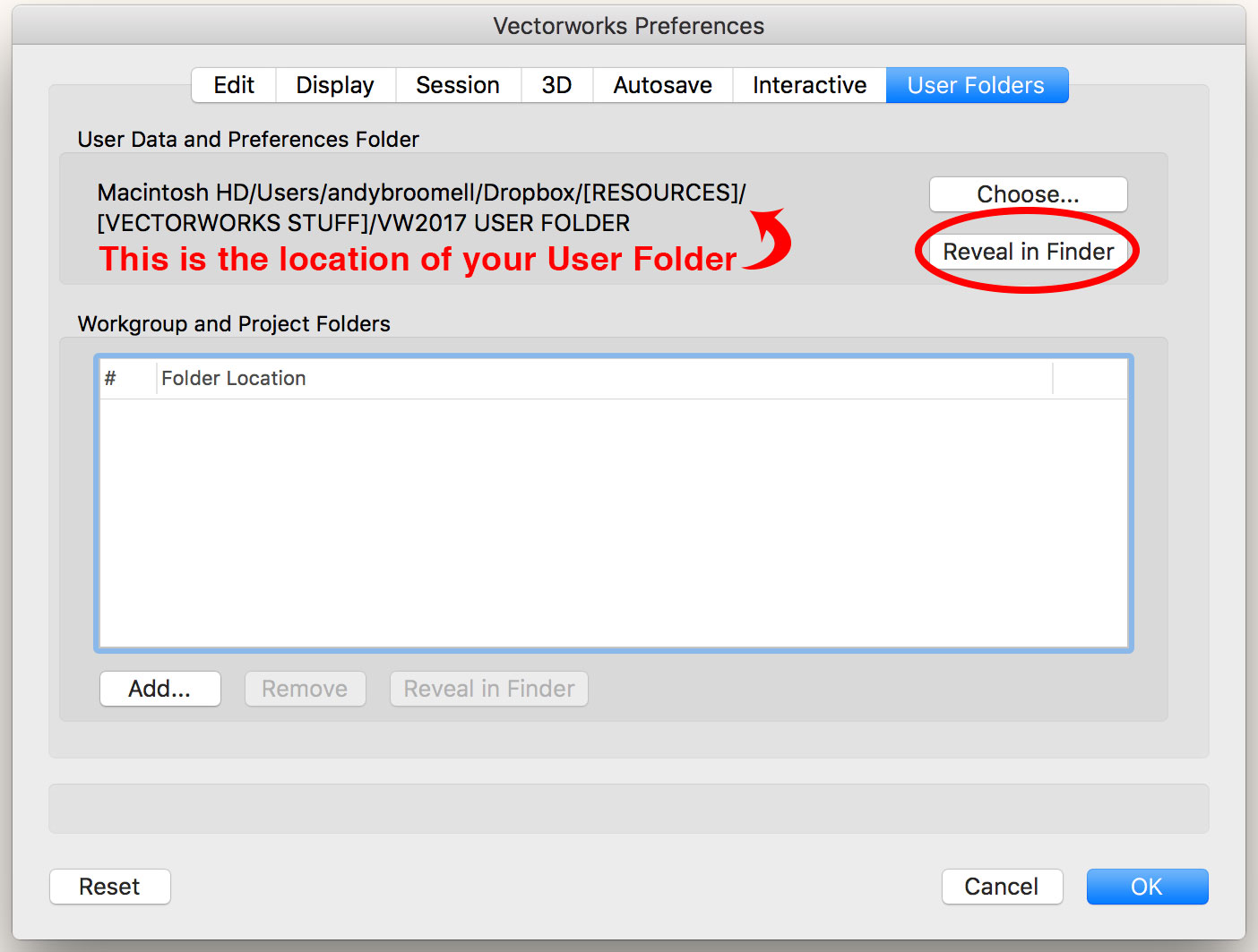
You were close with where you were looking, but instead of looking in the applications folder, it would be in your User Folder. The location of your user folder can be found within Vectorworks Preferences < User folders. It's probably different from mine... And a quick way to get to it is to click the "Reveal in Finder [or Explorer]" button on the User Folders tab.

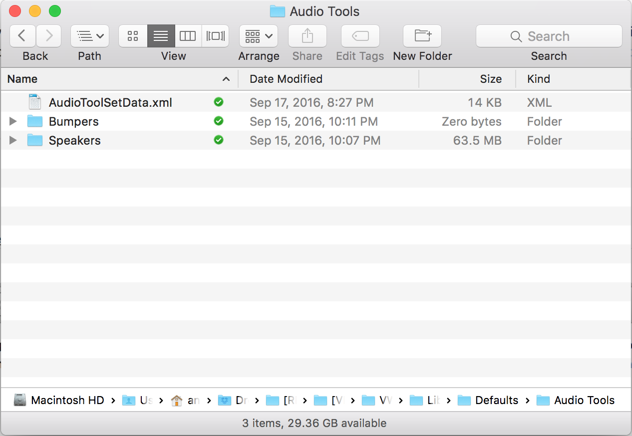
Then you can go into /Libraries/Defaults/Audio Tools and copy the XML file there. (Your User Folder has the same folder structure as the Applications folder, but contains all the files for your various customizations and preferences so that they don't get overwritten when downloading Service Packs, for example).

Someone correct me if the is wrong, but I believe that's what I did when I was transferring speaker library data from one computer to another.
-
You're not the only one, Horst. There have been a few other posts recently with people (such as myself) experiencing the same thing in 2017. It's a major issue and hopefully adding your post to the list helps make it clear that it's definitely a bug and not just a fluke or ignorance.
-
Another thing to check is to make sure you don't have two duplicates of the exact same Solid Addition on top of each other. In that case the one you're applying the texture to might be obscured by the other one.
-
In the past I've included hyperlinks to 3D models that were uploaded to SketchFab (I haven't yet tried Vectorworks' new web view functionality which might be a replacement). It worked pretty well for the fabrication shop to easily see and interact with a 3D model in addition to the 2D plans.
Out of curiosity, in your drafting (which is awesome by the way), are the elevations created with textures that are greyscale, or was the greyscale effect accomplished in some other way?
-
Not seeing that here. Could you post a screenshot or perhaps the file if you are able to?
-
As a designer for theatre and TV, I tend to never use the classes that automatically come in with pre-made objects, such as furniture and lighting fixtures. I get pretty tired of deleting "Furniture-Main" and "Electrical-Lighting" all the time. Further, these classes tend to really confuse novice users such as my students.
For some reason I'm more forgiving of the classes automatically created by the Door and Window tools, since I understand for example that "Glazing-Clear" is needed to texture the glass. But ones that come in with Symbols are annoying, personally.
-
I think the original poster is talking about working in Rotated Plan, not about rotating objects after the fact.
While I can't replicate exactly what is happening for him, I'm also encountering a bug... I can't get an angular dimension to even work on a polygon while in Rotated Plan. It only seems to "see" one side of the polygon. The same polygon dimensions fine when not in Rotated Plan.
-
47 minutes ago, JimW said:
It's a pricing issue, since we license the PDF module from Adobe directly, including that module has to come along with a price increase.
Interesting. Had no idea, but that explains it.
-
When I run into situations like this I often try right clicking the object and choosing Force Select. That will make the Layer and Class of the object Active, allowing you to edit the object. (But you should also still be aware of class visibilities and class options as Jim describes above).
-
Publish, or at least Export PDF, isn't included in Fundamentals? I would opine that being able to export a PDF is a pretty Fundamental aspect of a drafting program. It really needs to be included.
(That, and the Navigation Palette)
-
You're the best!
-
Gah, just realized I should've posted this as a separate post/request. Sorry@JimW!

-
Also note that those classes are saved as Invisible in the two Saved Views, so every time you run those views it's going to turn the classes off again.
Fastest way to fix is to select the four classes, right click, choose Visibilities, and turn them on in the Saved Views.Or if you want them off in those Saved Views, make an additional Saved View that takes you to your Groundplan with all your classes on that you want.
-
 1
1
-
-
I love the new multiple leader lines feature of Callouts.

Two thoughts:
Based on how the rest of Vectorworks functions (such as drawing Polylines or Chain Dimensions), I would expect to be able to double-click when placing the final leader line in order to complete the operation. This is not the case. Instead, double clicking inserts two leader lines on top of each other. Only hitting "Esc" finishes the operation.
The other small thing that would help with user interaction is when trying to delete a leader line, there should be blue handles on the end of each leader line, then you could click on them to delete them. Currently you just click somewhere on the line. We should still be able to click anywhere on the line - that's great - but having blue handles would help inexperienced users by providing a visual clue of what to do.
I think these two things would help unify the new functions with how the rest of Vectorworks operates.
-
I don't remember specifically, but I seem to recall an old thread discussing this issue. I feel like the root cause had something to with either A) the model being really far away from the document origin, or B) something to do with cropped/uncropped perspective, where the model was perhaps zoomed really far out when the Document Settings were set to cropped, and this was somehow affecting the view when the Document Settings were set to uncropped. Might be worth playing around with.
-
I don't seem to have this command. I have Designer, and I even checked in the workspace editor. Where is this magical tool?
-
And if this were implemented as a new tool, it would great if it could also emit light for renderings to emulate actual LED tape. All functions in one. No more creating long skinny objects with "glow" textures just to get the look of LED tape in renderings.
-
 1
1
-
-
I don't believe there's anything like this, but it's an awesome idea! Especially considering how much LED tape is being incorporated into designs these days.
-
 1
1
-
-
Here's a thread which is perhaps related? I don't think there was resolution though.
-
And just to be sure... you don't have to actually draw the 45° line unless it helps you in some way. The mirror tool will mirror across whatever vector you indicate while using the tool, regardless of whether there's a line there or not. And if you have angle snaps on, 45° should be one of the angles the mirror tol automatically snaps to (this is set up by double clicking the angle snaps button).
-
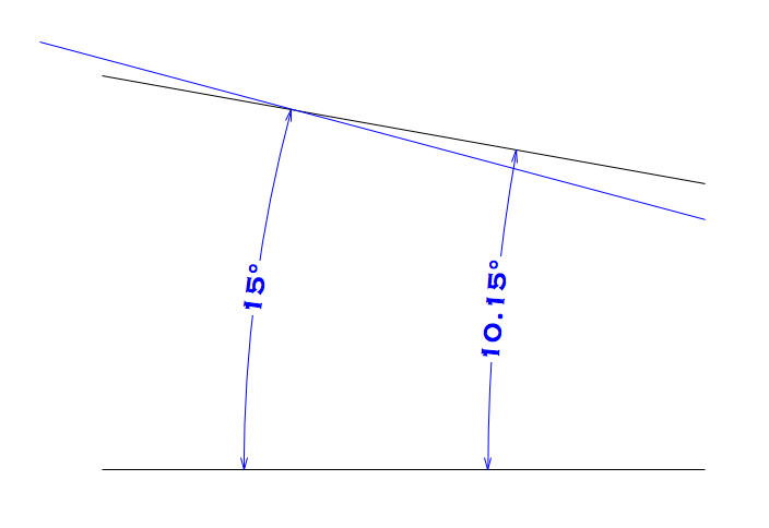
In each of your examples, one of the two dimensions isn't measuring quite what you think it's measuring. In the previous post, for example, looking at the 15° dimension, toward the top, there's a little line - the witness line. The angle of that little line is what the dimension object is actually measuring, and is presumably the angle at which the line you're measuring used to be.
Angular dimensions are tricky... if you change the angle between the two lines it's referring to, you can't just stretch the arrows to line up with your new lines... the measurement will be wrong. It's safest to delete the old dimension and re-create.
Here's a pic to help illustrate what's happening:

Another way to look at this if if you compared the "arcs" of the two dimension objects you have, they would have different center points.
Hope this helps!
-
Yeah, that might be a good workaround for some people, thank you.
But I have hundreds of old project files, all of which are very large and across many folders, and I don't necessarily want them as "Favorites". It'd be nice to access them quickly on an as-needed basis without worrying about what version they were created in.


Replace symbol with duplicate
in Wishlist - Feature and Content Requests
Posted
True! I hadn't thought about it this way. I often want to replace a Symbol with one that has a very similar name and is probably right next to the current symbol.