


DomC
-
Posts
605 -
Joined
-
Last visited
Content Type
Profiles
Forums
Events
Articles
Marionette
Store
File Comments posted by DomC
-
-

Sure
The Script needed a little Updates for 2019. Cause the Path Handling in 2019 is better than in 2017/2018 I had to delete some lines.
-
 1
1
-
-
Attached an Example with Spaces (Name "Flur").
The original Example has the limitation, that some values of viewport position (function node and vector input) of are in mm instead of document units. I corrected this in the attached VWX example with spaces.
The rotation task is not implemented. But the rest works for your scenario I think.
-
Hello
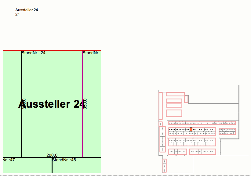
I try to push this somewhere between. As far as the criteria is matching (search for every space with Flur in the name or similar) It will push all such Spaces into the script. It would need the following adjustments:
1. Read Layer name of Space to make this layer visible in the viewport (easy task)
2. Read Room Infos to name layout with the room number, room and layer name etc. (easy task)
3. The project seems to be directed to north. So maybe you want to turn the viewports by this angle (maybe all the same angle?) or by the angle of the text label? (medium task, could take some hours to implement the angle)
4. In the existing Example the room would be marked with a rectangle around the bounding box of the room. For your scenario it would be better, to use a parallel polygon to the room polygon (particularly it the room is rotated as yours) (medium task)
So it could take some hours to fit the example for your explicit usecase. Always this scripts have to perfect from experience. More perfect than any other tools because users can see, that every little limitation can be eleminated by a custom workflow script.
Have all parts of the building the same angle? So what is about beeing the boss in the project and make your own angle of the building? It is a common workflow to not north the building and not use a international origin. You could layer-link the building in a georefered overview plan if it is necessary. Just a stupid idea. It is not possible to command a project angle and project origin in every project. But it would save time.
-
1
-
-
Hi
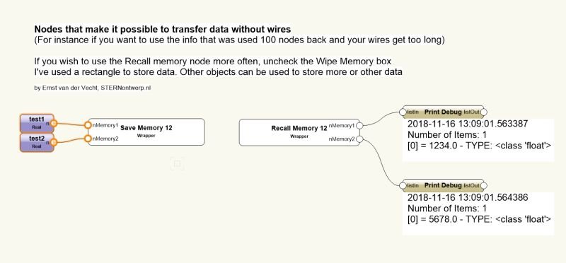
I like the wish of transporting dada without wires. I can see many issues with your approach and would not use that.
It maybe would be better to cache data on an external ressource or on the recall wrapper itself. You could name the recall wrapper an send data from the save wrapper to a record format which will be attached to the recall wrapper.
I am working on a cache node, which cache everything that is running through a wire. That would be very good for caching data of a big network which need a long time to calculate and would speed up workflows.
You could save global variables as well, which would be the technicall solution for wireless data. But if you load a global variable before it was stored it could
-
Thank for competent Feedback.
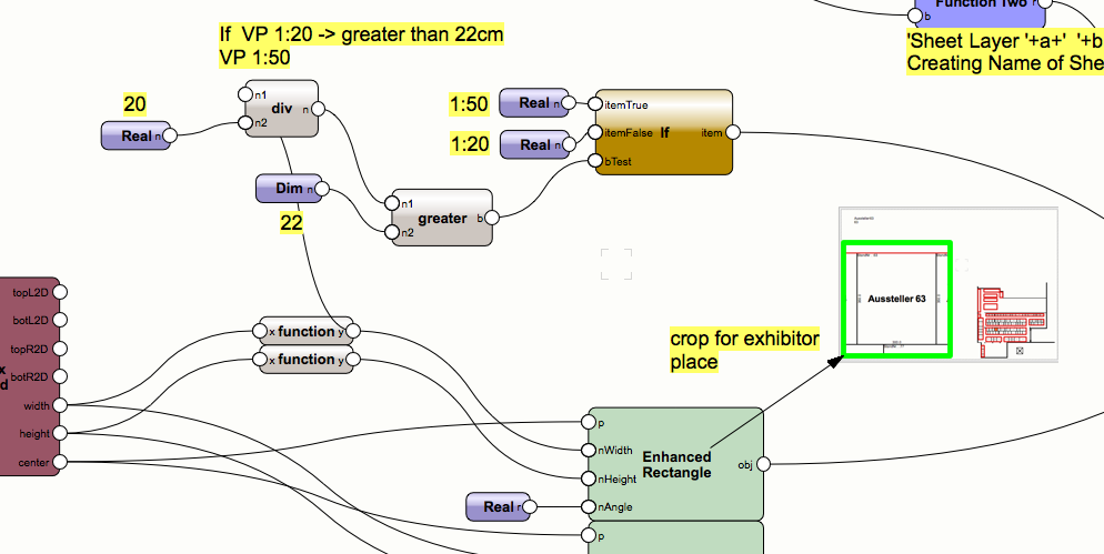
QuoteIf the width of the 2D BBox > 400: the scale of the viewport could be 1:50 instead of 1:20, or have a varying scale depending on the width.
for sure, this would be a nice refining. 1:50 / 1:20 step could be made like this:
 Quote
QuotesLinvis is described as grey instead of invisible (and I think it would be easier on the eye if the standplaenung-layer was grey in the overview viewport)
True Thanks. I focussed time investment on getting section Viewports on my layouts (which failed and I dropped this for now) instead of maturing the vp nodes.
To have a complete set of VP nodes there also a class visibility would be needed.
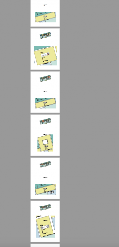
Updated the File. By the way, thats just a study. Maybe it would more practical to just duplicate a default layout with placeholders for vp and text fields. So it would be scalable on new situations very fast.

-
Hi
Looks somehow interesting. Is this just the exercise or did you maybe missed pasting the marionette network of the solution?
Regards
Dom
-
1. In your original File-Download none of the Room_IDs have some content. Now you found the right field the m2 is visible, right?
2. If I copy the original Marionette in your original File, enter a room id and link room id to the marionette (same room id), everything works as described.
3. You created a Marionette, which is completely different to the original script. You don't use a symbol you just place text objects. If you created a new script maybe a Thread in the forum would be the right place to discuss this.
-
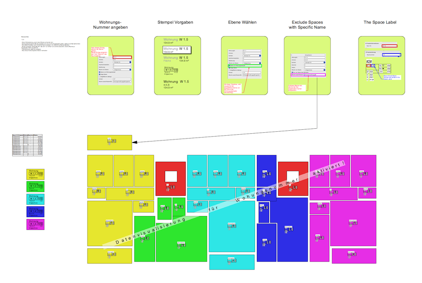
It's point 1 from my list above. This stamp needs the Field "Raum ID" which is an empty field in all your spaces. "Raum ID" is not the same as "Raum Nummer".
-
Can't reproduce that with the information you delivered.
1. Maybe your stamp just loss connection to the rooms, Room ID changed etc. Does your spaces have the value Room ID as Example "W.1.1" like in my example?
Changing scale, rotating or moving maybe just update your stamp and it shows the truth (stamp has no link to rooms)
3. Does my example work? If yes, what you made different?
4. Maybe you created a hybrid symbol and symbol text is 3D or something like this?
5. Maybe there is an issue with your document units show or hide or did you created a custom area unit? The record field is a number if you feed this number with a string (5 qm instead of 5.0) it will maybe fail. Try to make a Text field in the record format could fix if this was the issue.
6. Line Spacing
The tool works like a symbol with text, linked to record. So you can test that with a simple symbol. Your appartment area stamp will look like your symbol. If it looks wrong, your symbol also looks wrong. Maybe unfix textfield width in your symbols.
7. Upload your Example ... it's hard to help without that.
-
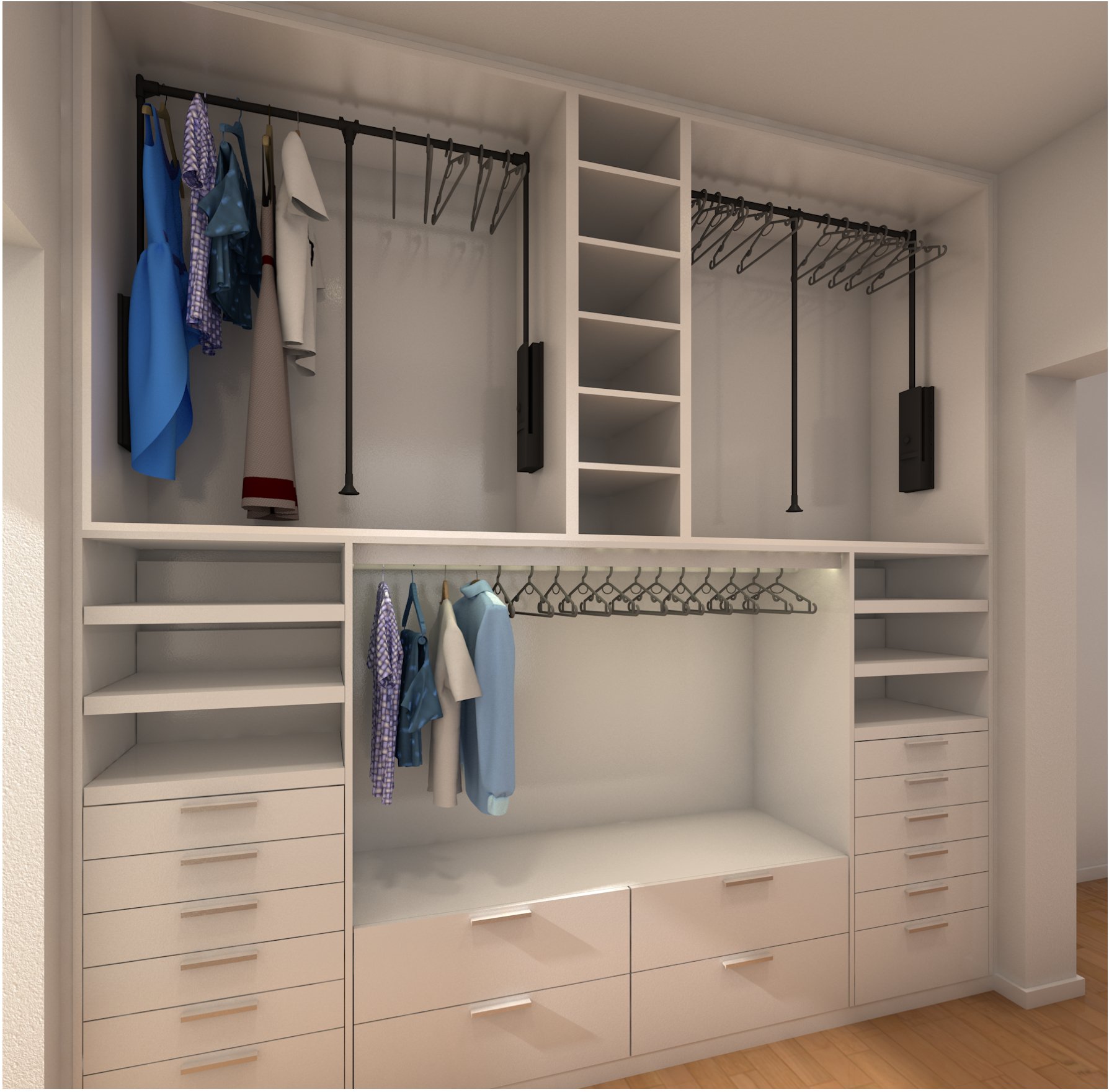
Puohh
Cool example ... thanks for sharing, love that.


-
1
-
-
Hi @ccsw
Thank you very much for that input. There is a build in function "Marionette.Is2DObject (obj)". This checkes if an Object is 3D or if an Object is 2D. 2D and 3D are handled with other functions. At the release time of the node (maybe still, I did noch checked that) this function did noch correctly sort 2D and 3D Objects. So I think I just hardcoded the line "Is_2D_Obj = True #Marionette.Is2DObject (obj)" (It means that the node always handle objects as 2D)
The line should be correctly (if the marionette function was correctly) "Is_2D_Obj = Marionette.Is2DObject (obj)". A new Version of the node is uploaded.
-
2
-
-
The Attached Example (Copy of the original file but with different Pillow download path) works with VW 2017 Mac Version (Windows not tested, but it also should work).
-
A Workaround for 2018 Macintosh
1. Unzip and copy the attached Folder into the user folder (Vectorworks Preferences -> User Folder -> Revieal in Finder) into the Folder "Python Externals"
2. You can use with all scripts that uses Pillow. Also the above Script will work.
-
1
-
-
I got it to work on Windows but not on Mac. I was not able to get a working url for Pillow with Vectorworks 2018 on Macintosh. Reported a Bug for VW 2018 but I am not sure, if this is A Vectorworks issue other modules can be installed without any issues.
Would be glad to got a solution for Pillow on Macintosh. This is the only module for image processing i found. Other image modules also needs pillow as an image library.
-
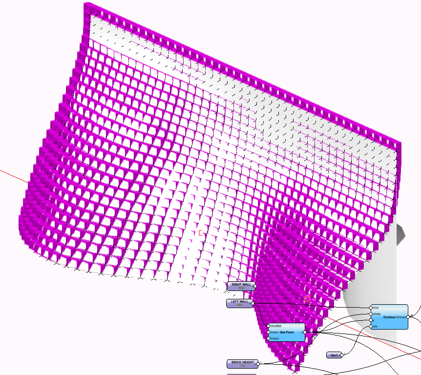
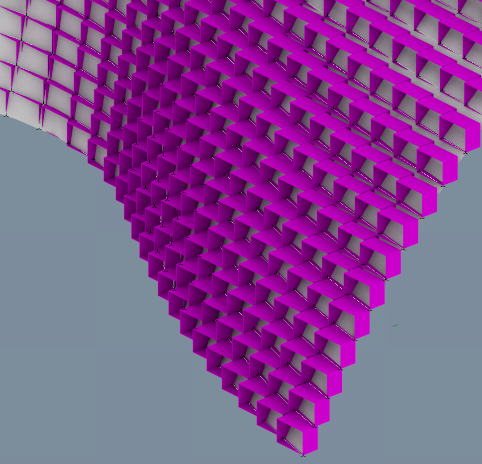
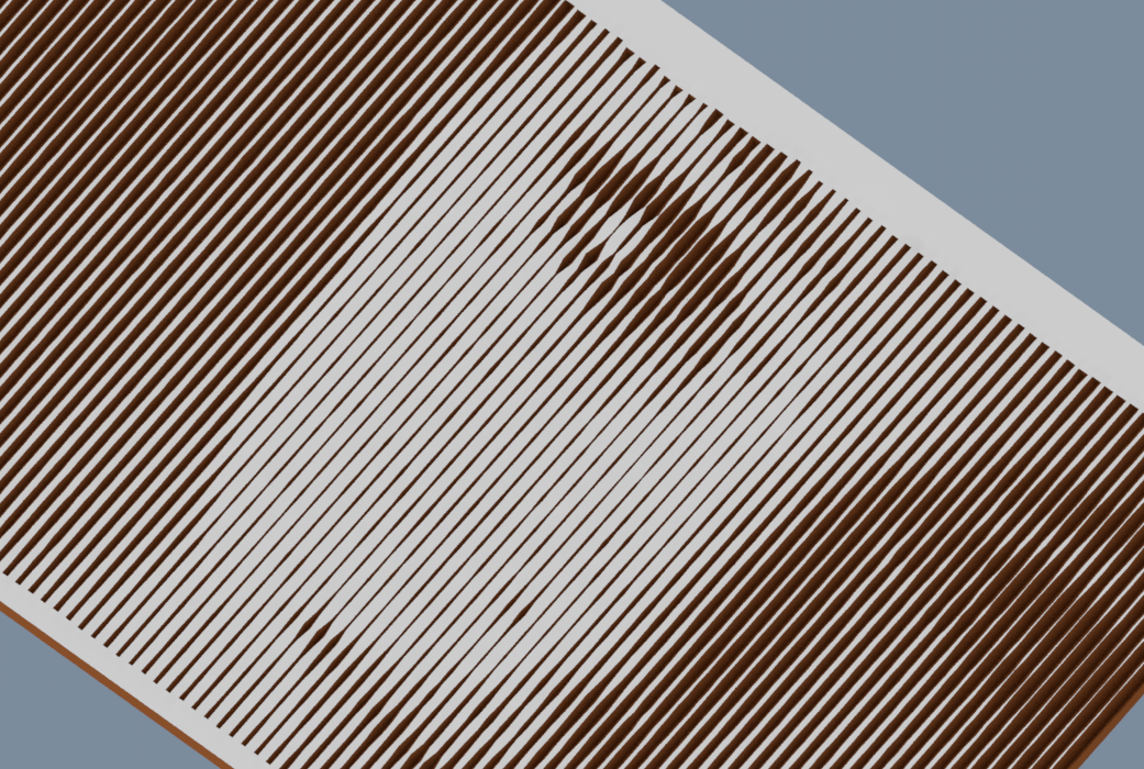
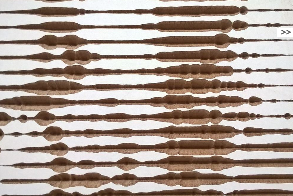
Great @Bertf
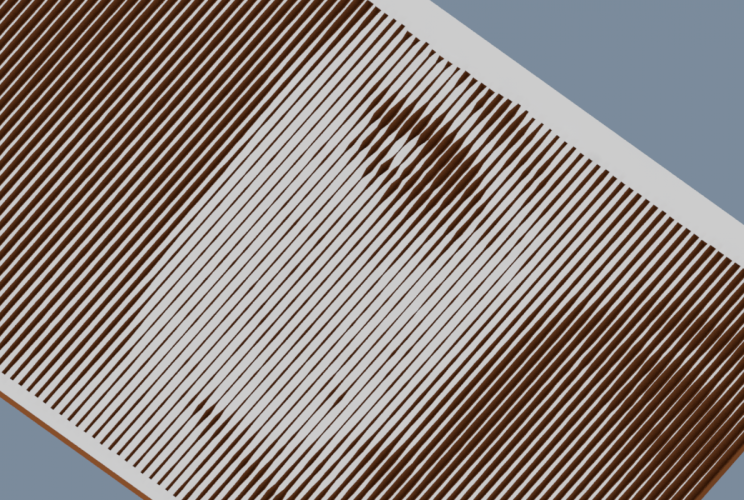
Your Screenshots shows a contour in x direction with different z values. My screenshot (found out now) shows simple Drillings (v-fräser). But the x-distance is 10x of the y distance. Thats why we can see lines.
My screenshot shows the variant of 3D contour with a v-fräser. Too bad I have no place for a CNC-Milling machine.
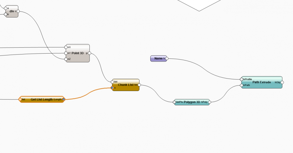
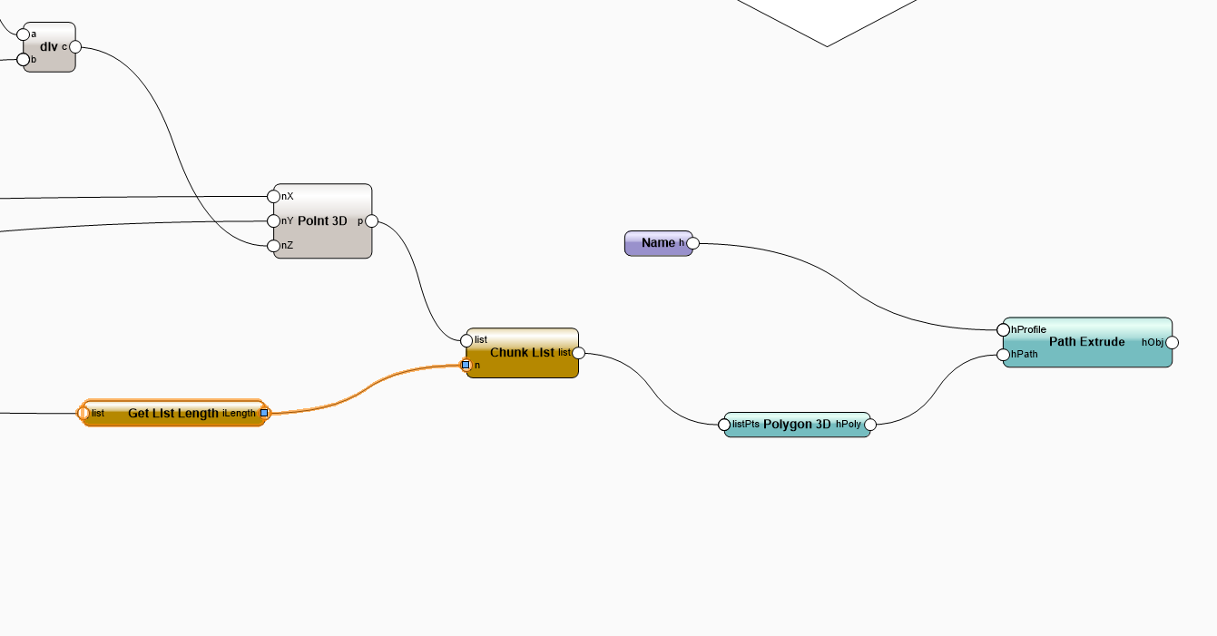
Can be done easy with the chunk node (to get single polygons for every line). EAP created for visualisation.

-
This is Great Bert
Have you also tried to mill in a line structure? and connect the Points?
Should this work, if I had a 3D Polygon. And can convert this to a 3D Path with the DXF Post-Prozessor?

-
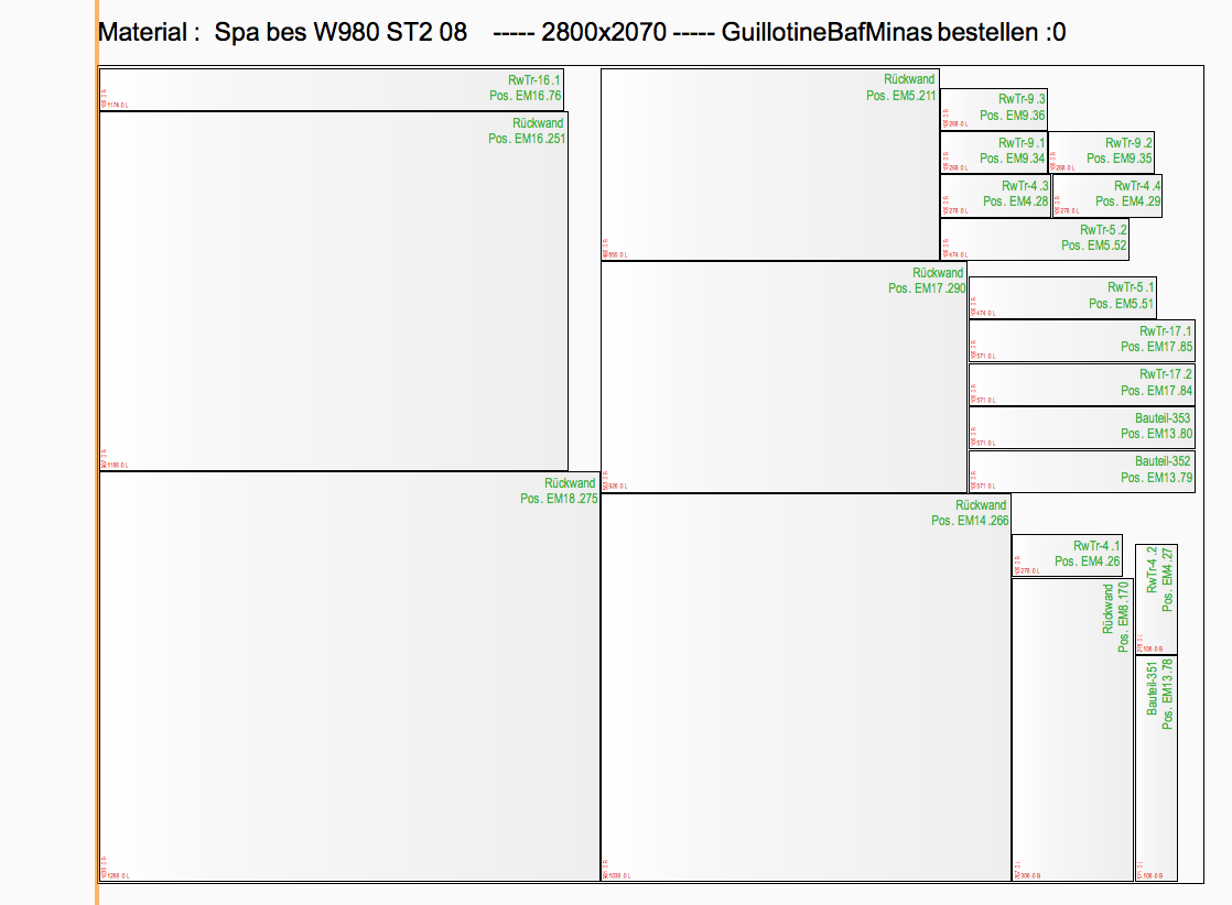
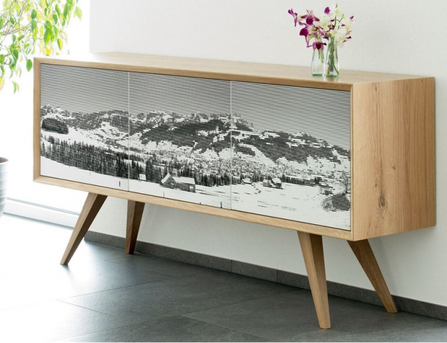
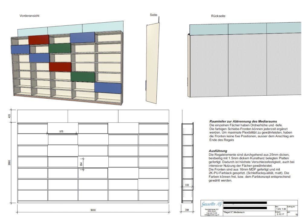
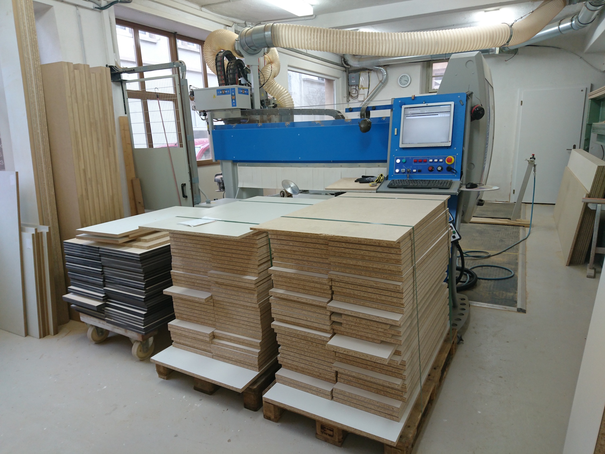
Some Screenshots of a carpenter who uses this for cutting arrangements.
So great to see, how other people uses those technology (and days of work) to improve their workflows. http://www.garzotto-ag.ch/
Screenshots attached

-
Another great Example, that shows, how potent the Integration of Marionette Objects is, to customize (Nothing other that will be the logical result of Industry 4.0) core features.
I would like to see that Feature for windows and other core plugins!
Sure, VW Inc. had to optimize some details to get a good enough marionette-quality (duplication of PIOs takes too much time) for integration capability in core PIOs
-
1
-
-
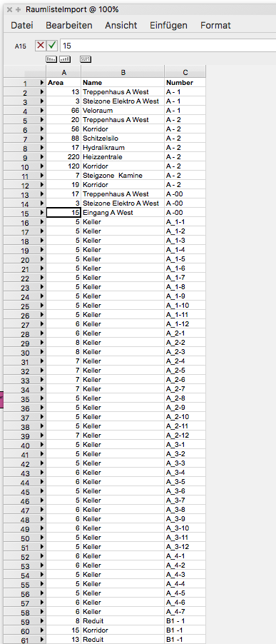
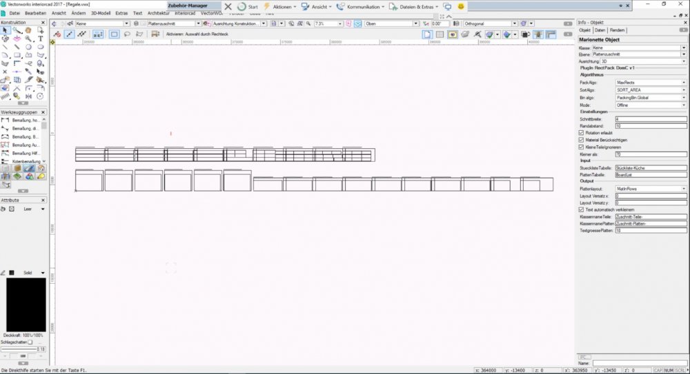
Please consider, that the the script takes the area column and calculate the square with that. If you have a language settings with comma instead of points for decimal seperator, the calculation will fail. Use points as decimal separator or eliminate decimal places in your list.


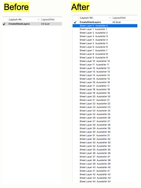
Automated Layout
in Marionette - Nodes
Posted
Hi
Use "Print Debug" to see, what's coming in the "Create Layer" Node. If you have always the same layer name (input) or the same layer handle (output), all your viewports will created on the same sheet layer.