Search the Community
Showing results for tags 'structural'.
Found 5 results
-

Structural Member usability improvements
LarryO posted a question in Wishlist - Feature and Content Requests
1. Needs to have length shown and alterable in the OI palette like any other linear construct. 2. Needs to have the Axis alignment in the OI using a radio button concept similar to that which is implemented for rectangles. The image used in the geometry settings window is well suited for the purpose. 3. The Angle profile should be rotated 180° so the top axis default alignment is to a leg face, not air. Most structural elements are installed utilizing Top of Steel elevation concepts. 4. There needs to be an edit mode to permit addition components and subtraction subtraction components. The insertion of one or more creating selection node(s) which can be dragged outside of the edit mode to relocate the component's position along the member's axis. I would suggest that the axis the components nodes snap to be the top centre axis. These components being 3d symbols or possibly 3d plugin geometry. The former is suited for adding stiffener plates, saddles and connection plates or angles among other things. The latter might be suitable for tools that arrange holes in the flanges or the web or for coping ends of Wide flanges. The ability of a component to remain either plumb to the layer or perpendicular to the axis of sloped members is also a consideration. 5. Being able to snap to those nodes with dimensioning tools. 6. The ability to lock in a slope angle when altering the length of the member is also valuable for sloping steel roof and canopy structures; As is being able to set an angle as an alternative to setting an end elevation. 7. Component edit mode being accessible from the resource palette similar to how symbols are handled. That way all beams can be seen and their member IDs are also available for editing. Beams when placed in a plan layout may start out as being multiple instances like symbols but may need to be duplicated and edited as the development process continues. 8. This is a very useful one and should be a wishlist item of its own. Have a Viewport type which can generate a beam or symbol from the definition. (for placement on sheet layers) Talking 3d here and all the various views that the basic Viewport can display. This creates an easy means to annotate each beam and symbol. Avoids possibly hundreds of classes and or layers being required to control visibility. The current process of laying out beams for a structure is still required but all the layout of each beam would be tremendously simplified and can utilize templates for annotation. One only needs to remember that all symbols and beams be created at their internal origin for best functionality. 9. Having the Viewport mentioned above being able to tap into the member id and or symbol name to facilitate automatic labeling. Or would that be the other way around where labels in the Viewport tap into those ids and names? 10. Profile size should be editable as a pull down at the root level of the OI, not embedded behind a shape selection button. 11. The technical data that the individual members currently provide should be displayed in the OI or accessible from the OI via a button. Weight characteristics for the basic member is a useful piece of data that is currently not provided. 12. Custom sizes as currently provided in the individual member tools is also useful for those sizes that are not in the predefined setting. This is helpful when using bar angle, bar channel and some tubing sizes which are currently not in the selection lists.- 16 replies
-
- 12
-

-
- structural
- steel
- (and 2 more)
-
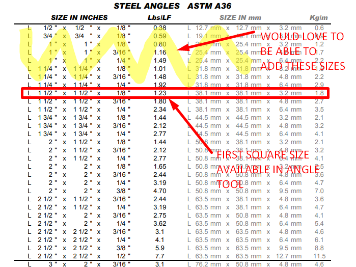
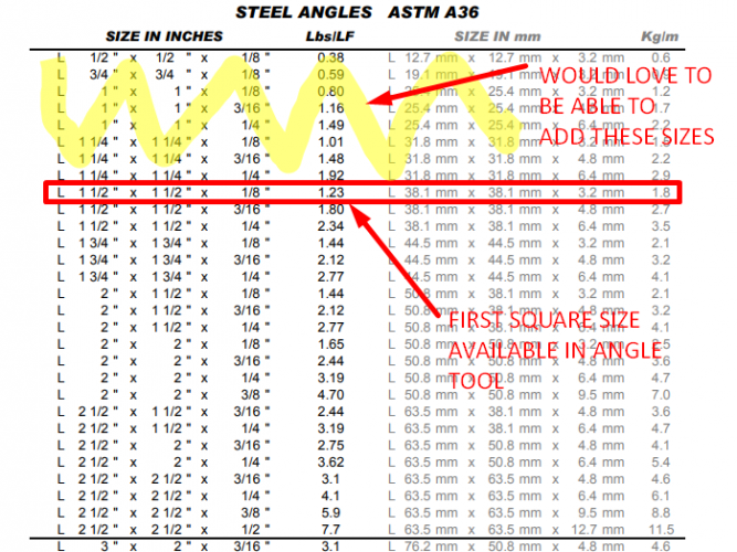
I was wondering if there is a way to add Sizes or Series to the Structural Shapes tools already present in the Detailing toolset within vectorworks. Our issue is that the Angle shapes don't include many of the smaller sizes that are common. It only goes down to 1.5x1.5.0.125 and we would love to be able to use it to quickly model shapes as small as 0.5X0.5X0.125. The chart of standard ASTM A36 steel angle sizes below shows where VW standard sizes start and what we are missing on the small size end.
-
I would like to know how I can insert new standards in the Structural Member category. How do I enter new usages / Member Types / New Shapes? I can not locate in the root of the software where I can put this new information, neither the own settings that comes with VectorWorks. I’m using Vectorworks 2017 SP3
-
Hello! I'm in trouble with wall style and wall framer. I did set a style of my wall (ParetePlatformFrame) and I'm unable to match the interior component (PlatformFrame) to a frame generated by Wall framer. The control offset is ok... It seems that the Wall framer start to the middle axes instead of the control line, as shown by the dashed red line... You could try by yourself, deleting my wall and drawing a new. Is there a way to do that? Here's the file... Thank you L. PS Of course, I could set a Wall, with a proper offset, just for structure, but it's not what I do expect in 2017... :-)) PlatformFrame.vwx
-
Hello! I think I need a complete tutorial about the news structural member tool, because there are things that seems doesn't works. I do place four columns, then I try to draw the beams, but it draw them at the bottoms of columns instead of the head. I do set the proper elevation in the dialog box, but it's the same... So, the build has some problems to fix (OXS - 327801) (to let auto join works, I have to deselect and then select it again - just for example) or I do somethings wrong and then I need some tutorial. Thank you L.
- 12 replies
-
- 1
-
-
- smt
- structural
- (and 2 more)