Search the Community
Showing results for tags 'line types'.
Found 4 results
-
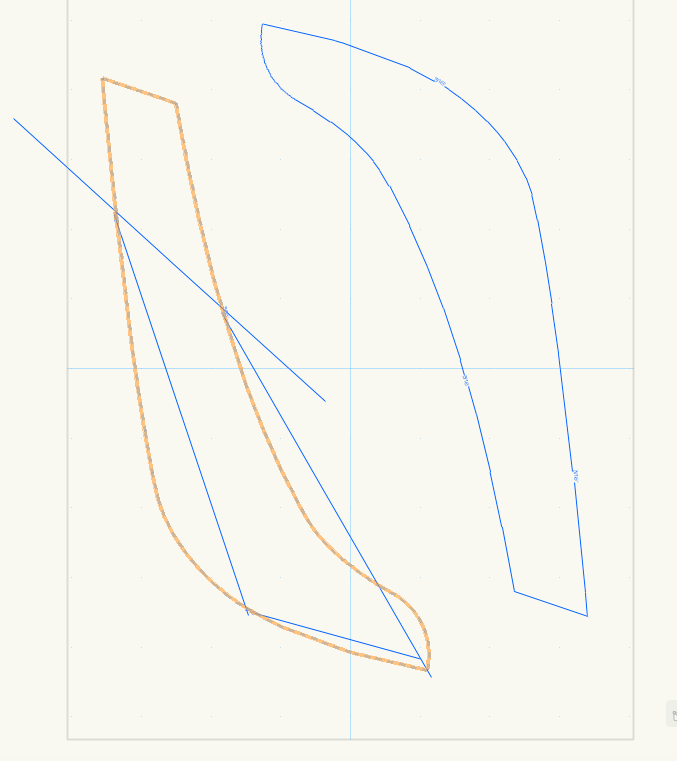
The enclosed image shows the same shape, the one on the left is a polyline, the one on the right is a polygon. Both have the exact same complex line type showing in blue. I am hovering over the polyline on the left to show the orange shape. The complex line type on the polyline displays as a series of the line definitions situated around the polyline, they are straight and do not follow the shape of the polyline. I.e. it is completely unusable. I can convert it to a polygon, but this loses information and makes it less editable. Is this a known issue? Is it intentional?
-
I draw my existing conditions and use 2d symbols for things like sinks, vanities, etc... The symbol is originally created on the 'None" class. I set the symbol line type to "by class" but when I move it to the demo class the line type doesn't change. In order to get the line type to change I have to enter the symbol and change the line type of each of the objects contained within the symbol to "by class" and put all of those objects within the symbol on the demolition class. That will work although, it then changes all of my existing symbols (which are not to be on the demolition plan). How do you accomplish this without having to create a new demolition symbol for each symbol? Thanks, Derek
-
Hi all, Is there a way to scale a dashed line in a easy way? AFAIK the only way to do it is via Advance Viewport Properties: Line Type Scale. Cheers, Juan
-
Is there a straight forward way to set up VW plan from a 3d model whereby VW draws lines as per drafting conventions (assuming of course these are universal..?): Hidden objects below plan cut (eg. under counter tops): dashed lines Above plan cut (eg. ceilings): dash-dot Cut plane: thick lines Visible beyond view plane: solid, but not so thick as cut plane