Search the Community
Showing results for tags 'landscape architecture'.
-
Hi All, after much pain and suffering trying to find out how to do it I thought I would share how I align my VWs models with lead consultant's (Architect's) Revit model. This assumes the following: You are not lead consultant so you haven't created the shared project coordinates yourself. You are not lead consultant so you are contractually obliged by your client to align your model with the lead not the other way round You are not the BIM coordinator and have received a useless Revit centric BEP. You understand the difference between User Origin and Internal Origin in VW. You understand the importance of modelling close to the Internal Origin to avoid glitches You are doing this before you start modelling. While the steps are the same for after you've modelled, changing the Internal Origin is not advised unless you are being held at gun point by the client. All your sheet layer viewports will be messed up and need reworking. Key message: you need to change the coordinate of your Internal Origin to match the Internal Origin of Revit (which should also be the shared project coordinate). Forget User Origin for now. Steps: 1. Ask the lead consultant (or whoever has set the shared project coordinates) for the Northing and Easting coordinate (relative to British National Grid or your local system) for the Revit Internal Origin. Revit does not recognise your VW User Origin so changing the User Origin won't help align models. 2. Firstly make sure your Vectorworks Document is set to your local coordinate system: File> Document Settings>Georeferencing>tick 'adjust origin and orientation of georeferenced data to match document coordinates' (not sure if necessary). in this window check 'Use an EPSG code or CRS name' Click Lookup and find EPSG 27700 / CRS name: OSB 1936 / British National Grid (or your local system). I had to Google this. Close Document Georeferencing window. This makes sure you are in the correct overall system for Northing and Easting coords (if in the UK). 3. If you now go to your Geolocate tools and select 'Geolocate' while looking near your Internal Origin VW will download and display a satellite image of the world at your Internal Origin. For me this was default right next to the Greenwich Observatory in London. You want your project site to appear here instead in exactly the right location to the mm so... 4. De-select the Geolocate tool (this step was just to demonstrate the location of your Internal Origin in VW relative to the real world). 5. Draw a circle anywhere and type into its centre point properties the Northing and Easting of the Revit Internal Origin. 6. Select the Geolocate tool again and click on the centre of the circle. You get a warning that this changes the Internal Origin of VW but accept it anyway. 7. Now your Internal Origin is the same as the Revit Internal Origin and should be in the 'real' site location. Assuming the Revit user knows what they are doing. 8. Select the Geolocate tool again and hover over the Internal Origin - it should download the satellite image of the real location which should be your site. This step is just to check everything has worked and is not necessary. 9. Head to Tools>Origin>User Origin> check 'Set User Origin to Match the Georeferencing coordinate system'. This just makes sure your User Origin is reset and providing you real coordinates if you have been moving it in the past. 10. Celebrate. 11. if the Revit using lead consultant has also rotated their Internal Origin I am pretty sure you can do so too by heading back into File> Document Settings>Georeferencing and changing the angle to true north here. Edit: the Geolocate tool has a setting option to rotate the Internal Origin. I don't know if it is possible to also change the Z height of the VW Internal Origin but it is less important. Revit seems to struggle with moving IFC models into position manually in the X Y plane but moving it in the Z axis is a relatively simple task and the Revit using lead consultant shouldn't break a sweat over it. I only share my model as IFCs to Revit as you get control over what to export. It is important to make sure your User Origin is set to Northing and Easting 0,0. This ensures you get proper coordinates from your model and you import references in the correct position but also for file sharing across multiple softwares. While Revit only recognises Internal Origin, Autocad and Navisworks seem to use your User Origin when importing. Hope that saves some of you your sanity. Jack
- 11 replies
-
- 9
-

-

-
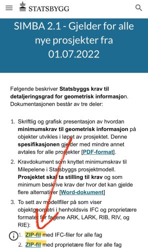
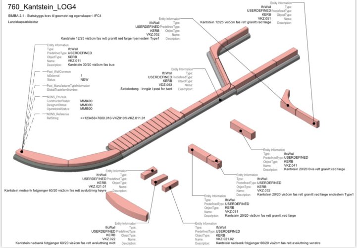
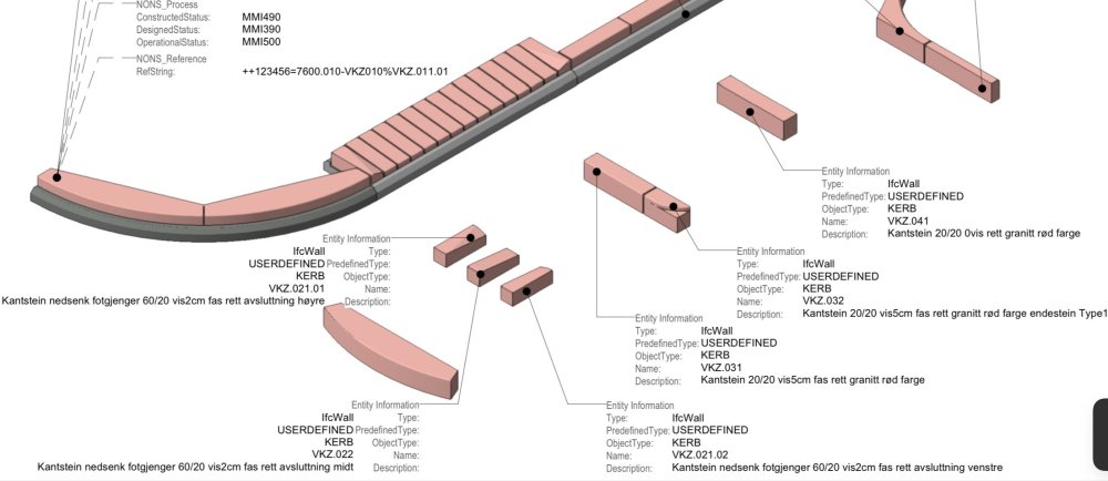
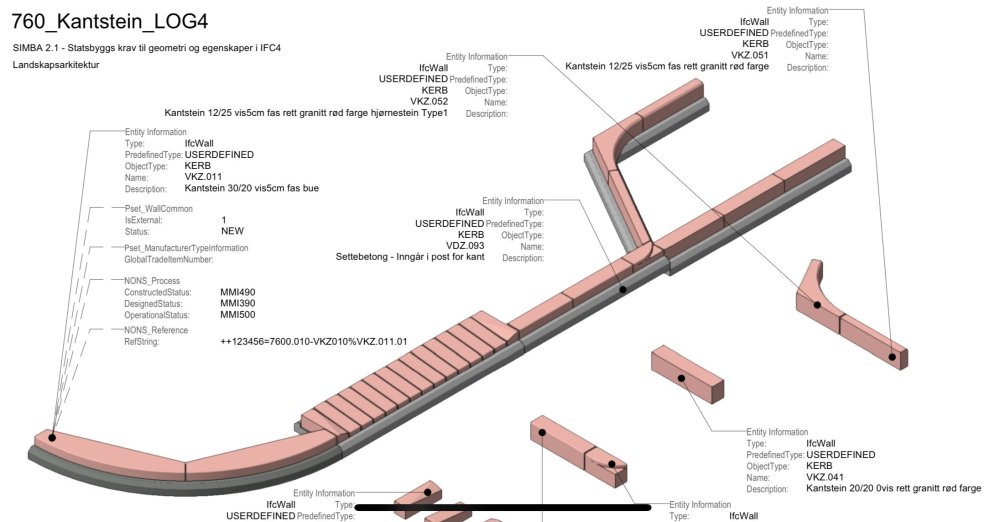
When will Vectorworks come with the possibility to test/use export to IFC4.3/ IFC4x3 which is adapted to outdoor design? Autodesk has included IFC4.3 in both Revit and Civil3D. Transport projects in Scandinavia use Trimble Quadri and they also have access to IFC4.3. Several projects we are involved in are considering the use of IFC4.3 and then we should also be able to deliver on this from Vectorworks. https://bimcorner.com/key-changes-in-ifc-schema-shaping-openbim-for-infrastructure/ https://bimcorner.com/ifc-4-3-on-construction-site/ https://bimcorner.com/spatial-breakdown-structure-in-ifc-4-3/ Statsbygg the Norwegian government’s building commissioner has completed solution for Ifc4.2 (4.3) for Landscape Architecture. Download zip files for IFC and proprietary files, Vectorworks. https://sites.google.com/view/simba-bim-krav/simba-2-1-gjeldende/simba-2-1-geometrisk-informasjon-detaljeringsgrad
-
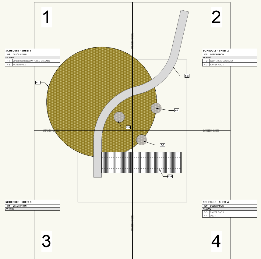
Alright VW Friends, we need some help troubleshooting a particular workflow that has become problematic. The challenge... How do you create a legend that is specific to the items being identified by Data Tags within a given viewport using Records and Data Tags? Because this is a technical question, I'm going to have to get into the weeds a little with our particular challenge. We have grown particularly fond of using specific custom record formats, coupled with data tags, to more easily manage callouts/keynotes in a drawing. It is very easy to create "Master" legends that summarize specific information in a variety of ways for all "similar" objects across a drawing/file using isolation techniques like class, record format, layer, etc. The difficulty lies in using the same record information to query a subset of those objects that appear in specific viewports, and exclude those that do not appear. In the landscape architecture world, it is not uncommon to have projects where improvements span multiple sheets and/or viewports. These are typically separated by match lines. In the image below, we have a simplified scenario where improvements are divided into (4) different viewports... Notice that there are (7) objects in the drawing, each attached with the same record format and identified using the fields ID# and DESCRIPTION. The large circle, which is actually clipped into two objects by the serpentine "sidewalk", exists in all (4) of the viewports. In the attachments to this post are exports of each sheet layer as an individual image where it is possible to see that data tags, placed in the annotations of each viewport, can easily identify the objects by their ID#. I've also attached the VW file used to create this example. QUESTION: Now...how do you populate each of the unique worksheets with the items identified by the data tags (or even those that are clearly visible in the viewport)? The goal, given this example, is to provide legends (worksheets) that should include items as follows: Sheet 1 P-1 P-2 P-3 Sheet 2 P-1 P-2 P-3 Sheet 3 P-1 P-2 P-4 Sheet 4 P-1 P-3 P-4 You will also notice that the legends (actually worksheets in VW) do not correctly indicate the objects that are visible...or even those that have Data Tags. Sheet 3 doesn't include any...this is because our methodology, up until now, has been to use the Location...is within criteria in each unique worksheet to query the objects that fall within shapes that represent each viewport (gray dashed squares). For example, Schedule - Sheet 1, is querying ALL objects with 1) Record attached, and 2) Location is within Shape 01 Schedule - Sheet 2, is querying ALL objects with 1) Record attached, and 2) Location is within Shape 02 Schedule - Sheet 3, is querying ALL objects with 1) Record attached, and 2) Location is within Shape 03 Schedule - Sheet 4, is querying ALL objects with 1) Record attached, and 2) Location is within Shape 04 The problem arises because the Location...is within criteria only successfully queries objects where the Center Point falls within the identified Object. This is why Sheet 3 doesn't return anything but should include P-1, P-2, and P-4. There are technically two P-1s in this viewport because the large circle is being clipped by the serpentine path, but both of their respective center points fall outside of the Shape 03. Similarly the center of P-2, the serpentine sidewalk, is in Shape 02; and the center of P-4, the rectangular deck is in Shape 04. We have various workarounds to try and remedy this situation using this "Location Based" workflow, but they are needlessly complicated and result in errors that are difficult to track down and timely to troubleshoot. They are not worth mentioning and the goal of this post is to try and find another, better way. It seams to me that a solution might already exist, but as someone who knows VW quite well, I have struggled for a long time to figure out what it could be. A solution that does work, but we want to avoid at ALL costs is...clipping the objects by their specific viewports so that each object is firmly located "within" each specific viewport. This is a terrible method because it destroys all sense of greater geometry, creates more opportunity for error, and does not facilitate easy revisions if geometries require editing. I could think of two solutions, but both are NOT CURRENT functionality within VW that I am aware of: Query Data Tags and Report Their Linkage - The problem with our workflow is that it is querying the objects...not the data tags. It is possible to place the correct data tags on each sheet, regardless of where the object's center is, and it is possible to build a query/report of specific data tags on a given sheet layer. What IS NOT possible is to link the query of a data tag to the data of the object it is tagging. Intersection Criteria - If, instead of the only location based criteria being available being either "Is Within" or "Is Not Within", potentially adding an "Intersects With" option could mitigate the issue of an objects center point driving the query results. This is functionality common to many GIS software programs and it is one that I think could benefit a lot of use cases... Calling all helpful users to help figure out the best workflow for this @Eric Gilbey, PLA @bgoff @rowbear97 @Tony Kostreski @Vlado @Pat Stanford VW Sheet Legends and Data Tags.vwx
- 9 replies
-
- landscape architecture
- matchline
-
(and 3 more)
Tagged with:
-
Hi guys, I've created a custom formatted worksheet for our plant schedules that is just in a .vwx file on my desktop. I want everyone in my office to be able to have access to it via ourVW Workgroup. Is there a way for me to export just the worksheet into the Workgroup or do I maybe have to save the file it's in as a .sta template and access the worksheet in the Resource Manager form there? Any help is appreciated 🙂 Thanks!
- 1 reply
-
- vw landmark 2019
- landscape architecture
-
(and 3 more)
Tagged with:
-
We often work directly with civil engineers who are stuck in Autodesks Civil3D world. I know that the suite of tools they use to model terrain, roads, and sites isn't too far off from Vectorworks site models and site modifiers. Everytime we try to collaborate with Civil3D users, we have to dumb the data down to a base .dwg and in doing so we lose a lot of what Civil3D calls AeCc objects. These have a lot of information included that is useful, including the basic graphic attributes and operability. It would be awesome if the import commands for .dwgs or whatever file type is best can better aide the interchange between the two programs! And for that matter, the interchange should work both ways. I should be able to send files with objects that a Civil3D user can easily use and manipulate!
- 4 replies
-
- landscape architecture
- site model
-
(and 4 more)
Tagged with:


