


C. Andrew Dunning
-
Posts
1,174 -
Joined
Content Type
Profiles
Forums
Events
Articles
Marionette
Store
Posts posted by C. Andrew Dunning
-
-
23 hours ago, Ben3B said:
How can I use equipment list with led VS4 ?
VS4 doesn't appear in spotlight pref inventory tab...
At this time, the VW inventory system doesn’t recognize 3rd-party objects (including ours). That being said, as @JustinVH mentioned, @Scott C. Parker might know of a development that hasn't hit my radar, yet.
-
40 minutes ago, Joe Golden ENT said:
Thanks for this, it fixed an issue I was having with the Softgoods tool.
Great!!!
-
Greetings from Music City, USA!
Yesterday we released updates for all of our tools. While several of the tools exhibit evident refinement and bug fixes, the changes for others are "under-the-hood." For example, there is a new VideoScreen 4 Image Picker dialog and speaker and bumper Symbols can now contain embedded Symbols.
Most of the adjustments are direct responses to user input...
MANY thanks to the folks at the Mothership for sharing bug-reports and counsel!
See our Plug-Ins page for more info.
-
 2
2
-
-
Is this in Library/Catalog mode or Symbol mode?
Does this happen w. the Preferences dialog or w. an already-placed object?
Does VW freeze or does it simply take a really long time to re-generate the object?
If Symbol mode, how intricate is the given Symbol?
-
2
-
-
2 hours ago, jameslye said:
The ability to add Custom Speaker yokes to custom speaker symbols
As of the September release, the Landru Design version of the audio tools includes this feature.
-
44 minutes ago, pmorberg said:
Hi,
I have a stage that includes a round stage in the front and some triangles.
I just cannot figure out how I shall do the setup so VW understands I have the risers for this.
See attached files.
Thanks in advance!
Have you tried the Stage Plug tool? It echoes the Polyline tool in that each instance can include a mix of straight faces, curves, and arcs.
-
4
-
-
6 hours ago, Jake Wilson said:
Well Don't I feel like an idiot.
Life lesson, dont ask till you've scrolled all the way down. 😅
LOL.
Don't worry about it. I developed the tool and sometimes forget features I created... 😉
-
1
-
-
Look for the "Tilt" parameter in the OIP.
-
On 3/14/2024 at 4:00 PM, alex92 said:
I don’t realy understand why the count of 11 will be right. At the firm we have wentex pipe and drape. This system uses a horizontal with velcro. So my curtains can be longer then my horizontal ledgers of my pipe and drape. So if i have a piece of pipe and drape that is 12m in total and i have curtains of 4m width, I only need 3 pieces instead of the 4 pieces vectorworks suggests. In the previous versions this never was a problem and now it is.
Delving into this...another question:
In calculating Pipe-and-Drape panel counts, the tool "sees" each upright-to-upright segment independently. So...on the "horseshoe" pipe-and-drape run, each upright-to-upright segment that is equal-to or less-than the stock drape width "gets" a panel. So, using your 4m example, "11" is correct..."Working As-Designed."
IF, though, you are wanting to (essentially) ignore the uprights, the overall run length is 31.78m and the panel count would be 8. Is THIS what you're wanting? This is a very different animal.
The overlap graphic display issue I mentioned is not W.A.D... 😞
I also sent you a DM..
-
20 minutes ago, alex92 said:
I don't understand why the stock drape width is maximum the length of the horizontal ledgers.
We have 2 pipe and drape systems at our firm. Both systems use ledgers with velcro. So it is possible to hang 3 drapes of 4m width on a pipe and drape of 11m consisting of 4 horizontal ledgers of 3m width. This has never been an issue before?
Nothing has changed in this part of the code recently. My suspicion is 1 or more things are at-play, here:
- The panel count routine measures the actual distance between uprights (not center-to-center). So, the OIP might show a spacing of 3m that is actually 2.99m.
- The panel count routine doesn't allow for any sort of "precision allowance" that arguably should/could be factored in, considering the nature of dealing w. fabric.
- There might be an inconsistency between the panel count routine and that that draws the break markers.
- Some simple error-trapping needs to be relaxed a bit.
Any way, like I said in my response to your initial post, addressing this is definitely on the "To Be Addressed"/"Gotta Fix" list. You are not being ignored or brushed off; delving into this will simply take some time.
-
3 hours ago, Marc Powell said:
I've created a plug in object that has several definitions. I need to create multi line text within the PIO somehow to be referenced by a Data Tag (like how a callout uses a multiline text box).
This might help:
CreateText (TxtStr1); (Creates block of text)
TxtHndTmp := LNewObj; (Assigns the block of text to a handle)
SetTextWrap (TxtHndTmp,true); (Tells the text block to wrap)
SetTextWidth (TxtHndTmp, PBlkWdth); (Tells the block of text how wide it is to be) -
5 hours ago, kdenham said:
I'm looking to use an upright truss and base as the stand for a monitor that is being used for teleprompter. I've also own @C. Andrew Dunning Producer Pack 3.
There isn't an automatic way to do this. You'll have to build your truss structure and use a television casing Symbol that includes a mounting bracket.
-
@benghiat's Projection Viz allows for this. https://benghiatlighting.com/software/product/projectionviz-1/#description
-
2
-
-
31 minutes ago, alex92 said:
I have a problem with the soft goods tool. If I draw a pipe and drape, the total drape count isn't right. I always get the number of sliders instead. So the total drape count doesn't change if i change the stock drape width.
Using the "horse-shoe" shaped instance as a reference, there are 2 things going on in your file:
- The longest distance between the verticals is 2.95m (measured from inside of vertical to inside of vertical) or 2.99m (measured from vertical centers). So, as your stock drape width is more than that, the count of 11 is correct.
- While there is not overlap, the overlap graphics are still being created on the long sides. That part is not correct.
I confirmed the same issue in both the Spotlight and the Landru version of the tool.
Now on the "Gotta Fix" list...
-
1
-
1 hour ago, Scrappy_Bogart said:
Could anyone enlighten me here? Is there a hard cap at 2ft or is there some other setting attached to this one that I am not aware of?
A maximum single-step rise of 2' and a minimum single-step rise of 2" are hard-coded into the tool.
-
George -
See attached. The Landru Design version of the tool includes code to allow for efficient use of UST Projector Symbols (and, a few sample Symbols). It also includes a "Floor" "Vertical Position."
-
2
-
-
11 minutes ago, Tyrrellian said:
all i want to do is add my own jpg image to a projection screen
In your VW file, create an Image-Based Texture. Select the Video Screen object. Click the "Edit Screen Image..." button in the OIP. In the picker in the upper left-hand corner of the dialig that opens, select the Texture you just created. Click OK.
-
1
-
-
9 hours ago, Jesse Cogswell said:
It's the only reason I still use VW2019 at this point. I do all of my development in 2019 so that the plug-ins will work in any version between 2019 and now.
Same, here.
-
Attached is a gear count Worksheet I use. While it is looking for the Landru Design versions of the tools, it might be helpful in this conversation.
Note the Script that the SoftGoods portion uses.
-
6 hours ago, aheininen said:
Are your new tools going to be part of Vectorworks stock tools in the future?
Good question!
The best answer I can give is "maybe." It really depends on user demand and what Vectorworks chooses to license.
-
On 4/18/2017 at 12:58 PM, Charlie Winter said:
Is it possible to add a second bumper in the Speaker Array tool?
It is now...

See http://www.landrudesign.com/VWPlugIns.htm for more info.
-
For those of you still following this thread, we just released updates for all of our tools. As part of that, AudioArray 2 now supports multiple bumper types:
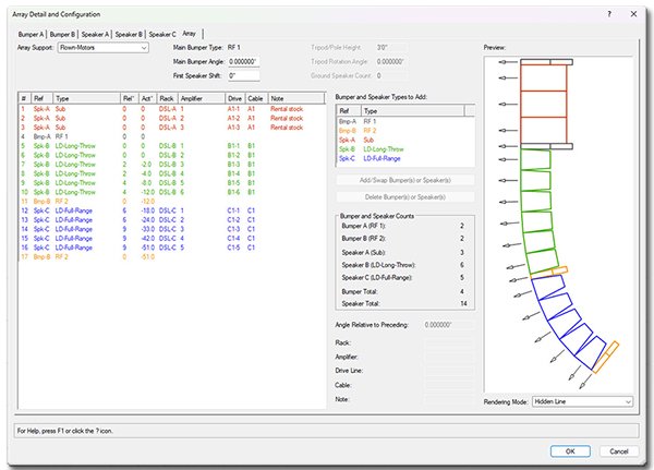
If you're interested, see http://www.landrudesign.com/VWPlugIns.htm for more info.
-
1
-
 1
1
-
-
2 minutes ago, Josh_M_Gill said:
Hello,
I was wondering if it were possible to convert pipe and drape to stanchions and vise-versa?
No.
3 minutes ago, Josh_M_Gill said:Would almost be idea if in the softgoods tool under "Function" there were a dropdown option for stanchion as well as Curtain/Border/Pipe and Drape.
When developing Stanchion Layout I toyed w. such an idea. The tools "think" differently enough that I scrapped that thinking early-on. Not a bad question, though...
-
1
-
-
3 minutes ago, Sam Jones said:
Not a big concern or rocket science, but I like to avoid the collecting global value, saving value, changing value, do operation, change value back collection of calls.
A thought: Create a Procedure called "JonesTextPlace. In it, make all of the text settings you'd like - size, alignment, justification, etc. Bookend everything w. PushAttrs & PopAttrs. Doing that will reset values automatically.
-
1
-
Landru Design Tools - June 2024 Updates!
in Entertainment
Posted
A nice way to describe the life of a developer... 😉