


MattG
-
Posts
655 -
Joined
-
Last visited
Content Type
Profiles
Forums
Events
Articles
Marionette
Store
Everything posted by MattG
-
I have a project I am working on with a grid of video. There are nine areas but they are mapping one image across all 9 things. What I am wondering is if anyone knows a way to create a solid, surface, mesh, 3d poly whatever that I can apply a texture to. This texture being the one thing I want and then just slice this one thing into the 9 pieces i need and have the texture stay the way it was supposed to. I am trying to avoid taking one image in photoshop and dicing it up there bringing it into vw 9 times and then applying 9 times. Any idea? Matt
-
I have a project I am working on where I want to have one layer render in final quality with all the other layers rendering in hidden line. The render is a viewport on a sheet layer. I prefer to do this without having multiple viewports stacked on one another, but know that is a option. My question is I know the OIP of a viewport gives you foreground and background render settings and I am hoping to be able to create this by using those. However I have no real idea how those work. Anyone have some insight they care to share?
-
Worked perfectly. My problem was that I was attempting to rotate the first box to match the angle of the curve. Thanks for the help. Matt
-
I don't use the Duplicate Along Path Tool command often. I am trying to use it for something now, but it does not appear to be working properly. What I have is a Arc and a symbol that is basically a 3'-5" x 4" box. I want to array the boxes along the arc so that they make a line without gaps that all rotate properly. What I am getting is the first few boxes appearing correct, but then none of the rest following. Wondering if there is anyone out there who has mastered this command and might be interested in enlightening me as to what I am doing wrong. Matt
-
 I am curious if anyone knows why when I use the windows hot keys for duplicate array, "Ctrl + Alt + Shift + D" my symbol insertion mode changes from standard insertion to symbol pick up mode. I use this often for duplicating a array of lighting truss and it is really annoying to constantly change the modes. I am curious if I can change a hot key combo to avoid this, but I am unsure what the hot key is to swap the mode of the symbol insertion.
 -
I am noticing that in a file I am working the fields that in the record format itself are set to numeric are showing up in symbols as numeric, but with the unit value being feet, which is not what I want. I am working on a library file and want to add symbols sizes to the record format for the symbols. My document settings are set to feet and inches. When I started I had it in inches. I was playing with how I wanted the units. I chose dimension in the record format editor for the values in question and it switched to feet. I determined that I would just use a report to change the raw units 25 into dimensions 2'1". However I cannot get it to appear as 25 anymore instead I am getting 2.08333. I am hoping someone here has experienced this and might be able to guide me on a way to correct this. My goal is to have the end result not mean that I have to go back and manually reenter all the symbols record format dimensions.
-
Pat Stanford helped me out with a project I was working on that had a similar situation. He made a video that helped. Here is a link http://www.vectortasks.com/Movies/files/Curved_Ramp.mov
-
I am working on a project where I am using referenced layers. I like this feature. However I edited a symbol in the referenced layer intentionally. Now I duplicated it and want a instance of it in the active document. I put it on a layer that is in that document, however it still says referenced. What if any is the procedure for breaking that reference. Thanks, Matt
-
The non-rotating option is not a good option because just about every light on this project is rotated on a curved truss and the spacing is too tight where that would read properly. I attached 2 images showing that. The lights have been mirrored, but in my opinion that should not matter. Whether or not that is the case is another story. What is in the images I ended up just renumbering everything just in the channel field with a prefix that is the universe. This is not what I would like to do for paperwork purposes, but graphically it looks how I want.
-
The project I am working on has label legends that have just above the light the unit number field. Just about the unit number in a row is both the universe and channel field. I have the universe field to the left and the channel field to the right. Everything is happy so far. I have a image of my label legend attached. I apply this to selected fixtures. Still happy. Now I look at a curved truss that I have the units aligned on where the fixtures are essentially rotated in the -153deg area. the unit number appears in the correct position, but the universe and channel field are flip flopping. I am also attaching a picture of this. Anyone have a solution to this?
-
I am working on a stage lighting project, but the problem I am finding is something that I am sure other people in other industries experience. The thing to do in stage lighting design is to have curved trusses with all sorts of lights on them. What I have found is the easiest way for me to be sure they are properly aligned is draw my curved truss and then draw a arc that is aligned to the pipe that I want to hang from so in my current example I have a 49'-10" Diameter Arc that is a total of a 30degree sweep. However I have lets say 6 lights evenly distributed on there. My current method is to take that 30deg and divide by 7 which I just do in the oip of the arc because it ends up being a crazy number. I then duplicate that and divide that in half and align the first one and then double the original arc and align a light to the position that the arc ends and they are all evenly distributed. I'm good right. Now the problem I want all my lights to appear to be perpendicular to the arc that I aligned them to. Does anyone have a good way to do this? Does this make sense? The lights want to rotate at a comparable angle to the arc as the arc goes along. Can anyone tell me what type of math I would need to do to determine this? Matt
-
I am not able to get what I want. I am trying to get this to wrap around the outside of a arc/circle. See my examples with what I am getting at best it is compressing on the inside. Matt
-
I am curious to know if anyone has a method of creating text that is circular. I have a few words of text that I want to wrap with the text's bottom as say a 36" diameter. Any thoughts?
-
2011 Hidden Line render in 3D text not appearing
MattG replied to MattG's topic in General Discussion
All the text that is "flat" on the ground does not render as well as the signs abouve these display walls. Matt -
2011 Hidden Line render in 3D text not appearing
MattG replied to MattG's topic in General Discussion
My issue is more in that some of the text I want to see is in the 3d portion of symbols that illustrate what they are. I do not wish to go through the various symbols reassign this text to a class and then reproduce this. Just a bug I guess. -
I am finding in a project I am working on all of my text is not appearing in a isometric, front, right or any 3d view when I apply a hidden line render. Curious to know if this is something that others are seeing or just me and if anyone can think of any obvious setting I might be missing. Examples are if I have a dimension that's plane is set to 3d and it is showing the elevation of a extrude when I look in wirframe it appears correct but the hidden line the text portion goes away while the leader lines are still rendered. I also have some text that is flat on the ground labeling a area and it is on the 3d plane, but when I go to hidden line it disappears. Matt
-
My personal opinion is that I typically work on a nice ARCH D or whatever size you want big plot and export it to a pdf that size and just prind the pdf with fit to whatever size you want to selected. I am guessing when you are trying to export to pdf you are doing it on a design layer and your page set up options are in some way goofy, that is what I would guess is your problem.
-
Not a great set but I drew some 3D connectors if anyone wants them. Matt
-
I am looking for a drawing of a multicable connector, not a flushmount, preferably in 3d. Does anyone have one they are willing to share? Thanks, Matt
-
Is this a operator error or a possible bug. I am going through some of my lighting fixture symbols and thinking it would be nice if I had all the text inside the symbols match. I decided to attempt to have all the text on the same "text style" and then if I decide to alter the appearance be it font, color, text styling or what have you I can do it semi globaly. However I am finding that when I am doing this I can select the text choose my text style from the drop down and the text takes on its attributes but the drop down reverts back to the select text style. Then if I edit the text style the supposedly assigned text does not respond. What do you guys think?
-
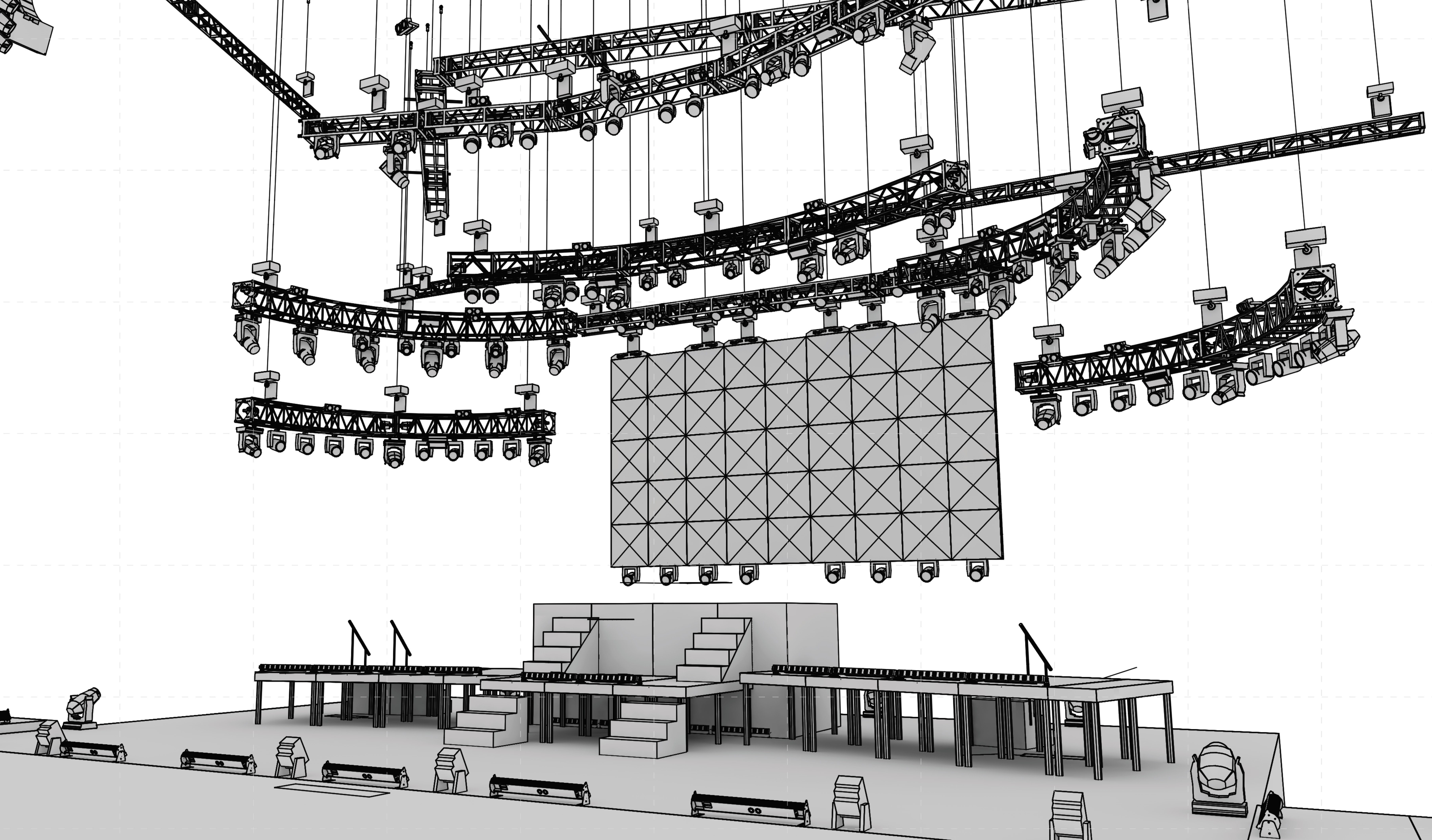
I have a project I am working on where I want one texture to map over multiple objects. I am trying to determine what the best way to do this is because I am essentially wanting it to be a "plane" type of render. My Two hopes were as follows. One was to create a bunch of 3D polys in a front view and map a texture across them. That was a no go. The other was to extrude a bunch of 2d geometry at the same time so it is all one extude, then apply the texture. Kinda works, but the prolem is that what I am trying to map is a curved video screen, so the mapping never works our correct. Anyone have any thoughts. I will try to get a samply up at some point here.
-
Cool thanks, will keep you posted giving it a try. Thanks for the help.
-
Our problem is that I have tried to choose a different location say desktop and change the name. There is no other folder or file with the same name on the desktop but it still says there is a ocnfilct. Then I cahnge the name to whatever and it still says there is a conflict. I finally choose to just replace and it does not create a folder or file with the name in that location. I try to search for the file name I just created and find it but for some reason the mac seems to think that a .dwg is a calendar item. It is really strange to me as a pc guy.
-
I am helping out a coworker with a problem he is having in vectoworks 2008 that I have never seen before. We have a file in vectorworks we go to export dwg and set the options we want and then we get a strange location that it defaults to save to and when we choose the correct location it gives us a error. I am attaching screenshots of both and not sure what is going on here. Then we go back to the screen where we choose location and we are now unable to choose the location. Anyone else ever experience similar? I am not mac savy and this is occuring on a mac, so pardon my ignorance on some of this. Thanks, Matt
-
I would do the following Go to your navigation first and be sure all your "label" classes are on. I would then be sure you have a label legend assigned to all instruments you are hoping to see this with. Be sure your labels are in the proper place on the instruments in the label legend manager. Refresh all instruments if still nothing is happening check your resource browser and in the container folder edit the symbol labeled circle or whatever container you are not seeing. Be sure the geometry shows up there and that the attributes for the line weight are what you want. After that I am out of suggestions. upload a screenshot or the file for more help. Matt