Stephan Moenninghoff
-
Posts
1,333 -
Joined
-
Last visited
Content Type
Profiles
Forums
Events
Articles
Marionette
Store
Everything posted by Stephan Moenninghoff
-

Interiorcad beginner questions
Stephan Moenninghoff replied to michaelk's topic in 3rd Party Services, Products and Events
@Daisy Y I have just finished a 11-part tutorial to get you up to speed with exactly how these things are done. It will soon appear on a screen near you. Stay tuned until mid-March for more news on this. -
Interiorcad beginner questions
Stephan Moenninghoff replied to michaelk's topic in 3rd Party Services, Products and Events
That's interesting. I don't think converting drawers into symbols is a good idea, they need to live inside the main symbol as groups/plugin objects. You can attach the file here if you like and I will have someone take a look. -
Interiorcad beginner questions
Stephan Moenninghoff replied to michaelk's topic in 3rd Party Services, Products and Events
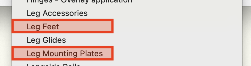
Hi Daisy, it's easily possible with interiorcad's built-in "Edit / Adapt Fitting Libraries" command. Go to interiorcad and then Fittings: From the next dialog, you choose feet and mounting plates (and, if required, accessories and / or glides). When you choose each command for the first time, interiorcad will create a new document with a sample fitting. When you save it, it will be placed in your user folder ( /Users/<your user name>/Library/Application Support/Vectorworks/2021/Libraries/Defaults/Custom Part/Leg Feet/Leg Feet - Custom.vwx) or, if you're on Windows in C:\Users\<your user name>\AppData\Roaming\Nemetschek\Vectorworks\2021\Libraries\Defaults\Custom Part\Leg Feet\Leg Feet - Custom.vwx (or Leg Mounting Plates). Edit the sample fitting geometry and replace the sample geometry with your own geometry. Add drillings if required. make sure you don't ungroup anything. Work inside the groups because there are Vectorworks Record Formats attached to the enclosing groups. If you do it like that you'll be fine. If it does not work, which is to be expected, because it never works the first time around, 😁 , upload what you tried here (the documents from your user folder) and I will have a look.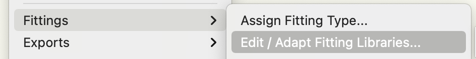

-
Cutting Sinks into Countertops and Landmark.
Stephan Moenninghoff replied to hollister design Studio's topic in Site Design
xs. -
Cutting Sinks into Countertops and Landmark.
Stephan Moenninghoff replied to hollister design Studio's topic in Site Design
Shameless plug: interiorcad does this. -
I have uploaded four new videos to our Youtube channel. I hope interiorcad users will find these useful.
-
Interiorcad beginner questions
Stephan Moenninghoff replied to michaelk's topic in 3rd Party Services, Products and Events
Only if you use the dialog (in the full version), right? I have found that using the spreadsheet it can be duplicated. Anyway, best to play it safe and not have a duplicate combination there. What I meant to say was: You can put anything in there. That column is not used for the current system any more. it is a legacy field. -
Interiorcad beginner questions
Stephan Moenninghoff replied to michaelk's topic in 3rd Party Services, Products and Events
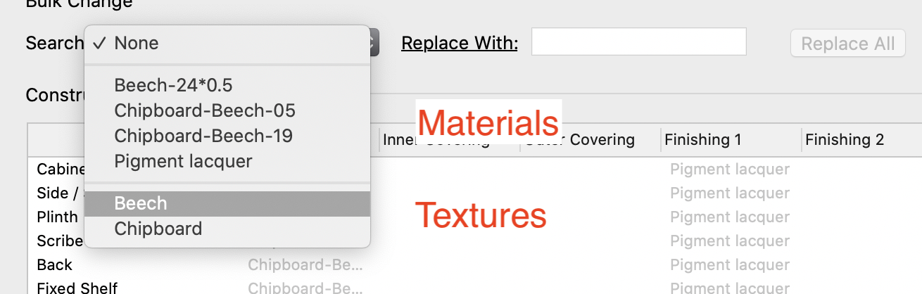
Texture is the name of the Renderworks texture. The material name is in the first columns, under #Item-No. Thickness is also important because it will govern the physical thickness of each material in the model. You can ignore Group. -
Interiorcad beginner questions
Stephan Moenninghoff replied to michaelk's topic in 3rd Party Services, Products and Events
We use these classes to create the grid surfaces between custom parts when we place fittings. Obviously, with most fittings, they go *between* two custom parts, so if we kept the custom parts visible, you wouldn't be able to place the fittings. These classes create the blue grids and at the same time grey out the parts proper. Users have got quite creative in the past with these classes, renaming them, making them visible, giving them different attributes etc. This could break the function, so we are creating these classes from scratch every time a new document is opened. Grids.mp4 -
Interiorcad classes
Stephan Moenninghoff replied to michaelk's topic in 3rd Party Services, Products and Events
No 🙂 -
Interiorcad beginner questions
Stephan Moenninghoff replied to michaelk's topic in 3rd Party Services, Products and Events
Those are some special classes which I think we reset hard after some operations. I think this is new. -
Is this the forum link?
Stephan Moenninghoff replied to jgmrussell's topic in 3rd Party Services, Products and Events
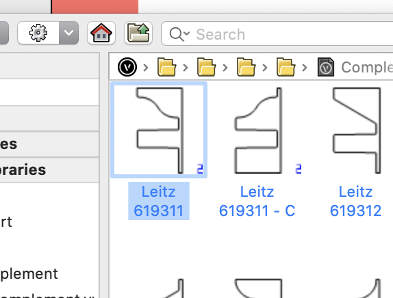
Great example and -finally- fully supported by interiorcad 2021. I have set a frame up for you with a standard pre-supplied profile. You can find the profile now in your document under interiorcad > profiles. It is not a plain profile yet. You need to edit the 2D component of the profile and change the polyline to become square instead of profiled, whilst keeping the dado. You need to edit both the profile and the counter profile (the one with the - C suffix). You NEVER use the counter profile. It is used by interiorcad automatically when you set the joint for stile and rail to "counter profile". You can add the profile to your user folder. We will soon add it to the dialog under interiorcad > Fittings > Edit / Adapt Fittings Library but it already works if you go through the Finder / Explorer. Let me know if this works for you!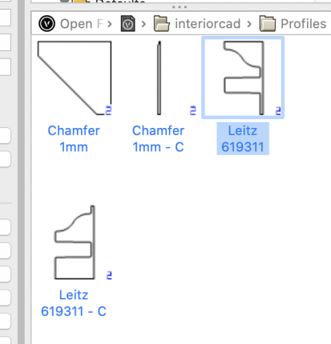
-
Is this the forum link?
Stephan Moenninghoff replied to jgmrussell's topic in 3rd Party Services, Products and Events
Can You send me your profiles? I will have a look if you want. -
Is this the forum link?
Stephan Moenninghoff replied to jgmrussell's topic in 3rd Party Services, Products and Events
What's your question? -
Need help Exporting from VWX to DWG
Stephan Moenninghoff replied to s1mu's topic in General Discussion
That's the issue here. CNC equipment expects only arcs and corner vertices. This is the same across the board, from the smallest model-building CNC to large nesting CNCs in the furniture industry. interiorcad automatically converts beziers to arcs when a custom part is created from a curve. If you want higher fidelity, your best strategy is to draw the primitive again, using only arcs and corner vertices. -
Interiorcad beginner questions
Stephan Moenninghoff replied to michaelk's topic in 3rd Party Services, Products and Events
In case you haven't had a good look at the interiorcad Custom Part - here's a little inspiration: -
Interiorcad beginner questions
Stephan Moenninghoff replied to michaelk's topic in 3rd Party Services, Products and Events
Excellent summary of board types, @mgebel. To add to that:- there are seven board types with only three different patterns. Solid type Solid Wood Glass Plywood Laminated Wood Composite type Melamin Faced Veneered Standard 1. The first group can not receive edge banding or any covering at all but has variable thickness. This means you can adjust the thickness of these materials in the OIP. 2. The second group receives edge banding but not coverings. You should not set the thickness of the coverings to 0 in the Master Data setup because it will not render well. Any thickness you assign to a covering will not be added on to the material (as @mgebel already pointed out) so, give it at least 0.1 of a mm. 3. Standard Materials like chipboard or mdf expect to be either edge-banded or coated or covered/veneered. All coverings will add their assigned thickness to the total thickness of the finished material. So, if you have an 18mm board and you add on 0.5mm on both sides, you end up with 19mm finished thickness. @Habitat43 you do not need to go to such lenghts if you want to simply explode a cabinet object. Just ungroup the cabinet. The first ungroup will decompose the cabinet into custom parts. All custom parts are still intact and can be assigned a material, edge banding, fittings etc. They cannot be reshaped as a cabinet any more, that's all. This is a great way to overcome any limitations of the cabinet object without destroying cutting list or cnc information. If you want to go further, first make sue that "3D Details" is disabled for the cabinet in the OIP before you ungroup the top level cabinet (because that will get rid of all physical representations of coverings and edge bandings.). Then, ungroup and then, ungroup again. You end up with generic solids that can be easily textured (but have no meta-information any more) A more recommended workflow is to use the Search and Replace command in the cabinet dialog which you can apply to just textures, ignoring the material data .The Search dialog will automatically list all materials and textures that are being used for the edited cabinet.There is also a standalone command unter the interiorcad menu to search and replace all cabinets in the document. That's even faster than decomposing and manually assigning the textures.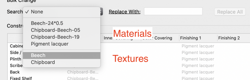
-
Interiorcad beginner questions
Stephan Moenninghoff replied to michaelk's topic in 3rd Party Services, Products and Events
It never expires but you may find it tedious to keep working around the one-cabinet limit eventually :-). -
Interiorcad beginner questions
Stephan Moenninghoff replied to michaelk's topic in 3rd Party Services, Products and Events
Textures and materials are one entity in interiorcad. Each material has a texture and a thickness assigned to it as well as a 'material type' So, we discriminate between melamin faced, solid wood, raw, etc. In order to change a texture, you must define the texture for the material used for construction. This is necessary to ensure that cutting lists are always up-to-date and no material can be assigned that is either anonymous or has the wrong constructive thickness. Go to interiorcad -> Master Data -> Boards and define your materials there. Likewise for edge banding and coverings/veneers. On a second note we do realise that we are thinking too much like a joiner/cabinet maker rather than a designer and we think a future version might support double-clicking a texture in the Resource Manager and just pouring that texture over the entire cabinet, even before a proper material gets assigned. This is very much an experimental idea tough and not guaranteed to be implemented. -
Interiorcad beginner questions
Stephan Moenninghoff replied to michaelk's topic in 3rd Party Services, Products and Events
BTW check out my Marionette "Kitchen Shelf". It will make it a lot easier to place and distribute items in your cabinets. -
Interiorcad beginner questions
Stephan Moenninghoff replied to michaelk's topic in 3rd Party Services, Products and Events
Of course. Let me have your social media links please! That is fine but maybe you are not using the EAP to its full potential in this case? You can convert the path to a NURBS before you start and then place a working plane at the end. You can actually click on the end point of a NURBS curve with the WP tool and the WP will be placed perpendicular to the path. Then, you draw your profile on the WP and when you perform the extrusion, you check "Fix Profile".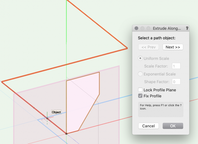
-
Interiorcad beginner questions
Stephan Moenninghoff replied to michaelk's topic in 3rd Party Services, Products and Events
Lovely stuff. Would it be objectionable if I put this up on our render gallery? Could you contact Sven Biermann please for subscritions? His email is sven.biermann@extragroup.de. Thanks and keep it coming! -
Is this the forum link?
Stephan Moenninghoff replied to jgmrussell's topic in 3rd Party Services, Products and Events
Yes, it is. Thanks for your questions! The extra length for the rail? It is added automaticall by choosing a profiled connection: The profiles with the '- C' appended should not actually show up, please don't use those. They get assigned automatically. This is where the length gets added (unless you mean some length on top of that for sizing the parts. That is not possible yet but a longstanding wish, also for mitered boards) It will automatically be included as long as it has been assigned a material. Go to interiorcad -> export -> cutting list. This will create a csv file with all parts included. We have planned to add finished sides as a new part type for the cabinet for later this year / early next year.
-
Interiorcad beginner questions
Stephan Moenninghoff replied to michaelk's topic in 3rd Party Services, Products and Events
Hi Michael, you are certainly diving in at the deep end. 🙂 1. the door on the side of the upper cabinet over the sink -> Draw a cabinet with that type of door and hide all the parts you don't need (that is everything except the door and face frame) . You can do that by switching those parts off inside the configuration dialog. Hide the side panel of the cabinet. Replace with the door. 2. the corner legs on the cooktop cabinet -> That's a modelling challenge rather than an interiorcad question. Easy boolean operation between two extrudes. 3. the double pulls on the drawers -> Ah, good point, we need to add the second handle back for drawers. You can either place one handle with an offset. This will import that handle into your document. Then, with the symbol insertion tool, add the second handle. It will even connect with the drawer front and add the drillings. Or, create a double handle as a single symbol. 4. the hood enclosure. Not even sure how to start that one :-). -> you could use single framed fronts (with hidden cabinet parts) as well or model from scratch. Obviously, those X-es need to be added in manually. You could also use a Marionette object and add that to the cabinet. (Yes, interiorcad supports adding Marionettes to all of its boxes!) 5. the glass doors with muntins. -> Sorry, no muntins yet but on the near-term radar. You can either add them via Marionette or model them otherwise. 6. the arched toe on the sink cabinet. -> You can either Delete the plinth, add an extra box and create a framed front, hide the stiles and bottom rail and set the top rail to 'arched' Use an interiorcad contour to create the routing in the plinth. That is much quicker but not as parametric. If you resize the cabinet, you need to adjust the routing. Let us see what you created when you've finished! HTH -
You can do that already, except the UI sucks. We are going to introduce a new way of doing this. And this time, it will be for both vertical and horizontal partitions, not just vertical.