
Michael Siggers
-
Posts
125 -
Joined
-
Last visited
Content Type
Profiles
Forums
Events
Articles
Marionette
Store
Everything posted by Michael Siggers
-
 Hi @line-weight I think I understand that, although maybe that's a can of worms I'll open when I get a little more proficient. Don't suppose yiu have a visual example of a merged section? On a side note, it's amazing how it takes so long to unlearn keyboard shortcuts from previous software. Must be some sort of muscle memory. The amount of time I keep pressing Space for the Selection tool is ridiculous 🙂 Mike
 -
Thank you @Tom W. Yes, must admit, I don't use 3D sections much in my work, it's just that as I'm in the process of transitioning to Vectorworks, I'm trying to recreate things that I have done, I do, or may do, or may need, if that makes sense. Mike
-
Thank you @Kevin K and @Tom W. Not sure where I would be without this Forum. Extremely helpful. I will give that a go. As mentioned, I think I'm on a steep learning curve and feel like I'm playing catchup. Still, enjoyable learning though. Mike
-
Thank you @Tom W. So, just to confirm, this is a little bug which is being worked on? Mike
-
Hi @Kevin K Apologies for jumping into this thread, but this is exactly what I am looking for. So, please bear with me as I'm in the process of transitioning to Vectorworks from my current software, so am on a (steep) learning curve at the moment. Anyway, would you mind explaining about creating the Class used to grey background items out and how this works if Items are already assigned to Classes, such as 'Windows', 'Doors', etc. Is it just a Class which is ONLY assigned/applied to objects beyond the cut plane when specified in that dialogue box, for that specific Viewport, ie. it doesn't change the actual Class of the various objects? Kind of a temporary Class only used in that situation? Kind regards Mike
-
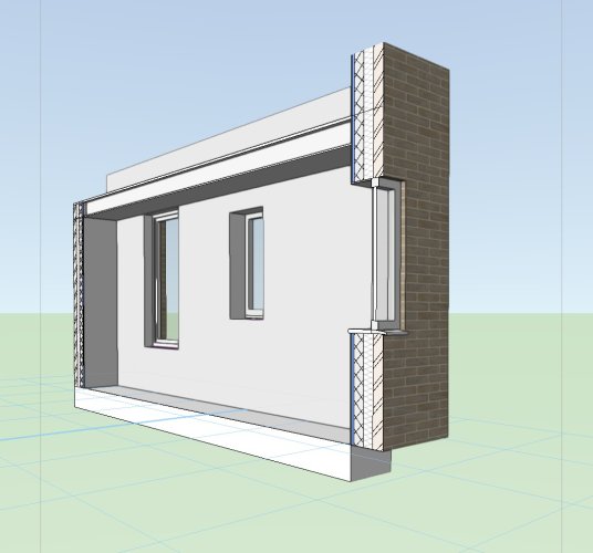
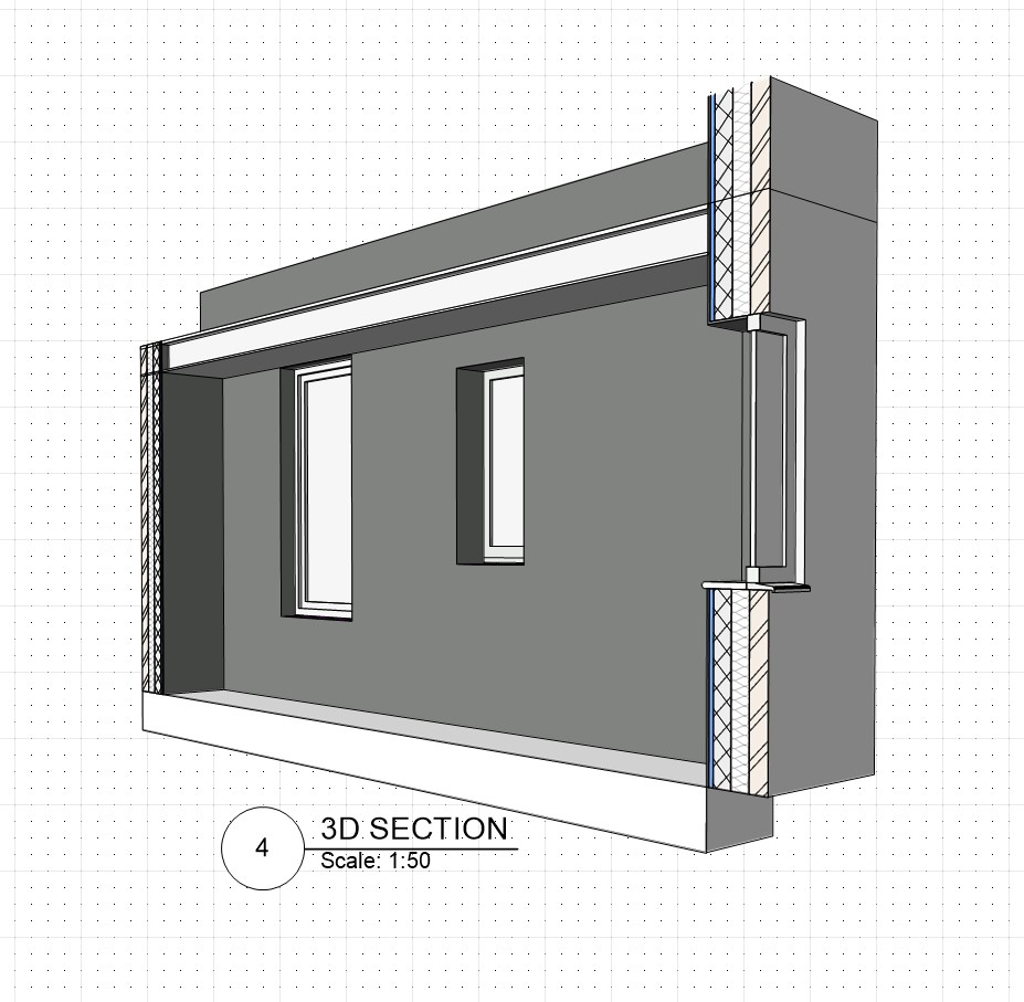
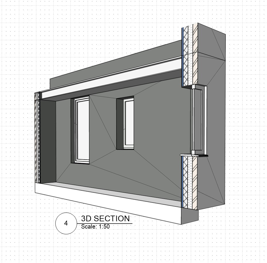
Hi I am really struggling to create 3D Sections. When I do, I think is more by luck than anything else. I can not believe the process is so convoluted. Anyway, down to the queries. I have attached a file which is one of the ones I have been using to try and learn Vectorworks and using Window Symbols that I have created to make sure they insert correctly, (Still some work to do on those, but so far so good). Also been trying to get to grips with Levels and Stories in it. However, in this File example, for the life of me, I can not seem to get the textures to appear on the surfaces in the 3D sections, even though they clearly have a Texture applied as part of the Wall Class and can be seen in the Elevations. Would greatly appreciated any thoughts, input and advice. I thought it might be to do with Classes etc, but I'm really struggling to find a solution. Also attached are some screen shot of the 3D sections rendered in both Shaded and Renderworks Fast. As can be seen from the Shaded version, there are lines breaking the flat surfaces. The only way I can get rid of these is to select do not show edges from the advanced options for the Viewport. If I select a Renderworks Shading they disappear. At first, I thought is might be a result of the Window Symbols that I had created, but I opened another file which had just Vectorworks windows in, and the same lines are shown. Again any thoughts on this would be helpful And finally, are there any detailed, step by step instructions for creating 3D sectional Viewports using Version 2023, because all the ones I have found are in previous versions and do not seem to match version 2023. Any thoughts on how I have set up the 3D Sections, in terms of their Layers. I created both using the Clip Cube and placed them on separate Layers. Is this correct/good practice when creating multiple 3D Sections. Should they be placed in a Class? Just can not seem to find any guidance on this. And finally, finally........ I am hoping this is just a steep learning curve but I've been trying to solve the above for about 5 hours. Someone please tell me it gets easier 🙂 Kind regards Mike 1998672728_Practice4-WindowSymbolsInsertion.vwx

-
Symbols and Move by Points - Reference point seems to jump
Michael Siggers replied to Michael Siggers's topic in Architecture
Thank you @Tom W. Very much appreciated. As you can probably gather, I'm still in the process of getting to grips with Vectorworks before I transition from using Sketchup Pro. Mike -
Symbols and Move by Points - Reference point seems to jump
Michael Siggers replied to Michael Siggers's topic in Architecture
Hi @Tom W. Ah, yes, I figured this bit out after the original post so I now have a window which cuts a hole omitting the sill drip edge. So, that's better. Still confused with the move by points though. If I click on a reference point and then move by say 200, the window jumps up the original 900 plus the 200, so effectively moving up by 1100. It's the reference point I select, it's as if it is located at the base of the wall, even though I click on an actual window point. If I use Move by Points on any other item, such as a plan rectangle, the reference point stays where I click it. Mike -
Hi I seem to be having a problem with using the Move by Points tool after inserting Symbols that I have created. To help explain, two files are attached, the one with the Windows that are being created as Symbols. I have so far converted two of them to Symbols. The other file is where I am experimenting with inserting these windows into a wall to make sure they look ok and work as expected/intended The problem/query is as follows. When I insert the window, it is inserted at ground level. This is ok, as I then move it to the correct height using the Move by Points tool. All good so far. However....... if I then try to use the tool to move the same window up or down again, when I click on a reference point on the window frame, the new position for the window is effectively shown offset by the amount I moved it before. It is as if the reference point for the move is still using the bottom of the wall. I'm thinking it's something to do with how I have created the Symbols, and that I have missed something, but I can not think what. Any thoughts would be greatly appreciated. Kind regards Mike Standard Windows.vwx 842459462_Practice4-WindowSymbolsInsertion.vwx
-
Think I have managed it. Found the Option to Modify Camera View for the Viewport. Mike
-
Hi Would you happen to have a step by step on this, as I really can not get it to work. Mike
-
Hi Really struggling with this. Any chance of some step by step instructions? When I change the Viewport to Perspective, the view reduces to a 1cm square, and when I try to change the crop, it will not let me. At this moment, I'm thinking it will be easier to produce the calculations required to land a rocket on the sun. Mike
-
Brick Banding and Window Head and Sill Detail
Michael Siggers replied to Michael Siggers's topic in Architecture
Yes, thankyou for this. I have been using that quite extensively and found it very helpful, but not got round to the creating Symbols detailed instructions. Mike -
Brick Banding and Window Head and Sill Detail
Michael Siggers replied to Michael Siggers's topic in Architecture
One final question for today......... I promise 😉 If I create my own Windows as Symobols, which should be ok to do, (in theory) as I have an extensive library already created in Sketchup Pro, these can be inserted into walls in the same way, with the wall creating the internal wrapping etc? It reminds me of the days when I first learnt AutoCAD, before time began. It was quite un-intuitive, but as time went by, it became easier and you realised how powerful it was. Mike -
Brick Banding and Window Head and Sill Detail
Michael Siggers replied to Michael Siggers's topic in Architecture
I did wonder about that as a possibility. I may try that when their is only Brick banding. Mike -
Brick Banding and Window Head and Sill Detail
Michael Siggers replied to Michael Siggers's topic in Architecture
Brilliant! Thank you @line-weight That is what I was thinking and sounds like the perfect approach. Useful to know about windowless openings as you've pre-empted the next thing I need to look at 😉 Mike -
Brick Banding and Window Head and Sill Detail
Michael Siggers replied to Michael Siggers's topic in Architecture
Found it after much digging around 😉 Now wrapping on all 4 sides. Mike -
Brick Banding and Window Head and Sill Detail
Michael Siggers replied to Michael Siggers's topic in Architecture
Thank you everyone Calling it a day on Vectorworks for today. Need to get on with some work. I started getting bogged down in why I can only get the Internal Finish to wrap into the opening on one side, and not the head, sill or left side, (as looking from the inside), unlike the example which @Christiaansent me which wraps into the opening on all sides. Given up for the day as I need to be working. Mike -
Brick Banding and Window Head and Sill Detail
Michael Siggers replied to Michael Siggers's topic in Architecture
That's great. Thank you so much. I feel like I'm getting there..... slowly but surely. Mike -
Brick Banding and Window Head and Sill Detail
Michael Siggers replied to Michael Siggers's topic in Architecture
Thankyou @Christiaan That worked for the Glazed and it is now showing. Mike -
Brick Banding and Window Head and Sill Detail
Michael Siggers replied to Michael Siggers's topic in Architecture
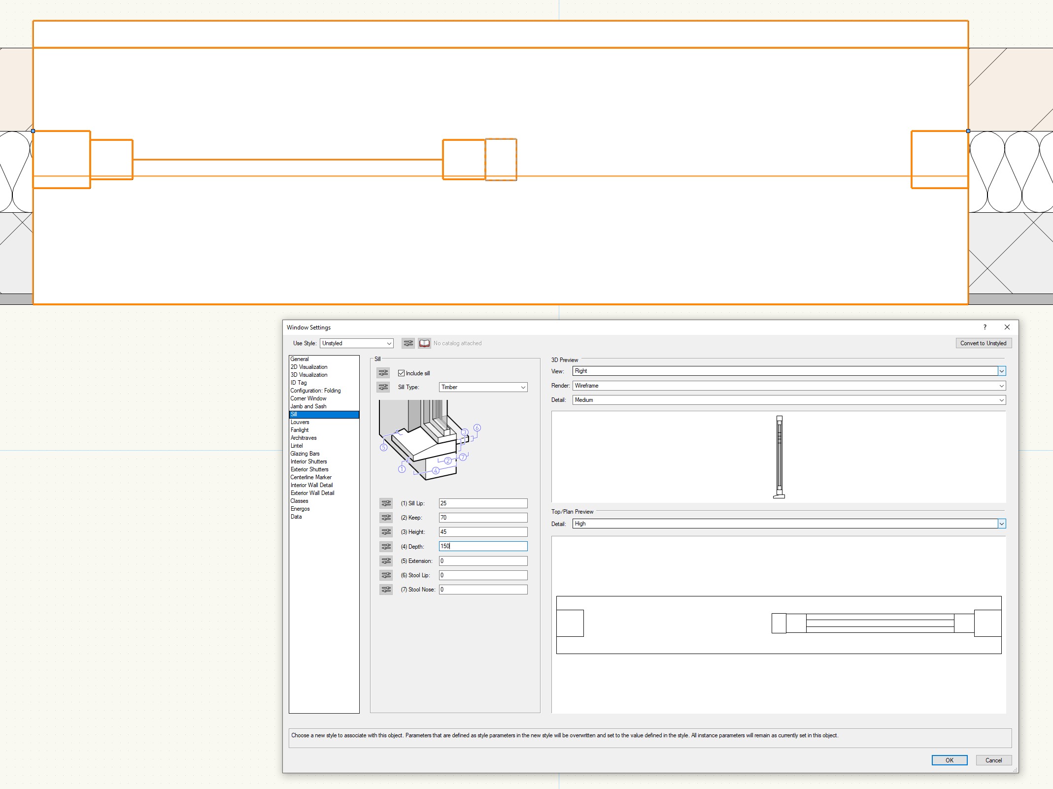
Just before I crack on with some work....... Attached is a screen shot, showing the Window Settings. I can not for the life of me get the Window Sill to line with the back edge of the Window Frame. Think of a Standard uPVC Window. Even though the 3D illustration shows the Sill as aligning with the Window Frame. Is this because the Window Tool is set up for non UK windows I wonder? This also shows the missing glass in the Layout as well as in the Preview in the Window Tool. Mike
-
Brick Banding and Window Head and Sill Detail
Michael Siggers replied to Michael Siggers's topic in Architecture
Hi @Christiaan File Attached This is work in progress practice work based on a project already completed for a Client. Thought I would try and recreate it in Vectorworks to learn. Mike 1132810628_7TheSycamores.vwx -
Brick Banding and Window Head and Sill Detail
Michael Siggers replied to Michael Siggers's topic in Architecture
Thank you @Christiaan One of the Issues with the Window Tool is the Sill. It seems to place it incorrectly and lines it up with the internal face of the wall, and not the internal face of the window frame. The Windows shown in the previous attachment were created using the Window Tool, but it seems to miss glass off and I can not seem to change the Glazing to Double Glazed. I do already have a library of 3D windows that I have created over time in Sketchup Pro, based mainly on Jeld Wen Windows, which covers most of the Window Styles I use. Any bespoke windows can be created as required. Mike -
Brick Banding and Window Head and Sill Detail
Michael Siggers replied to Michael Siggers's topic in Architecture
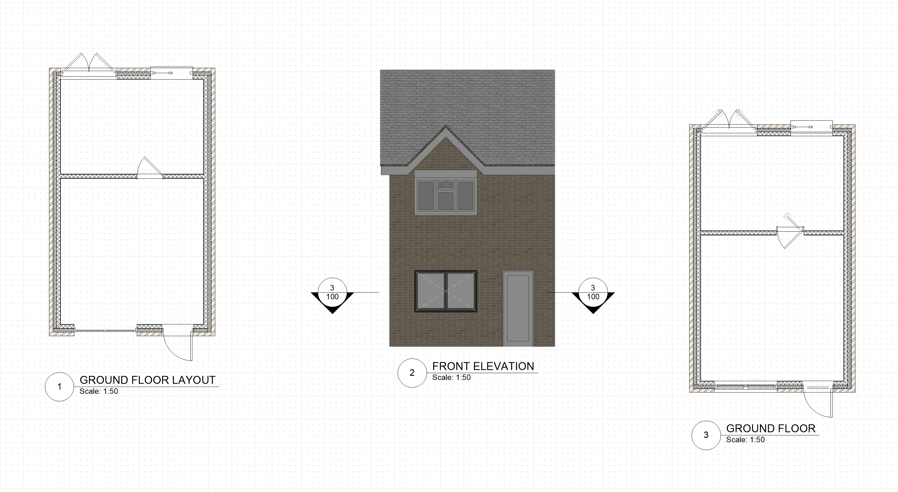
Many thanks for the answers. Very much appreciated. Looks great on the examples provided, so that is what I will do. ............ Once I can sort out the Windows and Doors. Having serious issues with them, as shown in the attached. The Layout on the Left is just the Plan View from the Model. I noticed the Missing Glass in the window. I tried changing Detail level to high but was still missing. The Top Window next to the External Double doors is a Vectorworks window modified to be 1200 x 1200 with a Top Light on the right side as looking externally. The Glass in the Right side is a Fixed Leaf. The window on the bottom, next to the Single External Door is a Windoor Window, but there seems to be no options to make it a standard Casement window with a top opening light on one side, similar to what is shown on the Front Elevation, but a 2 light window rather than 3 Light. The Front Elevation is shown in the middle. This shows the Windoor Window, which I can not make look like the window on the First Floor. The Plan Section on the right was created by Creating a Section from the Front Elevation. I wanted to see if the windows showed correctly. This has infact made it worse. The window at the top has moved outwards. The Front Entrance Door at the bottom shows some double lines, presumably the panel. As for the Internal Door, no idea what is going on here. The internal door in the left Plan is incorrect anyway, as I can not seem to get it to line up with the wall finish correctly. So, struggling really and not sure what to do. I really want to get on with this Software, but at the moment I feel like I am fighting a losing battle. For the windows, I am wondering whether I need to go down the route of modelling my own windows and create Symbols for a Standard Set, adding to this over time. Could be a pain as a lot of properties I survey are Victorian, so not exactly Standard Windows. Any thoughts and suggestion would be most welcome. Mike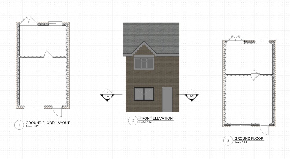
-
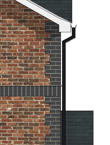
Hi I'm looking for some advice on creating a particular detail using Vectorworks Architect, concerning Brick Bands, Window Head and Sill, and Corner details. A little bit of background first. I am a freelance Architectural Technician and have been using Sketchup Pro for what seems like since the year dot. I undertake work for both the Commercial and Domestic sectors. The domestic sector is concerned mainly with new Extensions and remodelling of Properties. Both the Commercial and Domestic sides involve Planning Submissions and Building Control approval. I have finally taken the dive and decided to use Vectorworks Architectural for my work, as it seems to offer a lot more than Sketchup Pro, is more powerful, and still talks with Lumion, which I use for Renderings. The idea is to use it in parallel with Sketchup Pro so that I can get up to speed before I stop using Sketchup. As such, I have started by trying to recreate a Project I have completed in Sketchup to familiarise myself with the software. So, here is the query. I have attached a couple of images from this project which shows extracts from the elevations created in Sketchup Pro, which feature brick banding and Head and Sill Soldier brick courses. For all of my research, Googling, watching many Youtube videos, Vectorworks Tutorials etc., I can not seem to find a way to achieve this in Vectorworks. In Sketchup, the outer leaf of the wall was created as a Component and then edited to add the lines on to separate the surfaces, which could then have a separate texture applied to the areas as required. I am figuring that I can not achieve this with the Wall Tool. (The wall tool is great and will save me time when producing the drawings for Building Control). I thought maybe I could just create the outer leaf as a solid, similar to Sketchup, but I can not find a way to divide the surface and apply different textures to the areas that require them. Anyway, any help, thoughts, and advice would be greatly appreciated. Mike