
Michael Siggers
-
Posts
123 -
Joined
-
Last visited
Content Type
Profiles
Forums
Events
Articles
Marionette
Store
Everything posted by Michael Siggers
-

Red Rectangle in Design Layer View
Michael Siggers replied to Michael Siggers's topic in General Discussion
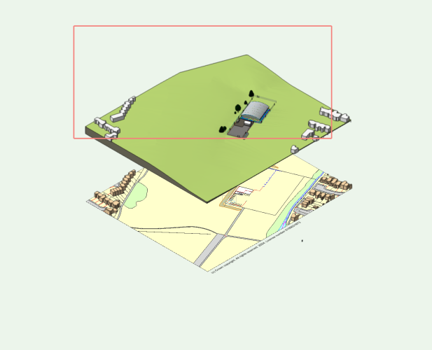
So, found the cause. The Terrain needed updating even though I had made no changes to it, although I did relocate the whole model to the Origin as it was causing problems with the display, showing loads of lines all over the surfaces. I'm therefore assuming the terrain required updating because of this. Mike -
Hi Would anyone be able to shed any light on why there is a red rectangle in my Design Layer Viewport, shown in the attached screenshot. All references are up to date. Kind regards Mike
-
This looks very interesting and will definitely look into this and the one @Tom W. is showing, as I have this situation quite a bit. Mike
-
Thank you @Tom W. It would be helpful if the points you have made were mentioned in the videos which Vectorworks post. Really appreciate you looking at the model and explaining your solution. Will definitely be incorporating that in the future. For this one, I think I will use 3D solids as there are some more wall 'add-ons'. As this is the existing property and the proposed works will not change this, I think in this case using solids should be ok. I will need to perform an 'Extract Surface' above this as the top portion is rendered. Again, this will not be changing for the proposed. Kind regards Mike
-
Hi I have watched the video regarding creating wall projections and wall recesses. Very good an informative......... although maybe missing some more information. So. all good I thought. Attached is a model I am currently working on and it has a brick feature that wraps around the entire house. I modelled the feature, (a simple brick banding). In the attached model, this is still an extrusion ready for creating the wall projection feature. I then selected all the walls to which it applies, and the feature band, and applied the Wall Projection from the AEC Menu. Well. it does not seem to like wrapping around multiple walls/ corners. I tried the following; Placed a feature band on only one of the walls running the full width of the wall. When I used the AEC/Create Wall projection, it messed it up, moving the start to the centre of the perpendicular wall and over shooting the other end. No changing any of the option for the feature band made any difference. In fact in the list of where to place the feature band, which gave me a few options, the only one it would accept is 'Centre of the Wall', the default one. The Plan view looked even worse as it looked like there was another complete wall sticking out of one end. I then created a single wall on its own, and created another feature band running the full width of the wall. This worked better, although it did move the feature band very slightly, which could be seen when zoomed in on the Plan view. The theory is that I can not apply feature bands the full width of a wall when the wall is joined to other walls with corners. And, it also does not really like applying wall features the full width of a wall. It seems my only option is to leave it as an extrude, add it to the relevant class and call it a day. To conclude, maybe the video which was posted should be expanded to show how to add wall features around corners. Would also be good to explain the options in the OIP once the feature is created. Would be greatly appreciated if anyone could look at the attached a confirm that my conclusion is correct. Just don't fancy wasting my time trying to make something work if it does in fact not work. I can then at least carry on with the rest of the model. Kind regards Mike https://www.dropbox.com/scl/fi/bbjxufhq1dyezltz58mt3/C02-2024-01-257-Penrith-Road-Planning.vwx?rlkey=co21xf6zqhxvlnyta0alu6ag2&dl=0
-
Sending to Site Surface - Confirmation
Michael Siggers replied to Michael Siggers's topic in General Discussion
This is what I did. I had to find it first, but then used move by points and then elevation, (Z Height). MIke -
Sending to Site Surface - Confirmation
Michael Siggers replied to Michael Siggers's topic in General Discussion
Hi @Tamsin Slatter Unfortunately when the Building was created, the Client had not chosen a location. I did think it would be good to have an option of where to place the file, when using a Design Layer Viewport, similar to the option when creating a 3D Symbol. ALong the lines of "Insertion Point: next Mouse Click?", if not wanting to use the Georeferenced location. Mike -
Sending to Site Surface - Confirmation
Michael Siggers replied to Michael Siggers's topic in General Discussion
@Tom W. Also, wanted to say a massive thankyou for your help over the last few days. Been absolutely brilliant. I'm persisting with Vectorworks as I think the more I use it the easier it will become, (hopefully 🙂 ). Just damn difficult, and frustrating, at times, especially when working on live projects. Not the most user friendly software. Reminds me of learning AutoCAD many centuries ago 🙂 Mike -
Sending to Site Surface - Confirmation
Michael Siggers replied to Michael Siggers's topic in General Discussion
Thank you @Tom W. Yeah, the Model of the Building is not Georeferenced so that makes sense. In this case, the model of the Facility was created before the location was confirmed by the Client. Would be nice if there was an option to physically place the Design Layer Viewport though, once created, to save trying to find it in the Model. Maybe an "Insertion Point: Next Mouse Click?' option similar to when creating a 3D Symbol. Mike -
Create Mesh Fencing - Any Help would be appreciated.
Michael Siggers replied to Michael Siggers's topic in General Discussion
Although I have just done this in the Object Style in Resource Manager. Would it not be simpler to just be able to use the OIP to assign the Class? Seems a bit convoluted having to assign the class in the Object Style through Resource Manager. MIke -
Create Mesh Fencing - Any Help would be appreciated.
Michael Siggers replied to Michael Siggers's topic in General Discussion
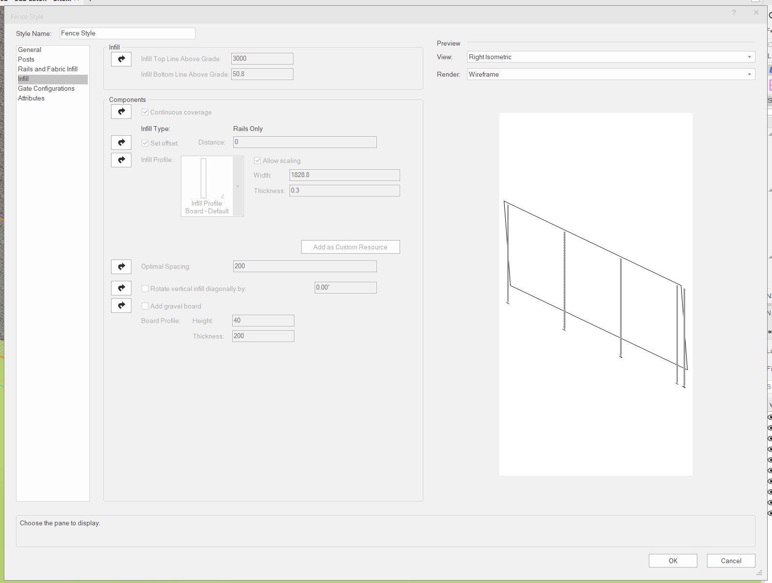
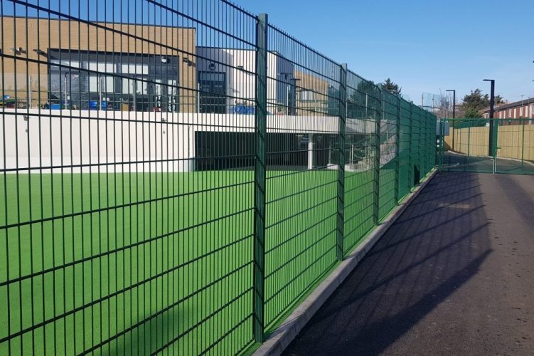
Hi @Tamsin Slatter Yes, I did watch the videos. Attached a a screenshot of the fence I created, by choosing a similar Style, Making Unstyled and then creating a new Style. Seemed to work ok. Have not tried inserting any gates in yet, but will probably do those manually as one of them is a Sliding Gate. One thing I could not do is assign a Class to the Fence in the OIP, as this was greyed out. Mike -
Screen Plane - Seems to enable after drawing a Fence
Michael Siggers replied to Michael Siggers's topic in General Discussion
Yes, I did check that dialogue box and the option is unticked. Mike -
Sending to Site Surface - Confirmation
Michael Siggers replied to Michael Siggers's topic in General Discussion
Hi Tamsin The Site Model is the active file. The reference is the building I created which sits on the Site Model. I have referenced the building so that when I update the building, the Site File, (used for Planning), will update automatically. Also, when I inserted the building using a Viewport on a Design Layer for the Building, it placed the Building miles away from the Site Model. This is because the Site Model is Geolocated, but how do I control where the referenced file appears when I do reference a file? I had to find the Building and then move it to where I needed it. Mike -
Hi A quick one this evening. Just want to confirm that it is not possible to use Send to Surface on an Imported/Referenced Model. Tried it but it did not work and trying to use it on a Referenced Model is not mentioned in the Vectorworks list of items which can be sent to surface. I have changed the 'Z' height to sit it on the Planar Pad. Kind regards Mike
-
Ho do I stopp Screen Plane from kickjing in after drawing a fence? Mike
-
Create Mesh Fencing - Any Help would be appreciated.
Michael Siggers replied to Michael Siggers's topic in General Discussion
Why is the dialogue box in the attached greyed out? Mike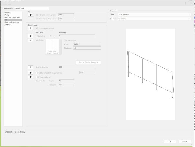
-
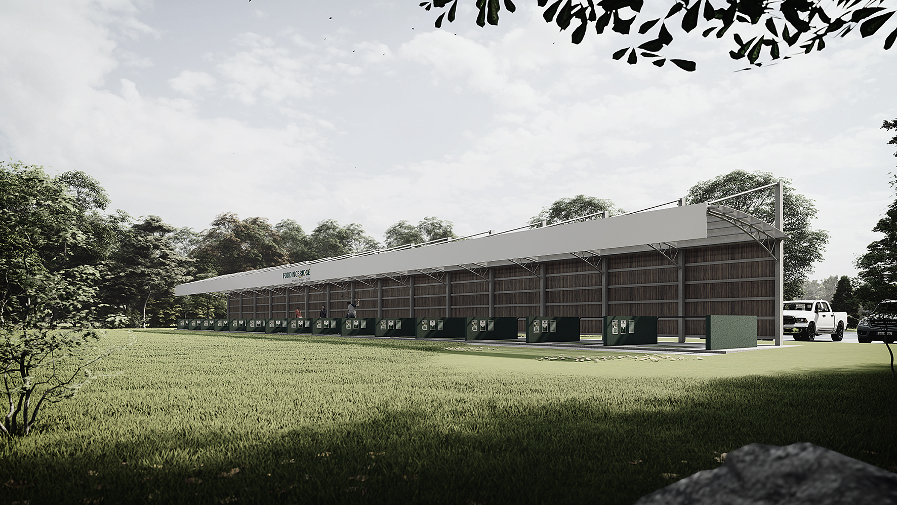
Hi Rather than continuing to waste my time trying to use the new fangled Fence tool, (wasted over an hour so far), can anyone help in creating the attached fence style please. Mike

-
Can you issue a full set of instructions please. Trying to create a Mesh Fence, and the option it states I need to select for a Mesh fence, called 'Soft in the Infill Style under the General Tab, DOES NOT EXIST. Wasted over an hour so far trying to create a Mesh Fence, like the attached. Mike
-
But do they actually then try to use it, in the real world?
-
Hi Anyone with full instructions on using the Fence tool in Vectorworks? Wasted an hour so far trying to created a Mesh Fence. Getting sick and tired of Vectorworks. Mike
-
Hi So any instruction on how to use this? Trying to create a Mesh fence and the dialogue for 'Infills' is greyed out. Also, under 'General' Tab, 'Infill Type', according to the help section at the bottom there should be an option for 'Soft', which it states is used for Chainlink, Mesh, and similar. NO OPTION EXISTS. Vectorworks is extremely frustrating and I'm sure whoever writes this imagines the most complicated way of doing it without any instructions. Would have taken me 2 minutes in Sketchup, but here I am 1 hour later in Vectorworks. PLEASE POST SOME DETAILED INSTRUCTIONS. Mike
-
What about Classes? What Class should I put them on? Mike
-
I'm really struggling with this. What about classes? None of the Videos explain it very well. I currently have a Site Model and a Planar Pad Modifier which is having no effect on the Site Model. I have attached the model as I am really losing the will to live. What am I doing wrong? https://www.dropbox.com/scl/fi/zq1xi9k2xe60vrcl3wpjy/C11-2023-02-ECB-Luton-Site-Layout-Planning.vwx?rlkey=pvvw17hvpdthtxyfez5iwbiuq&dl=0 Mike
-
@Tom W. Hi Tom Still, persisting with this. Watching loads of Vectorworks Videos etc. Simple Question: What layer am I supposed to be on when I create Site Modifiers? Trying the create a Property Line. Video shows this being done in 2 minutes. 30 Minutes later and I ma still trying. None of the videos cover this simple question. Mike
-
Thank you @Tom W. Was just in the process of reading about that 🙂 Mike