


Pat Stanford
-
Posts
12,649 -
Joined
-
Last visited
Content Type
Profiles
Forums
Events
Articles
Marionette
Store
Posts posted by Pat Stanford
-
-
Type it in where you show the highlight?
I think if there is only one viewport and you click the update scale button it will use the viewport scale.
-
 2
2
-
-
With the object(s) selected, change the class in the OIP and you can set it to whatever class you want.
Or goto Tools:Plugins:Plugin Manager and create a new Command. Copy and paste the following script in to the command script. Then edit your workspace to add it to a menu and give it a keyboard shortcut. This will change the class of all visible selected objects to the active class.
Procedure ClassAsActive; {December 10, 2019} {©2019 Patrick Stanford pat@coviana.com} {Licensed under the GNU Lesser General Public License} {Sets all visible selected object to the active class} {No warranty expressed or implied. Use at your own risk} Procedure Execute(H1:Handle); Begin SetClass(H1,ActiveClass); SetSelect(H1); ResetObject(H1); End; Begin ForEachObject(Execute,((VSEL=TRUE))); RedrawAll; End; Run(ClassAsActive); -
First question to as is why you need the trim. If you really need it in 3D because you are concerned about clearances or shadows, they you will have to create it all.
However if it is really just going to be background in renderings, I would consider drawing it in 2D export to an image and create a texture for each wall. Probably only slightly less work than doing 3D models, but it will keep you file much lighter and probably improve rendering speeds.
-
Are you saying it moves with your cursor as if you are going to insert it like a symbol? Is this with all tools or just the Selection tool?
Standard procedure for strange events like this is:
1. Restart VW.
2. Restart the computer.
3. Run VW from a different user account (this if effectively a test for 4).
3. Delete the preferences.
More details on deleting preferences in this thread:
-
Procedure Test;

Var H1:Handle;

Begin
	H1:=FLayer;
	While H1<>Nil do
		Begin
			AlrtDialog(GetLName(H1));
			H1:=NextLayer(H1);
		End;
End;

Run(Test);
Try the above script and see what happens when you move the layers around. Throw in a check to see if the layer is Design or Sheet and you should be able to get what you need relatively easily. Interestingly, Flayer gives the highest numbers Design Layer, but when it wraps around to the Sheet Layers it starts with the lowest number in the stack order.
If you need to change the order check out HMoveForward and HMoveBackward.
-
1
-
-
2 hours ago, Jeffrey J. Hummel said:
What's the "Greenhorn" crap under my name for? I've been working in Vectorworks since the first version came out...hardly a "Greenhorn"!
But you are new to the forum 😉. Which is what is used to calculate that. Make a few more posts, get a few more likes and you will move up the heirarchy. And no, I don't know what all the levels are or what it takes to move to each level. 🙂
-
I don't know of a way to get those displayed values into a worksheet. They don't seem to be stored in a record attached to the stake object and look to be generated on the fly, but I don't know what calculation they are using to generate them.
Hopefully someone else will have a solution.
-
How many dash styles do you usually use/need? Do you want to define them? Or just show all of the styles in the document?
-
I don't think it has anything to do with taxes.
Vectorworks has to deal with two operating systems. They can't plan releases around unannounced release dates of those OS's.
When VW picked the fall release date before Apple moved to Fall OS releases.
As far as planning goes, a VW release is planned a long time in advance. There ads that have to be created and purchased, training materials that have to be created. Etc. If Apple decided in June to say they would not release until December (or October as they did this year), that is far too late for VW to be able to rearrange their schedule.
The best we can hope for is a product to be ready when it is released. Any outside changes that happen after then just have to be dealt with.
-
Hand:=NextLayer;
Check out the Vectorscript Function Reference, either the local one in Applications:Vectorworks 2014:VWHelp:Script Reference
or the online version at: http://developer.vectorworks.net/index.php/VS:Function_Reference
Easiest way is to look at the document By Class (top left) and then the Document List Handling section.
-
I don't know that there is really a good solution for this.
When I did this for a customer (about a decade ago), He wanted to export his highly detailed cad models. Until I pointed out that the end users really didn't need and he didn't want to give out all of the internal dimensions and tolerances. All they needed was an external model.
I think we ended up converting to just enough Generic Solids to allow the different textures required. We then exported STEP and IGES versions. There are probably better export formats now. But when I am importing 3D, these are usually the two I fall back on for engineering parts.
There probably is no one best export format and offering different formats is probably your best option.
-
OK, try this.
Copy the script below.
Go to Tools:PlugIns:PlugIn Manager
Click the New button and choose Command. Set the name to Set Line Weight and click OK.
Click the Edit Script button and paste the script into the Script Editor window. Click OK. Click Close.
Go to Tools:Workspaces:Edit Current Workspace.
Pick the Menus option at the top center of the dialog box.
Select Miscellaneous in the left column and drag that to one of the menus (where you want the command to live, create a new menu if you want). Enter a keyboard shortcut for the command. Click OK.
Run the command by entering the keyboard shortcut you entered.
Procedure PS_SetLineWeight; {December 2, 2019} {©2019 Patrick Stanford pat@coviana.com} {Licensed under the GNU Lesser General Public License} {Opens a dialog box asking for a line weight and then sets all visible selected objects to that line weight} {Line weight is entered in integer points.} {Use at your own risk. No warranty expressed of implied.} {There be Dragons.} Var N1:Integer; H1:Handle; Procedure Execute(Hand1:Handle); Begin SetLW(Hand1,N1); End; Begin N1:=IntDialog('Enter Desired Line Weight', '20'); ForEachObject(Execute,VSEL); End; Run(PS_SetLineWeight);-
1
-
-
Do you want the script to change the line weight on the selected objects or to change the default so that future objects are drawn at that line weight or both?
-
I just tried and it is not reversing order for me here. VW2020 SP2, Mac OS.15.
What happens if you create a new file and add 5 blank sheet layers (Create 1 and duplicate 4 times)? Do those show reversed? If not, it is something with your file or your template file.
If they do show reverses, check your printer drivers and see if there is something there set to print backwards. The printer driver should not have anything to do with the Publish, but you never know.
-
There is no built in way to do this. It could probably be scripted.
But do you really need more than the 10 different line thicknesses provided in the Attributes Palette? You can customize those from the Tools:Options:Line Thicknesses menu command.
Of it you need more you could use Line Styles.
-
If you want more background there have been several other threads about this over the years.
-
You are never going to be able to display a lineweight smaller than a single pixel on your screen or the resolution of your printer. With maximum printer resolution of approximate 1200 dpi and a screen resolution of approximately 200 dpi, there is a limit to what you can show.
Since the definition of Point is 72 to the inch, on screen anything less than about 1/3 point will not display with a visible difference on screen. Any setting between about 1/3 and 2/3 of a point will display the same as 2 screen pixels.
For print purposes anything smaller than about 1/16 of a point will have to print as a single dot width. Anything between 1/8 and 1/16 will display as two printed points wide, etc.
While it might be nice to have defined points, you are probably better off using MM or Inches for the line weights if you want more control, but the display /printing will still have the limits described above.
-
1
-
-
It is a Holiday weekend (Thanksgiving) here in the US so we may not hear back from VW. until next week.
I am also pretty much a Marionette newbie, but here are some ideas.
1. If you Wrap (Right click and choose wrap) your network it will only have a single node icon rather than the mass of wires. It can then almost act as a "button" on the drawing.
2. In VW2019 and 2020 you can convert a Marionette to a Marionette Command that will live in the Tools menu. I have not yet done this so I can't give you any help on making it happen.
3. If you convert a network or a wrapped network to a Blue Symbol (Convert to Group) you can store it in a Favorites of Library file and import as needed rather than having to Copy/Paste from an open file every time.
I hope this helps as a starting point.
-
1
-
-
Sounds like you found the best option.
-
Yes you could probably do the with Marionette, but in my opinion, Marionette is much better for generating new geometry than for working with existing objects.
I would recommend learning Vectorscript or Pythonscript for doing tasks like this. I think you will have much better luck even if the learning curve is a little steeper.
But I don't have time right now to be of much help in creating this script.
-
You can certainly do Solid Additions and Solid Subtractions in Marionette objects. You can do almost anything you can do in VW in a Marionette object.
I actually just tried this. I created a very simple Marionette that creates an extruded rectangle. I then manually extruded a circle into a cylinder. When I did a Add Solids using the two objects the Addition completed properly.
If your Marionette creates an object that can be Added or Subtracted if manually created then it should work as part of any solid object and you should be able to copy/paste it into an already existing object in place or (or in addition to) objects that are already in the history.
-
1
-
-
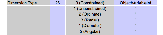
Try GetObjectVariableInt(H1,26).
From the Vectorscript Appendix:

-
I think it is probably easier to just let VW continue to use all of the new prefs files it has created and reset the VW and Document preferences to your liking.
If the preference files are missing, VW just creates new ones with the default values.
-
I don't understand the problem. Can you please explain differently? What do you mean by "warped around my Resource Manager"?
Custom Search IFC records
in Vectorscript
Posted
Can you attach a sample file with an instance of the Tekla Bolt with the IFC record attached? Or tell me a simple way to create a file with this object type so I can see what is happening?