AnotherLD
-
Posts
10 -
Joined
-
Last visited
-
@Roy Wimpenny The long term solution is for Vectorworks to fix the bugs in there code. This is absolutely a bug and needs to be addressed. For now, you can import symbols and other objects from one VWX file to another. All you have to do is have both of them open at the same time, or to have one of the files saved under your favorites tab. Then you can pluck those symbols that are already fixed from your earlier file. Also, as for this not working subsequent times, can you elaborate? I never got this to work on 3D only truss, I had to delete those symbols and reimport the 2D/3D symbols from the library and then regenerate the 3D only truss. That got it fixed. Further, try playing around with the objects rotation inside 3D components. I saw on other posts some people had success with that.
-
@Roy Wimpenny Yes, that is expected behavior. Ya see, there you are right clicking on the truss objects in the VWX library. Those items can never be edited because they act as a sort of default. Any time you click on one of those objects and use it in your drawing there is an automatic import process which pulls a copy of that symbol into your drawing. The objects in your model space then reference to the symbol as it is in your drawing, not to the symbol as it is in the VWX library. That is the point of resource manager, is to allow you to have edited symbols and other objects on a per drawing basis. Notice in my image below that I am in the resource manager and that I have selected the file I am currently working on (untitled 1). Since I have used that specific truss symbol in my drawing it now shows up under this file name and I can edit it to suit my needs.
.thumb.png.75266735c30baaeceeb620c0418f7d70.png)
-
@Roy Wimpenny Just for clarity sake, I did not mean right clicking on the truss object in the model space and clicking edit. That will not get you what you need. It will throw the error you described because no truss object is "editable" in that sense of the word. That method is trying to edit values that are directly attached to the truss, and truss only really has position information. Rather, open up your resource manager and navigate in there to the truss symbol you are trying to use. Right click on the symbol in the resource manager there and in the drop down menu one of your options should be to "edit 3D components." That is how you access the fix I descried earlier. If you already knew that, ignore me.
-
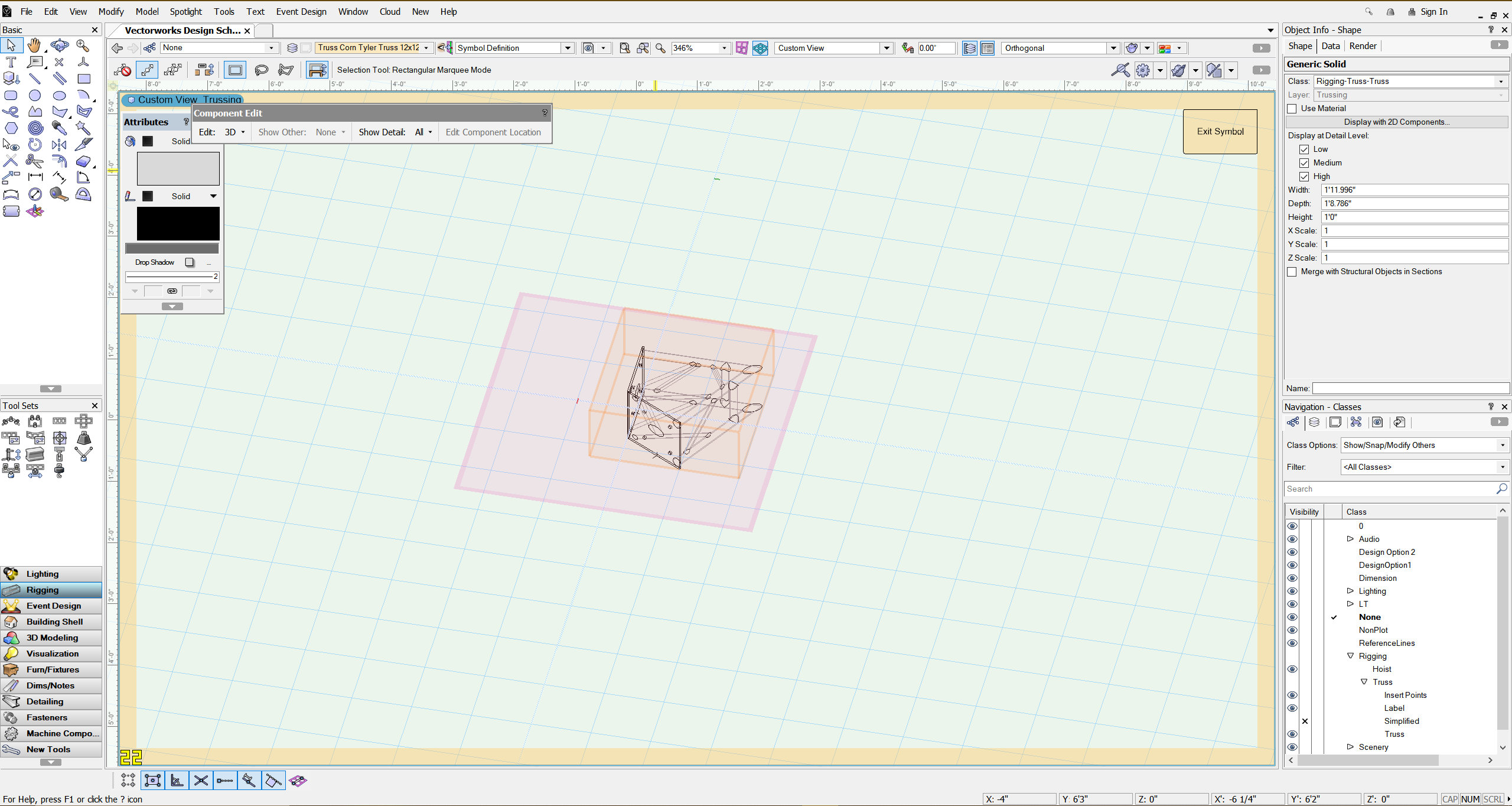
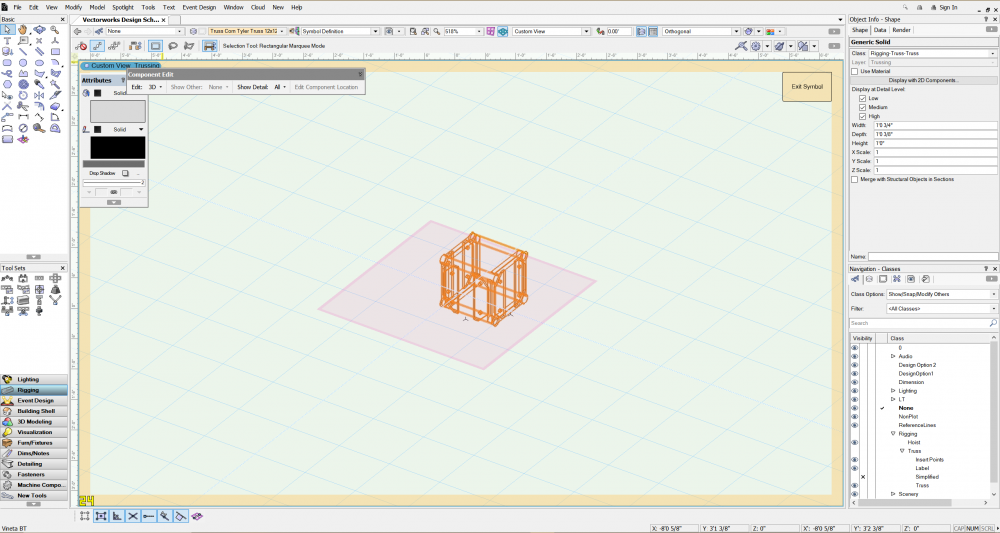
@JustinVH @MartinBlomberg I believe I fixed the problem. Go into your resource manager and right click the truss to edit 3D components. Then select the object. In the OIP go to the render tab. Set the texture field to "texture" and map any old texture in the file to that truss. Now exit the symbol and BOOM, your truss object should be visible. If you don't like the look or color of the texture you chose that is fine, just go straight back into the 3D components and this time set the texture to "None." when you exit editing that symbol your truss should be grey and still visible. Explanation/Theory: It appears that these truss objects are linked to an a aluminum texture file that is either no longer present, or it is not functioning properly. So when the truss tries to call upon the aluminum texture and use it for its visualization it literally gets nothingness; a transparency. So by manually mapping the thing to a random texture and then remapping it to "nothing" you have manually reset the system and now its no longer searching for some aluminum texture that is not present. Also keep in mind that truss objects come in as 2D/3D symbols. If you want truss objects that are just 3D you will have to apply this fix to its original part straight out of the truss library, then delete the 3D only symbol in resource manager, then check the little check box in the OIP that says "Draw 3D only" and then go to top/Plan view. That process will regenerate your 3D only truss symbols with the applied fix. So far this little dance has fixed all my invisible truss. I hope the information doesn't come too late for your project and I hope its effective for you as well. Cheers all, and happy holidays.
-
Hello All, I am having the exact same issues, but I have some added info. When I go to edit the 3D elements of the truss symbols that are invisible, I find they are inside some sort of bounding box. When you select the 3D elements the object type is generic sold. I believe this is normal because the truss objects that are working correctly are also generic solids. However, the truss symbols that are working do not have any bounding box around them. They just highlight the edges and geometry of the solid instead of being inside a box. I do not know what these bounding boxes might mean, but I would bet they are somehow connected to the problem. Please respond if anyone finds solutions. I would greatly appreciate it.

-
Help with Tutorial on data visualization and schematic views
AnotherLD replied to AnotherLD's topic in 3D Printing
Well would you look at that... My bad. I will head on over to the proper forum now. Many thanks. Edit: just noticed that your the original creator! your tutorial was phenomenal and I utterly love your workflow. Thank you for putting in the time and effort to make this video. I am a lighting design graduate student who is still working on his drafting skills and I feel like you may have catapulted me ahead by quite a few steps. Thank you again for sharing your knowledge. I believe as a student I can update to 2021 so I will attempt to follow along with you again once I have it downloaded. Best, Conner Jones- 2 replies
-
- 1
-

-
- data visulization
- lighting design
- (and 3 more)
-
Help with Tutorial on data visualization and schematic views
AnotherLD posted a topic in 3D Printing
Hello all, I am an LD working through a fantastic tutorial I found on YouTube and I have a plethora of questions. If anyone can assist me, I would appreciate it. Mostly I am unable to find the same commands that are shown here, and I wonder if they have simply been moved somewhere else in my version, or if they are in fact removed and replaced by different tools. I am running Vectorworks 2020 SP5. If you can answer any of the following questions, or provide your own methods, I would be grateful. At 5:53 in the video he makes reference to using data visualization to apply a more grey texture to his lighting devices. My data visualization options are limited to only "Pen" and "Fill" attributes. I do not have an option to change an objects texture as he displays here. Can anyone tell me how to use data visualization to change the texture of 3D objects similarly to how its done in the video? I would like to be able to switch the lights from grey to black rather quickly. at 6:40 & 11:50 he demonstrates how he has drawn a NURBS curve through a box to create a hanging position with a center line. This solves an age old problem for me because it should allow me to place my lights on the center of a pipe instead of choosing the US or DS edged and attempting to remain consistent. However, when I follow his example and do this in top/Plan view the lights do not snap to the center line (the NURBS curve). Instead if I want the lighting instrument tool to snap to a line I have to go back to smart cursor settings and turn "nearest point on edge" back on. This is a problem because now I can snap to the front and back of the pipe again. This makes consistently grabbing the center rather hard. Further, I cannot get my cursor to turn red as his does and the lights C-clamps are slightly above the pipe rather that centered on it. It is as if they are snapping to the top surface instead of the NURBS line in the center of my hanging position. Is there any way to snap to only the NURBS curve or otherwise center the C-clamp of the lights on the lighting pipe? At 15:05 he shows off the "remove accessory mode" in the lighting accessory tool. I simply do not have this mode. When I click on the tool I only have a drop down box asking me to select an accessory. I cannot select a "remove accessory" mode. I would like the ability to do what he does here and remove the C-clamps of fixtures at will. I often have to do this by modifying/creating new versions of symbols from the stock lighting symbols. That process is rather labor intensive and I would prefer any other method other than crating a whole new lighting device every time I need a light on a base plate or side arm. The tutorial in question is here: -
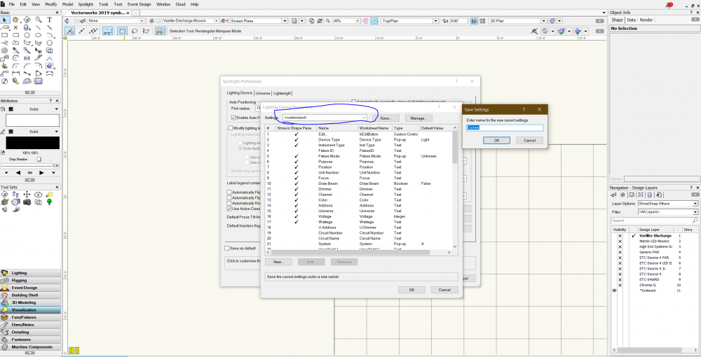
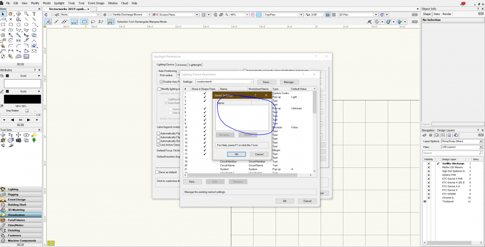
Hello all, I am running vectorworks designer 2019 educational version, SP4, Build 490894 Here's my problem. If you go to (file>Document settings>Spotlight preferences>Lighting Device Parameters ) You will get a dialogue box which allows me to sort all the parameters how I like them. Yay! but when I go to save those settings... nothing happens. I click save, I get a dialogue box asking for a name for the settings, I enter something like Conner, and then I click save. The dialogue box goes away, but there is nothing in the settings drop down or the manage screen, both are just plain blank. So why is it not saving my settings? or am I missing something? I googled my issue and could not find anyone with my same problem. Does it matter that I am running student edition? Any help is much appreciated!
-
Hey Hans, It is a great time to buy a 3D printer. There are some really hassle free machines on the market that can produce great results. However, what you need to understand is that buying a printer means, at the bare miumum: 1. learning to use a slicing software like Cura or PrusaSlicer 2. Spending a few days initially calibrating the machine 3. Spending enough money to get an out of the box great device Most of the 3D printer world is still built around buying a cheap device and upgrading it over time to make it wonderful. If your company wants something they can use right now, its gonna cost a little more, but it need not cost a fortune. The selection of a device depends mostly on your budget range and size needs, but one printer that is well know for minimal fuss and high accuracy is the Prusa i3 Mk3 https://shop.prusa3d.com/en/3d-printers/181-original-prusa-i3-mk3-3d-printer.html If I needed a detail oriented 3D printer with high reliability, this would be my first choice. This is because above all else, this printer is known for working well in a print farm setting. In terms of work flow, I build all my models in VW and save them as a VW file type. Then I export them as STL or as 3MF for slicing (3MF is preferred). Run that file through a slicer software like PrusaSlicer or Cura and then you should have the G-code ready to be printed. Most Printers do not have any networking capabilities stock, but you can easily network a printer over Wifi using a $30 Raspbery pi3 B+ and a software called Octoprint. Once the printer is networked over Wifi, it becomes trivially easy to send files and make prints, even from multiple different desks or offices. Hope some of that helps.
-
Hello all, I am in the market for a new laptop as mine is four years old and is starting to do some concerning crashing. I currently run an alienware 15 R3, which is a heavy beast. I have shopped around and landed on either a Dell XPS 15 or a HP Spectre X360 (Specs below.) I love these devices because they are thinner and lighter than my current laptop, they have a touchscreen which works well with Eos, and they have great battery life. However I am concerned that they wont be good enough in terms of graphics. My current laptop runs a GTX 1060-6GB. That GPU outpaces the one in these suggested laptops (GTX 1650) by nearly a 30% margin. That said, I have seen people run Vectorworks for 3D applications like mine on a 16" macbook pro. A 16" MBP has a mere 5300M as a GPU and they seem to be doing just fine despite the fact that the 5300M and is outpaced by my current GTX-1060 by a whopping 60% margin. I would conclude that a GTX-1650 is probably adequate for my specific needs, but I am unsure. Further, the newer CPU's in these suggested machines offer a performance boost of about 24%. I would in total, be trading down some GPU power to gain lighter weight, better battery life, better display, and more CPU power. Do you think this is worth it? If your wondering where I got the comparison numbers: https://www.userbenchmark.com/ What I do: I am a lighting designer who uses vectorworks spotlight to create 2D light plots and 3D entertainment venues I do a lot of 3D work in open GL, hidden line, or wireframe I do not use renderworks and I do not render any 3D images for export I do not use 3D textures I only model things in 3D so that I can see a realistic cross section of a light fixtures light beam in the wireframe "Draw beam" mode. My questions: 1. Is a GTX 1650-4GB sufficient for these applications? Take into account the laptops display is 4K 2. Do you think the increased CPU power of these laptops will make any real difference? +24% Laptops in question: Current model, Alienware 15 R3 CPU: 7700HQ GPU: GTX-1060-6GB RAM: 16GB 2400Mhz Display: 1920X1080 60Hz 15.6" Storage: 1tb 7200RPM + 256gb SSD Option 1, Dell XPS 15 7590 CPU: 9750H GPU: GTX-1650-4GB RAM: 16GB 2666Mhz Display: 3840X2160 60Hz 15.6" Storage: 1tb SSD Option 2, HP Spectre X360 CPU: 9750H GPU: GTX-1650-4GB RAM: 16GB 2666Mhz Display: 3840X2160 60Hz 15.6" Storage: 1tb SSD Thank you all for any advice or discussions. Alternative device recommendations are welcome.
.png.b7a8747c81ca1d58fc53998d86c6a2eb.png)