


Conrad Preen
-
Posts
1,023 -
Joined
-
Last visited
Content Type
Profiles
Forums
Events
Articles
Marionette
Store
Posts posted by Conrad Preen
-
-
Hi Daniel
me again! So, these enclosures are a bit like a rack with a different look, and without RU heights... so in a way they could be a variation on the rack objects where equipment is placed by the designer to-scale. That way an elevation view of the enclosure gives an installer guidance on where to mount stuff. I'm beginning to like the idea!!!
Conrad
-
Nice idea though...
-
What we are asking for here is to link up data from more than one table. In SQL this is called a JOIN. Vectorworks can't do a JOIN right now.
I agree completely that reports like these would be very useful. I will make a bid for this, but I also want it done right. So please be patient. It will happen. The more voices are heard here asking for this the better.
Thanks everyone!
Conrad
-
 1
1
-
-
Ok. I'll hold that thought...
Thanks!
-
Thanks Daniel - got it!
This is interesting but begs the question as to how we establish location addresses in these enclosures. For example do we have some equivalent of the rack U?
Conrad
-
Hi Daniel
That sounds interesting. Can you post me a link so I can take a look at these enclosures?
Conrad
-
Hi,
You can add the ODBC > Database menu to your workspace and link your database using this. You will need to install and set up the ODBC driver for your particular database. There a whole section on this in the online help. As far as UIDs go, we now link our objects internally using other methods so I'd have to know a bit more about what you are trying to do in order to help. Suggest you start by getting the database connection and then see what that can do for you.
If you get stuck ask me.
Conrad
-
As things stand the Vectorworks does not have a relational database. You cannot create a query a.k.a criteria that links the properties of more than one object. The good thing about this is that it is simple. The bad thing about this is that it is simple! ConnectCAD reveals this underlying issue because it is dealing with connected objects.
ConnectCAD works around this limitation by having the Circuit object pull in data from connected sockets and their devices. But fixing this properly needs changes at a more fundamental level than ConnectCAD. So the more votes we get for this the better.
Meanwhile, it is well worth taking a look at Marionette. This gives you a very neat visual scripting environment which is ideal for automating your specific workflows.
Conrad
-
Hi Daniel,
To be honest with you nothing really great springs to my mind. It's one of these things that is easy to draw but hard to automate. The destination arrow label is the problem.
Conrad
-
Snap grid controls the size of ConnectCAD schematic objects like device and sockets.
this leaves you free to draw schematics at any scale. Event planners love this because they can draw directly on floor plans. So what's the catch?
If you want to customise the symbols used in sockets and device you need to be aware of the scaling. The easy way is to first set the snap grid to 4mm that way the scaling is 1:1. Do all your editing with this grid then when you are happy with the result set the snap grid to the value you want before you save your new template.
If you have existing symbols created on say 1/8" grid then you can use the Scale Objects with a scale factor of 4mm / 1/8" to adjust the content to a 4mm basis. Then set the snap grid to your favorite value.
Schematics in fact are Not to Scale drawings. The absolute size of objects doesn't matter provided the proportions and text sizes look right.
-
@switchonet This particular command is in my opinion so specialised that it is rarely useful. I should know - I wrote it 🤣. It was designed to help a very difficult project that involved trying to reconstruct the system schematic diagrams from the cabling. What had happened was that an employee left taking all his notes of years of modifications and installations with him. Bit of a nightmare really. So what should your expectations be...?
A cable list only has information about connected sockets and their device names. It doesn't know what is a sensible order to draw those sockets. So there isn't a lot to work with. And to make the result decent needs a lot of user intervention.But... over in my laboratory I got a command that you're really going to like - stay tuned for our new release this Autumn!
Conrad
-
Create Devices from List will be renamed Create Devices from Cable List.
It's a command that came out of a reverse engineering task the purpose of which was to recreate drawings from a cabling survey.
Conrad
-
The physical locations of schematic devices are defined by placing equipment item objects on to-scale drawings of your rack elevations or on floor plans. The command Update Rack Elevation does a bulk create of Equipment for all schematic devices on the current layer, placing the Equipment Items on a layer called Rack Elevation. Then you can either drag them into racks or move them to a floor plan layer. As you move your equipment around it automatically detects if it's in a rack or a room and also update corresponding devices (i.e. devices with the same name as the equipment).
Update Rack Elevation is smart - it checks for existing equipment as it creates, so you won't get duplicates. It also leaves selected any equipment that has no device. So, you can run Update Rack Elevation multiple times in your design cycle to keep the schematic and physical worlds in sync.
Hope that helps. Don't forget to check out the online help too.
Conrad
-
Hi Ross
I think the Connector Panel schematic device is your friend here. Create these on your power schematic, then do Update Rack Elevation to create the panels as physical equipment items. You can then use the Get Connectors button in the Object Info Palette to add the physical connector symbols to your panels. Double-click the panel equipment item to enter the panel and add any extra graphics / position connectors etc. In terms of 3D modelling you can check the Use Symbol box in the Object Info Palette and select a symbol to display.
Normally you'd import the 3D equipment model from a file supplied by the manufacturer or create your own. It's up to you how detailed you want the drawing to be.
Hope that helps.
Conrad
-
Hi Daniel
The menu item you are looking for is called ConnectCAD Report. If I'm adding it to a menu containing other items I add a separator above it for clarity. Hope this helps.
Conrad
-
Thanks for the feedback !!!
Conrad
-
Hi Daniel,
This is something that Vectorworks native reports can't do I think. A script would be the way accomplish this. I'm collecting up these case to refer them to the team working on reports. And I'll try and find time to rustle up a script. Meanwhile do take a look at Marionette - it's a great way to automate stuff without the pain of writing code.
Happy New Year!
Conrad
-
Hi Thomas,
Happy New Year! Right now Vectorworks database cannot do JOINs so unfortunately the answer is no 😐. There are some limitations to reports as things stand. I will mention this request to the team involved.
transfer custom parameters? you could write a script that does this. Tell me a bit more about what you are trying to do.
Conrad
-
Hi Kevin
Happy New Year! That's not exactly a bug. The name is the way that devices are related to their physical equipment. And you can have more than one schematic device referencing the same piece of equipment. Duplicate-modify is a powerful workflow in ConnectCAD. You can create part of a schematic say an input processing chain, then duplicate this to create similar channels, rename the devices and boom you're done. Now what happens if that device name change was propagated to the equipment ?
Quite often when you are re-working an existing system you will define pieces of equipment that aren't the schematic and that's normal. Update Rack Elevation leaves these selected so you can just hit delete and get rid of them. But I don't think we can flag them as errors.
Good to debate these things. Not sure there's a case to change them yet.
Thanks, and all the best!
Conrad
-
Hi Daniel
I love a challenge! Happy New Year !!!
Conrad
-
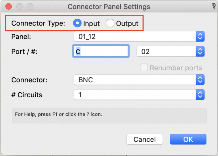
@jdepaepe In Vectorworks 2021 just select the devices you want to change, click the Edit Device Array button in the Object Info Palette and choose Input or Output in the dialog. There isn't a foolproof way to determine how a connector is being used so you have to set it.
-
Thanks @jdepaepe
Crowd-sourcing with curation is certainly a way to go. I will keep that in mind. To make a case for this I would need to get an idea of the possible income. So supposing for a moment that this service exists, how many dollars per month would you be happy to pay for it? or how much per equipment model to download?
Let's see if there is a real proposition here. Feel free to PM me if you prefer.
Conrad
-
@Luther Core Happy New Year to you also!
Here is a video of placing blank panels. It is fairly quick and works as far as I can see... just simple 2D drag and drop. The blank panel is just another Equipment Item - nothing really special.
@jdepaepe and @Luther Core Thanks for clarifying this. Regarding richer more pictorial content... as I've said before you can add as much detail as you like to Devices and Equipment Items. And you can save these objects as symbols. The symbols are colored red in the Resource Manager to indicate that they become parametric objects when placed on the drawing. Using the Resource Manager you can access symbols from other documents, and keep frequently-used symbols in a favorite document as a personal library.
Vectorworks may in the future add extra resources to produce this kind of pictorial content. But you do have to appreciate that keeping such content reliably up to date over the vast range of products that appear in ConnectCAD designs is a Herculean task. Let me put it to you. Would you be prepared to pay an extra subscription for access to such a library? and how much would you consider reasonable?
Conrad
-
Dear @jdepaepe
By Device in ConnectCAD we mean the device as represented in a schematic drawing. You can add images to Devices by double-clicking the device to enter its group. Anything you add in there is drawn as part of the device. You can save any device as a symbol and re-use it.
By Equipment Item we mean the physical device on a to-scale drawing e.g. a rack elevation. Again you can double-click an Equipment Item to enter its group and add images etc. You can save any Equipment Item as a symbol and re-use it. Schematic Devices refer to the Equipment Item that has the same Name, Many devices can refer to one Equipment Item. We use Equipment Items to define the physical location of devices in racks and rooms.
So in this context, where would the image be that you want to appear automatically? in the Device, or in the Equipment Item?
Conrad

custom socket label
in ConnectCAD
Posted
Hi @switchonet
These symbol name selections are fixed in the code of the object. The reason being that we need specific symbols for each orientation (L, R, T, B) and each type (IN, IO, OUT). Tell me a bit more about what you want to do. Maybe we can find a way without changing the code?
Conrad