


HWood
-
Posts
36 -
Joined
-
Last visited
Content Type
Profiles
Forums
Events
Articles
Marionette
Store
Posts posted by HWood
-
-
- Popular Post
- Popular Post
Please please revert to the 2023 icons! The new ones are barely legible. With their smaller fuzzy shapes and lack of colour - it's so hard to find what we need. This is 'style' over substance!

-
 7
7
-
Please can someone tell me whether you can set up a Keynote Legend Style? Currently I have to change the text style for the heading and main text separately for EVERY legend to suit our company graphic standards! I just want the legend to come through in our font (Gill Sans) automatically! Thanks.
-
Hi, The guidance suggests the legend is created automatically on the annotations layer when you apply a data visualisation to a viewport - but it never appears for me anymore (it used to). Is this a known bug?!
-
I cannot edit the text of a Data Visualisation Legend - is this a known bug? It lets me edit the text, but when I press 'OK' it reverts to the previous text!
-
my clever colleague worked this out, so I hope it helps others. 2019 VECTORWORKS Useful Notes - areas calcs.pdf
-
1
-
-
I am trying to use Data Manager - I understand the principals of needing objects to have records attached. But how do I add these to a wall style for example?
The Vwx training on the subject just says - 'Attach a Custom Record...e.g. WALL DATA - parameters include Fire Ratings' but now how to add that Custom Record to the style....
I currently have to select the wall(s) and then go to the data tab and attach the record I want, which can easily lead to errors and is rather time consuming...
Regards
-
1
-
-
it would be really useful if design/drafting view could have colour by layer turned on, but when you move to the viewport it is turned off....! keep having to switch it on and off.
-
1
-
-
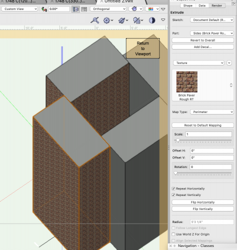
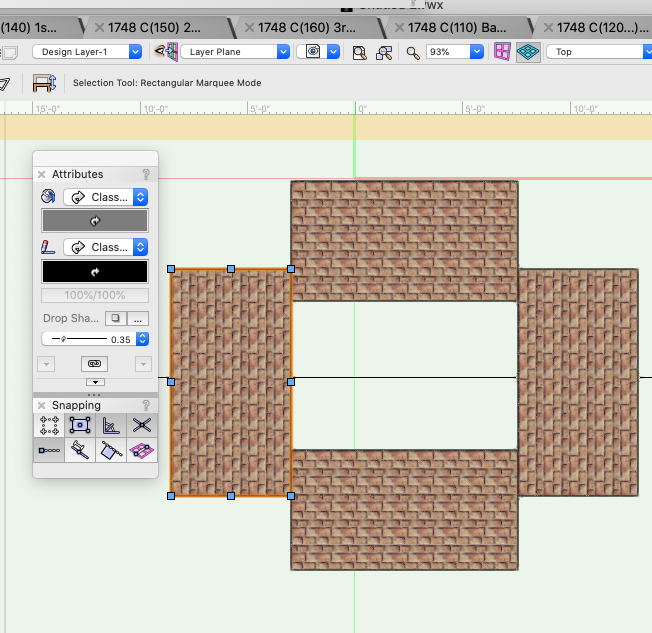
partial workaround for the plan attributes - just texture the sides of the extrusions.....but still...!
-
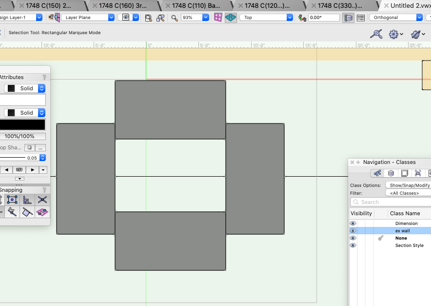
e.g. section style of grey fill and thick lines - when used on section viewport this is not seen - just think lines and white fill....or in plan when in the drafting view - class characteristics not visible, although the attributes palette shows them correctly.
I've had this slightly resolved in that the 'plan' characteristics apparently only appear if you render the plan as OpenGL - this seems very odd, to have to render all plans just to have the existing walls in grey with a thick line weight....but then if you want the wall to have a texture in 3D you can't have just grey in plan???

-
20 hours ago, Domas said:
Hello HWood!
This could be related with the navigation graphics issue that was around and most of the time was caused by compatibility issues. Now this was patched up with service packs.
Please give it a shot and go to Tools-Options-Vectorworks preferences. Open the Display tab and change the navigation graphics either from "Best performance" to "Good performance and Compatibility" or the other way around. If this will fix the issue don't worry working on the selected option this will most likley just improve the performance of Vectorworks.
This issue was fixed in Vectorworks a couple of Service pack's ago so to further look into this and to make sure that all navigation graphics modes would be working please update your Vectorworks to the latest service pack. If that is already done and you will still see issues, don't hesitate to contact the local distributor for further troubleshooting. Again just to remind you that there is should be absolutely no problems working on a different navigation graphics mode.
thank you @Domas we have tried this but it hasn't helped unfortunately. We are on the latest service pack for 2019. We have also tried opening it in 2020... 😞
-
Hi All,
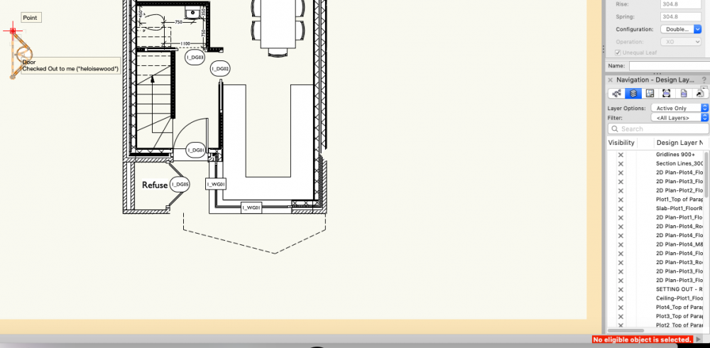
Is this a known issue? We've had parts of drawings disappearing for a few weeks now. Particularly from larger files, but both 3D models and 2D draughting. Sometimes the drawing is missing from one users computer, but visible on anothers. Sometimes we can see the orange box when we hover over it , but even if we click into annotations we can see nothing at all. The data is never recovered and we have to draw it again! Very concerned.
-
-
How do I "pull out the profiles and use them as Customs" please? We are struggling because we need to add UC203x203x86 and can't figure out how to add a custom shape!
-
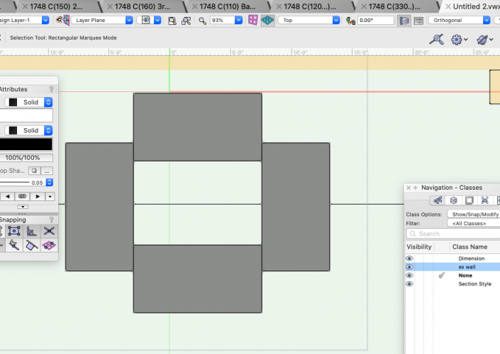
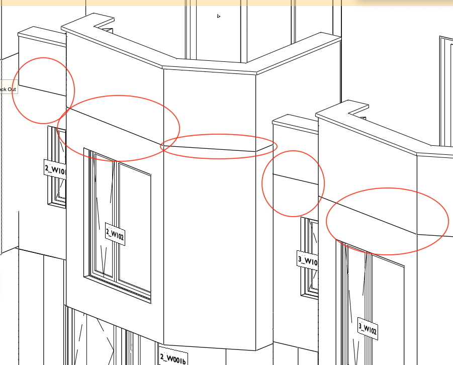
I can't seem to get rid of the line between levels/storeys - see attached. These are different wall types but they are aligned correctly in plan. there should be no line as it is a continuous brick elevation.

-
2
-
-
other than shouting across the office, is there not some way that one user could request that another user 'saves and commits'?!! I.e. a pop up notification on the screen? And when we add comments during 'save and commit' these do not seem to be given to the other users...
-
How do we do this? We include them on our window schedules usually. Currently we can't even select the rooflight in the roof, let alone add an ID tag and all the associated data tags required to populate the window schedule report....Thanks.
-
2
-
-
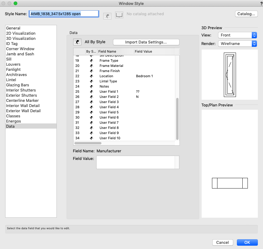
Hi, How do I assign a name to a user defined field in the door or window style options pallets? Currently they are User Field 1 etc....but that means that when I generate a door or window schedule report, they have incorrect headings/data - and it is hard to remember what each UF is for! Thanks...


-
On 7/11/2019 at 6:37 PM, Pat Stanford said:
I don't know if you know about editing data tags or not, so I am going to go step by step.
1. Start with a Tag Style that you like.
2. Select the Tag and convert to Unstyled.
3. Click the Edit Tag Layout... button at the bottom of the OIP (will only be active with an unsettled tag).
4. If you want an additional piece of text add it as a placeholder and leave selected. If you want to reuse the existing piece of text select it.
5. You should have it say Text in Tag Layout in the OIP.
6. Make sure the Use Dynamic Text check box is selected in the OIP and click the Define Text Field... button.
7. In the Define Tag Field dialog box, make sure the Calculated Field radio button is selected.
8. If there is already anything in the Current Tag Field Definition, delete it.
9. Set the Data Source to Object Parameters.
10. Set the Object Name to Door - #Door#
11. Set the Parameter Name to Door Fire Rating - #DoorFR#
12. Click the Add to Definition button.
13. Click the OK button
14. Click the Exit Tag Layout Edit button at the top right.
15. If it does not look the way you want, go back and edit again.
16. Once it looks like you want, choose the Style Pulldown from the OIP and choose New Plug-in Style from Unstyled Plug-in.
17. The style is now only in this file. Use the Resource Browser to put it into a Favorite or even better into the Default Content (directions elsewhere on the forum)
Ask again if you need additional help.
THANK YOU - this is very helpful. And the tag is added by just clicking on the ID tag tool in the pallet and then clicking on the door....super!
Now, how can I delete the tags I have already got on all the doors.... and then suddenly it has deleted all these new tags and says none of the doors are eligible!

-
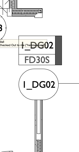
Does anyone know how to add a custom ID tag to a door so that it shows the fire rating on the plan - eg FD30S. I already have the door reference visible. Thanks.
-
17 hours ago, line-weight said:
I think possibly they need to be aligned properly so that VW knows they should be 'stuck together' rather than just next to each other.
But I think you also need to tick the box 'merge structural objects with same fill' to get rid of the line in section.
(By the way I would change 'line style' of 'objects beyond fill plane' to 'use class' and then specify a class with a thinner lineweight that then one used to draw the section plane.)
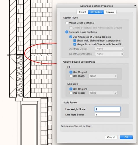
'Merge structural objects with the same fill'!! that was it, solved....after all that. thank you so much @line-weight
-
1
-
-
Thank you very much for your time! It happens at every junction between storeys and types of wall - I thought it must be something to do with a cap in the wall style....Do you think the section can be the same issue? The section viewport is cut automatically so it can't be that the walls are out of alignment at the cut plane....
-
thanks.......but eugh! 🙂
-
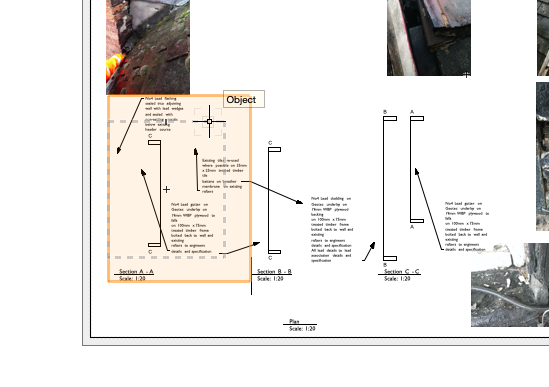
i've highlighted the unwanted lines in red in the sheet layer.
-
Thank you!!! Excellent!


Callout - Keynote Legend Missing
in Troubleshooting
Posted
Hi, Has anyone found a way to reliably use the keynote tool please? I am finding that most times the legend does not appear. It's not even in the Keynote legend dropdown box in the object info palette. It's so unreliable!