

Mat Caird
-
Posts
313 -
Joined
-
Last visited
Content Type
Profiles
Forums
Events
Articles
Marionette
Store
Posts posted by Mat Caird
-
-
Hi All, after writing out this long and boring question, I've sorted it out for myself - I'll leave it up, maybe someone can use it;
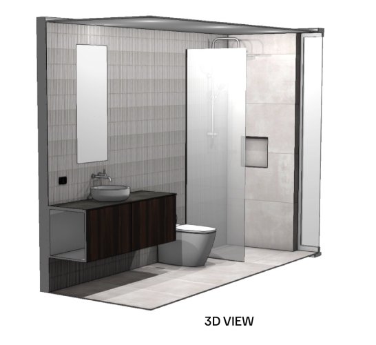
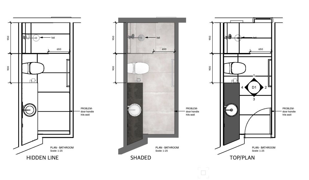
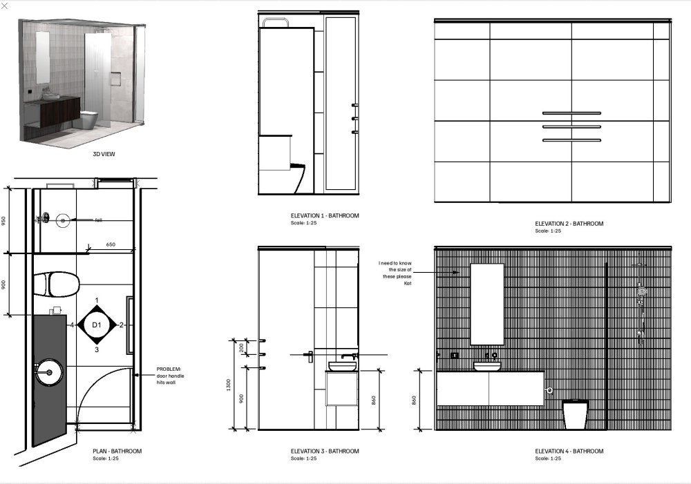
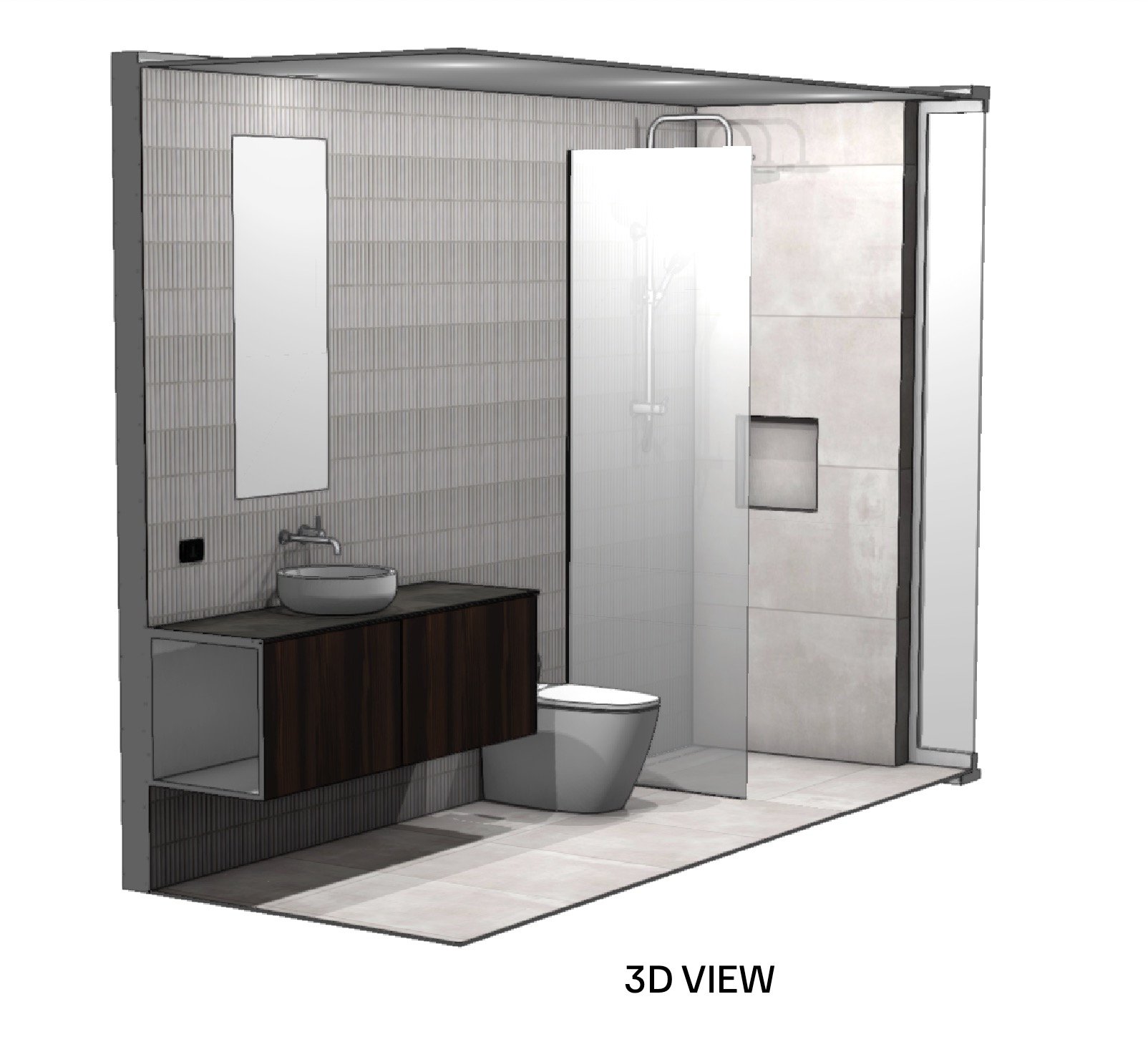
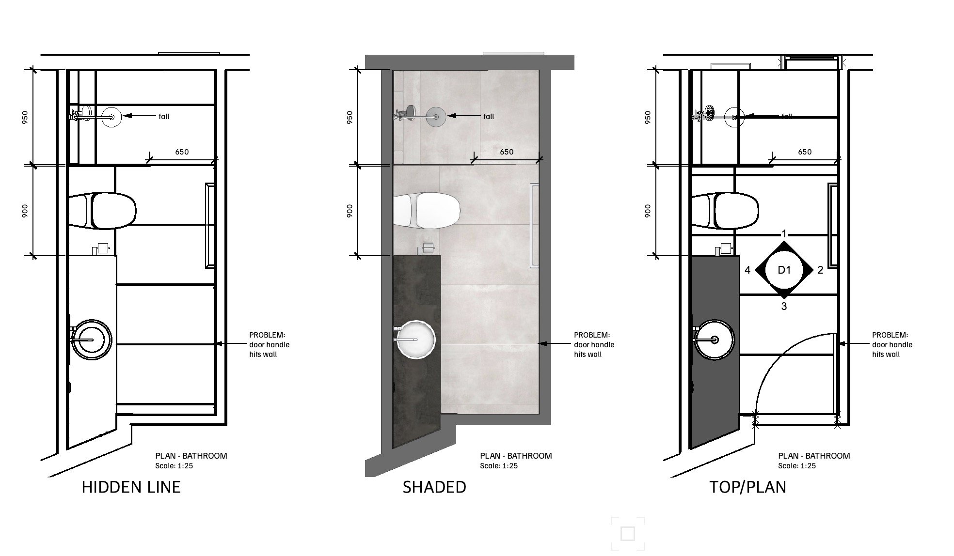
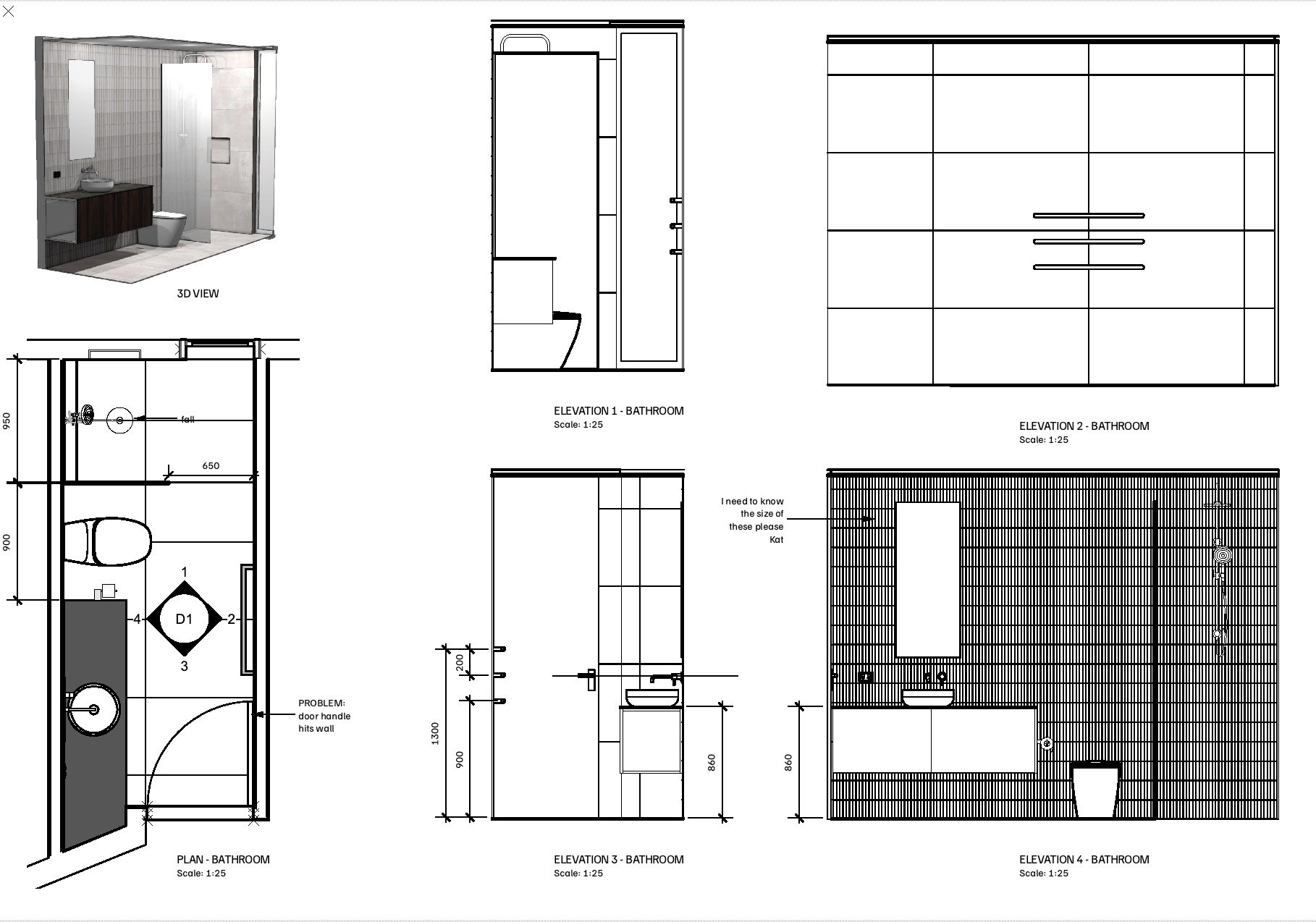
I'm trying to produce some internal bathroom drawings. I would like to render a 3d perspective view in Shaded mode, render the 4 walls as internal elevations in Hidden Line mode, and present the plan in Top/Plan (ie typical 2d mode). I have created a Renderworks Texture for the floor and wall tiles, and a hatch of the same tiles. I have assigned the hatch to the Surface Hatch in the Renderworks texture, and now I can successfully align the floor tiles so that the Shaded mode and Hidden Line modes match one-another.
I assign the hatch to the Floor object so it shows in Top/Plan view, and all three are aligned.
However, I then need to move the Renderworks texture so the proposed grout lines are where I would like them. Shaded mode and Hidden Line modes match, but the position of the Top/Plan hatch does not agree with the Renderworks texture. So I need to use the attribute mapping tool to move the Top/Plan hatch to agree with the Hidden Line Surface Hatch.
And after writing out this long and boring question, I think I've sorted it out for myself - position the Renderworks Texture in Shaded mode, using the Attributes Mapping Tool. Check that the alignment is correct in Hidden Line (even though I won't be presenting the plan drawing in Hidden Line). Switch to Top/Plan and use the Attributes Mapping Tool to align the hatch with the render work texture (it may help to draw some construction lines in shade mode first so I have something to snap to).
-
 1
1
-
-
Try changing the mapping type. I’ve been able to adjust the alignment in VW 2024
-
I'm having the same problem, every time I update my reference, it moves...
-
1
-
-
New blank file, create new render works texture, set transparency to Shadowcatcher, VW2024 hangs. Bug?
How do I file the bug to bug submit?
Regards, you all 🙂
-
1
-
-
Thanks guys.
-
1
-
-
Hi All
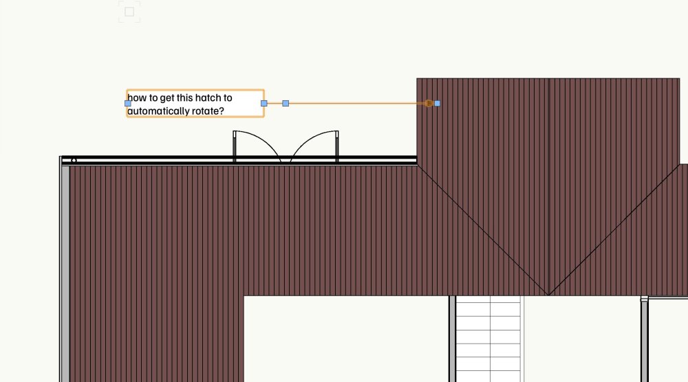
How to display a roof hatch in top/plan view, with the hatch correctly aligned with the roof plan? Using the roof tool, not the roof face tool.
I have the class options set to use at creation, with the fill set as the hatch, and the render texture surface hatch set to the same.
If I render the top view in hidden line, the hatch displays correctly as expected, so it's only top/plan view giving me grief.
Thanks,
-
Edit the viewport annotation and delete it. I’m guessing it’s a drawing label with some classes turned off, or maybe edited incorrectly.
-
2
-
-
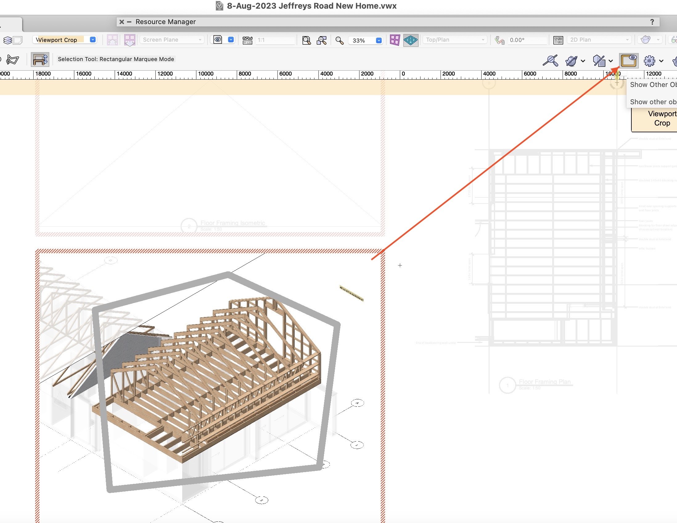
I think you're saying you've drawn a polyline on a sheet, over the top of a viewport. When you edit the viewport crop, the polyline disappears.
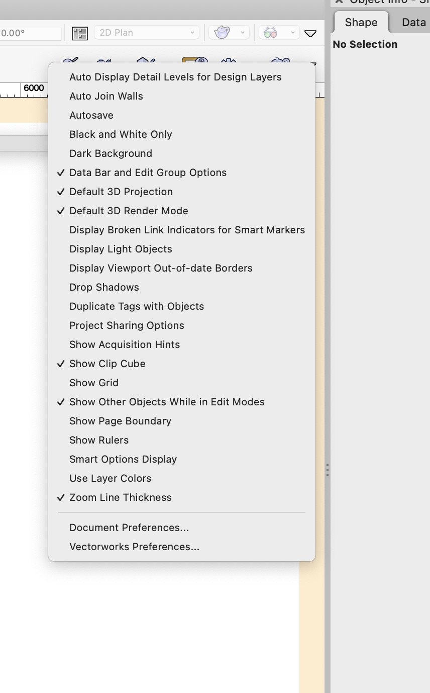
There's a button on the menu bar called "Show other objects while in edit modes". If you click that button, you should be able to see the polyline.
It's a useful feature when editing groups and symbols, but doesn't always work for some reason, if you have flipped symbols etc.
If it's not showing on your menu bar, there's a down arrow you can click on the far right, and choose it. See second screenshot.
Hope that helps, Mat

-
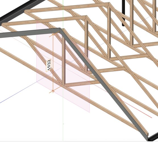
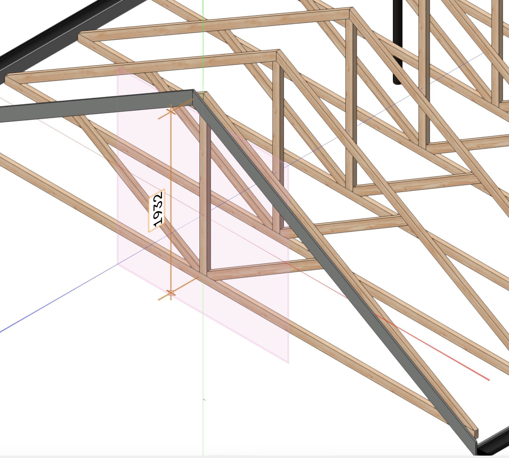
If you use the "set working plane" tool, click on the face of power socket, then it will draw the dimension aligned on that face.
The dimension will be in 3d, as per my screenshot below. I set the working plane to the face of the king post.
You may need to change to one of the other orthographic views to find the snap points. I find the snap points are more reliable in wireframe.
If you go back to top/plan view, it resets the working plane to top/plan, which is the same as Layer aligned. This won't affect the dimension you drew, but will for future, so you have to Set Working Plane once again.
HTH, Mat
-
1
-
-
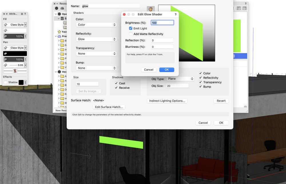
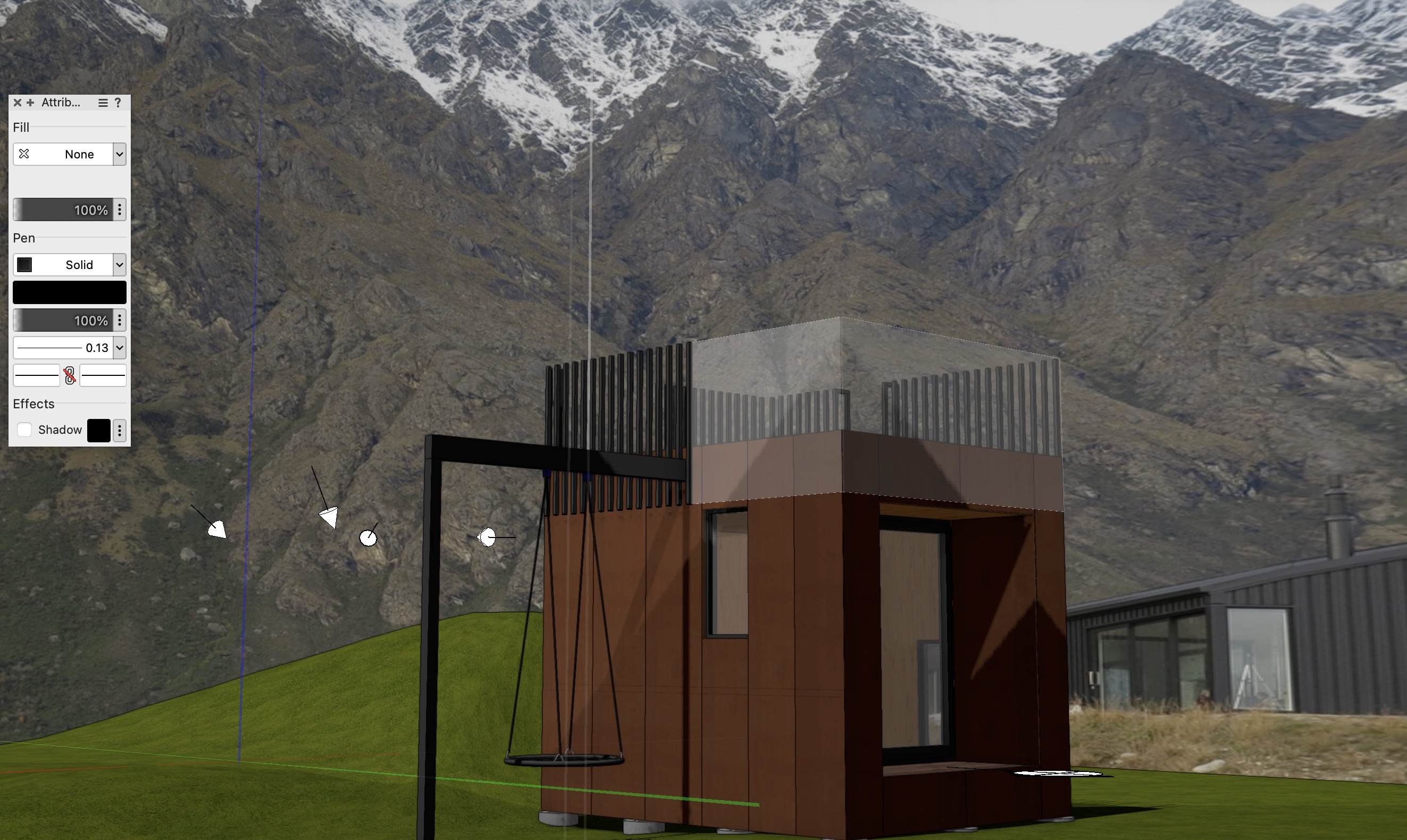
I got glow to work using shaded render mode - the effect was only obvious when I placed the object in the shadow. So that may be your problem. You could try View | Set Lighting options | and turn off Ambient Info (or turn the brightness down).
Another option will be to try selecting the line, then Modify | Convert | Convert to line light, or convert to area light and play around with that. I couldn't get this to work with shaded rendering so I had to use fast renderworks. It wasn't very convincing.
Maybe photoshop it....
-
Have the walls got height? Are the wall components classes turned off?
Do they render in shaded mode?
-
If your class options are set to display 'active only', and you create your viewport, the viewport will be created in the None class, but you may not be able to see it if None is not the active class, hence it will appear to you as if nothing has happened.
When I tried this, I could still see an orange bounding box, so it doesn't completely explain your problem.
-
Read this, it may help
-
Too Easy - thank you Pat
Regards, Mat
-
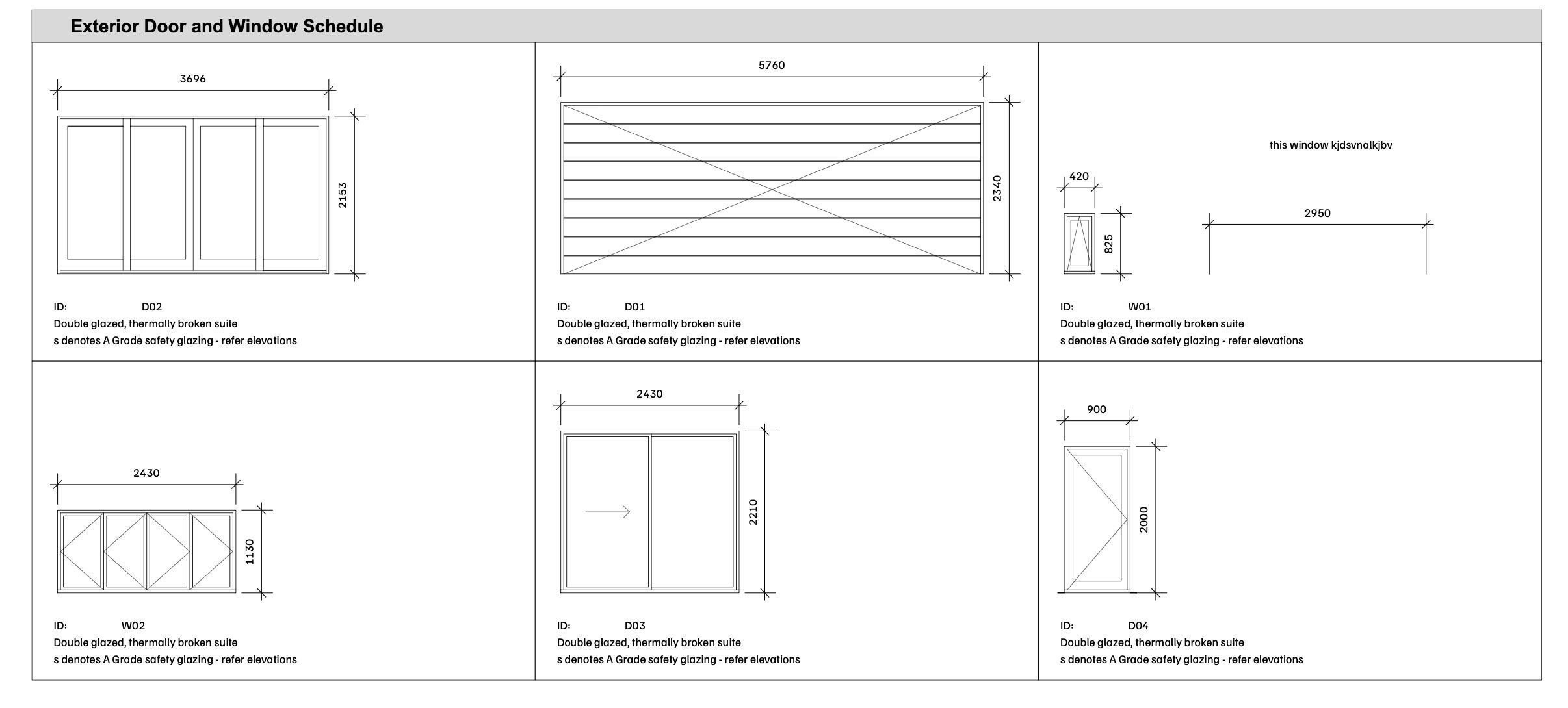
Hi All, how do I persuade the graphic legend tool to draw the windows at their correct sill heights, rather than on the floor like the doors would be?
TIA
Regards, Mat

-
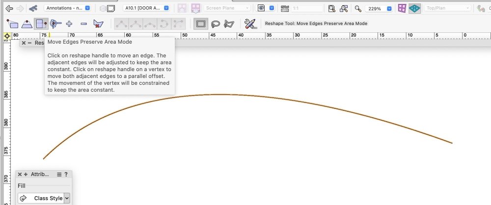
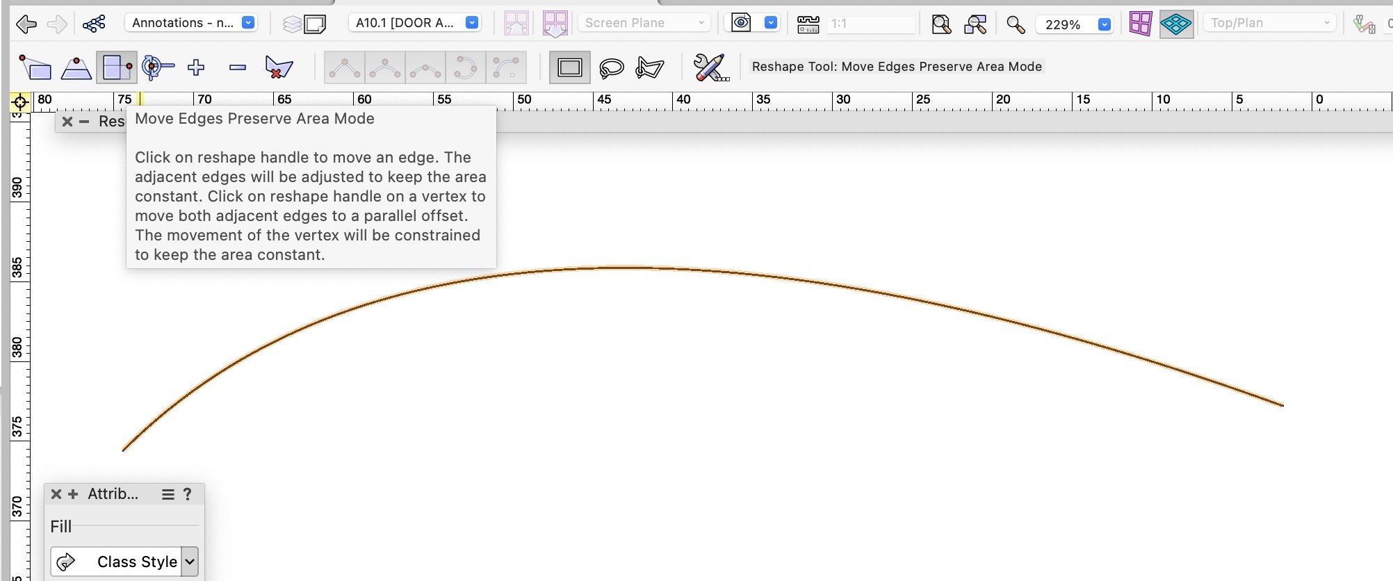
possibly this when using the selection tool (x);
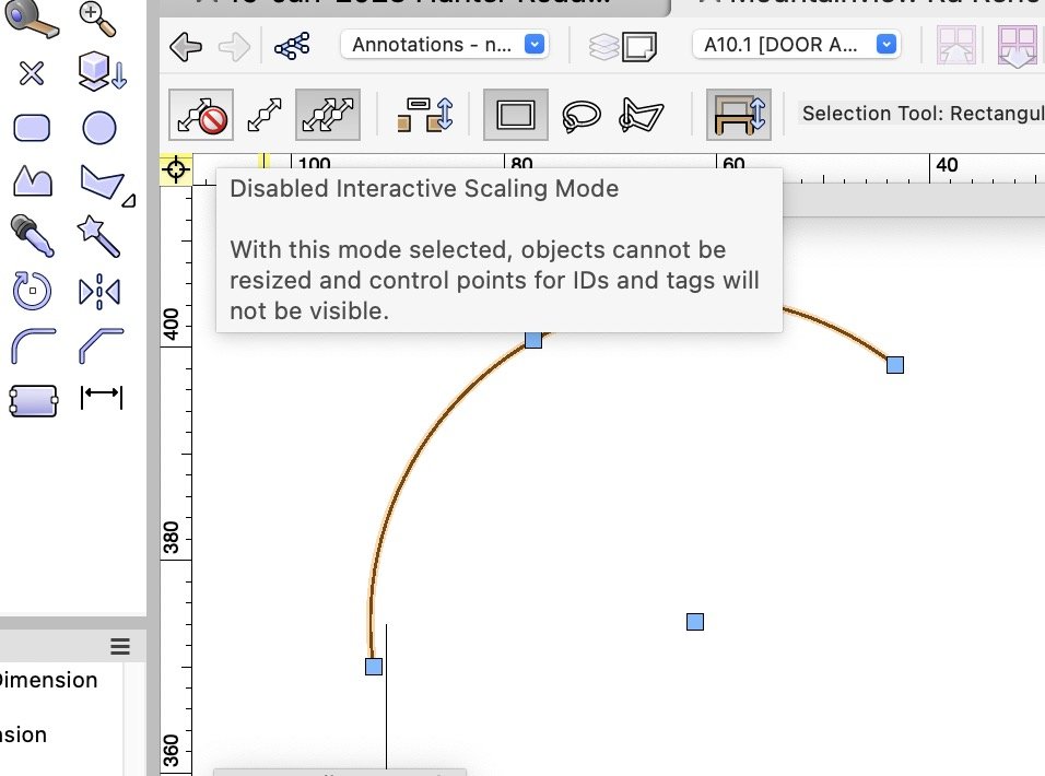
or this, when using the Reshape Tool (double click on the polyline);
-
Mine works fine and as expected;
I wish I could remember how to place the windows within the cell at their correct installation height (ie FFL to sill height) though.
HTH
Mat


-
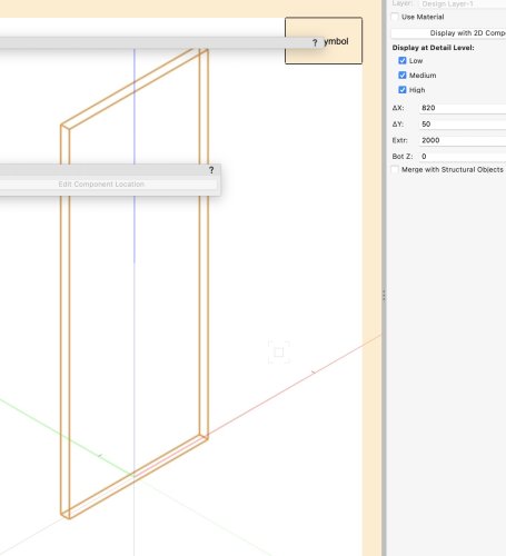
In the Resource browser, find your leaf symbol, right click and choose "edit 3d component"
Select the components and move them up in 3d so that the bottom of your component is at 0.
You may need to experiment a little with this to get the height correct.
-
Are the greyed files stored in the cloud? When you open them from the folder, they download first.
I use Dropbox on a Mac, and often files I’ve not worked on for a wee while get removed locally.
But I have the same experience as Tom W. Often grey files just open directly from VW
-
2
-
-
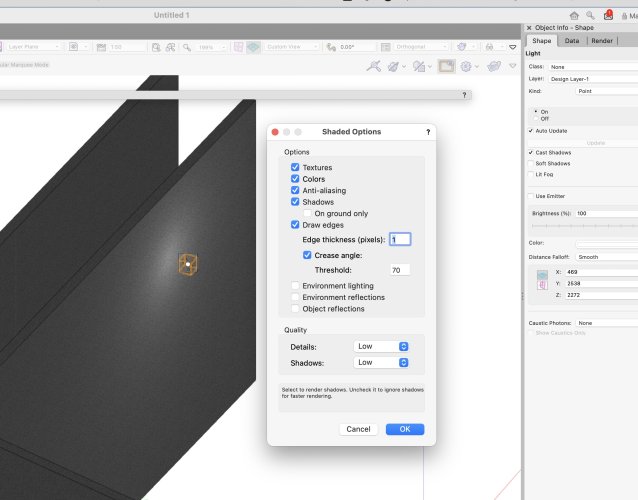
The Renderworks texture you're using for the walls (or ceilings etc) may have shadows turned off;
Also check under View | Rendering | Shaded Options, that Cast Shadows is on. (I'm assuming you're using shaded render mode)
Mat
-
2
-
-
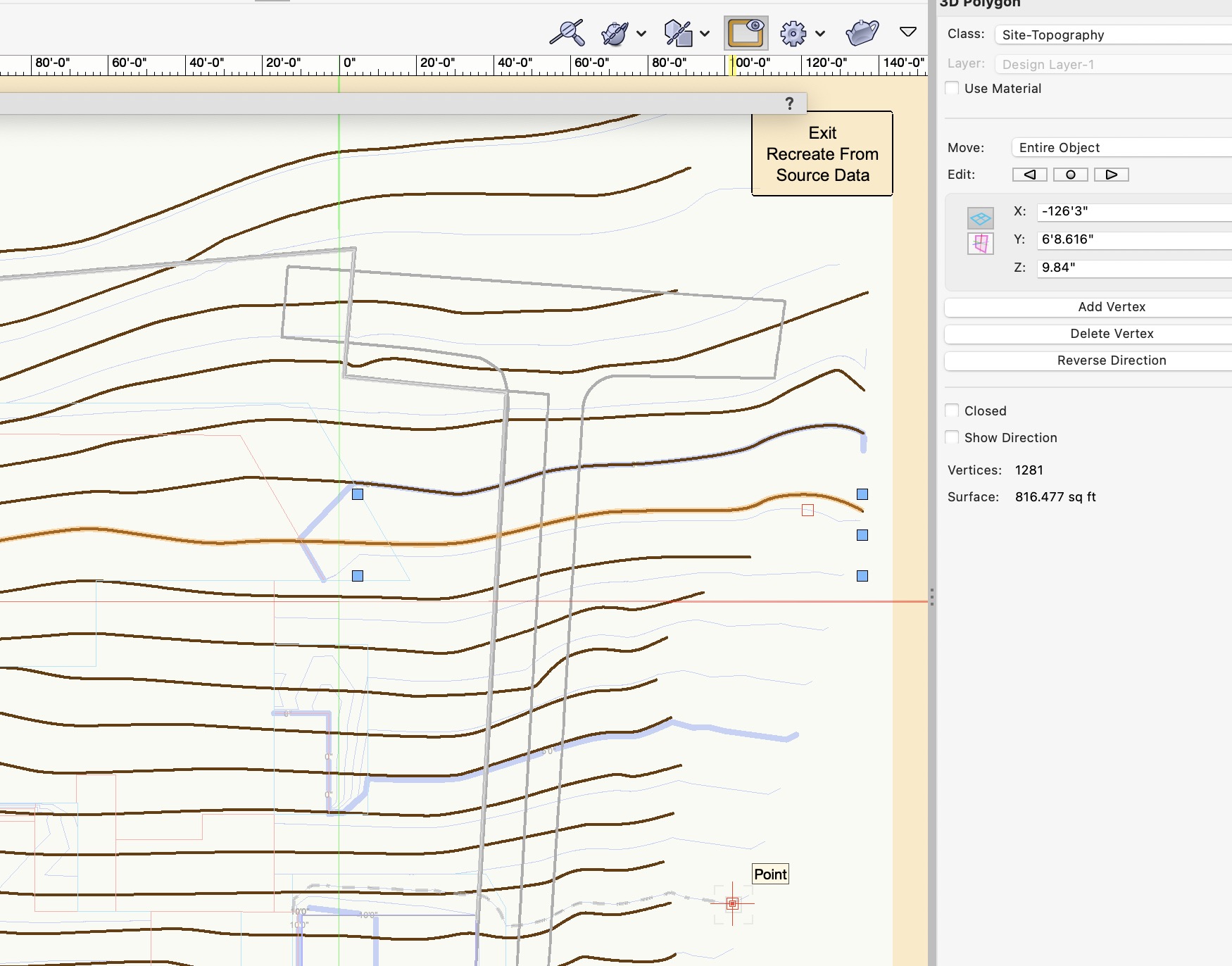
I found your site model to be very slow at updating. I selected "Recreate from source Data" and found your original 3d polygons had 800-1200 vertices each polygon.
My suggestion is to re-run your "Survey Input | 2d Polys to 3d Source data", and choose a segmentation length of 2 feet or something similar.
There might be another work-around if you didn't want to rerun the Survey Input. Maybe draw new simpler 3d polygons whilst in "Recreate from source Data". I haven't tried this.
Then, you can delete the contour labels using the Reshape Tool in Edit Site Label Position Mode (which I guess you already know). It will be a bit painful editing them, but nothing like currently. My experience is once they're deleted, they don't come back.
Mat

-
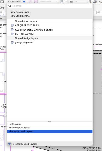
On the layers dropdown, chose "recently used layers"
Then use CMD up arrow or CMD down arrow
You may have to draw a line on the layer you want to show as recently used.
-
1
-
-
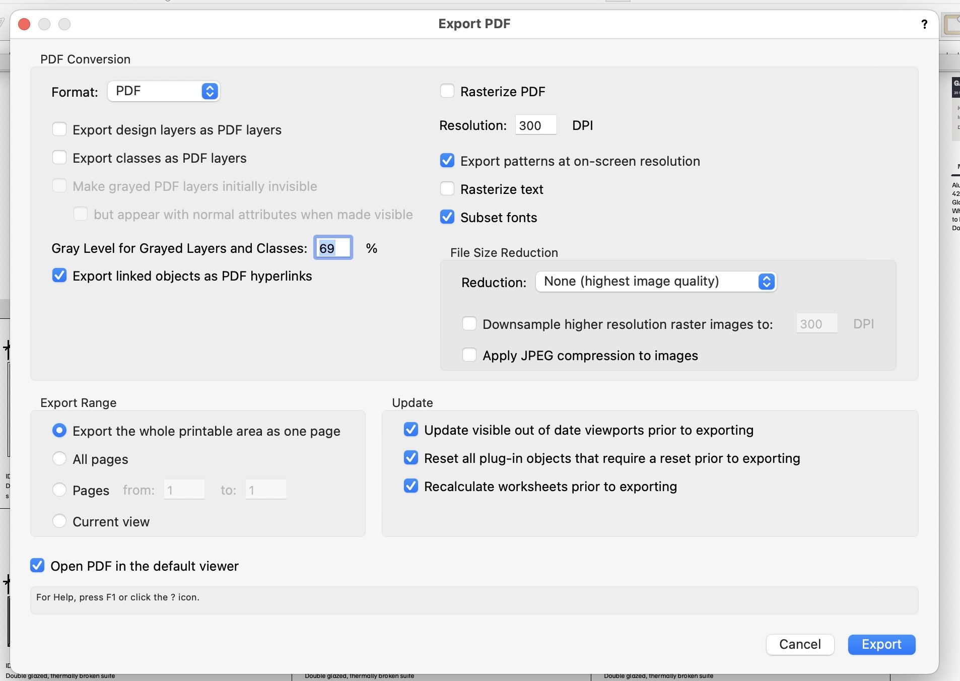
I did as you did, the custom modification tool.
I needed one colourful set of drawings for the builder, and one black and white set for the building consent authority.
The difficulty I had with the CM tool was that my viewports used different background render modes.
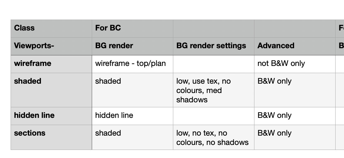
So I created classes for the various render modes, assigned the appropriate viewport to that class.
To keep track of the complexity, I made a quick table in Pages;

-
I tried the cylinder method - I spent 5-10 minutes on it.
This is using shaded rendering. I found the background image on the Internet. It is not a panoramic image.
Probably with a bit more work it would be acceptable.
To build the cylinder, draw a circle, I chose 100m diameter. Offset inward by 2m, then clip surface. (If you don't offset far enough ,you get "moire". Extrude this, then apply your texture. Muck around with scale and the attribute mapping tool.
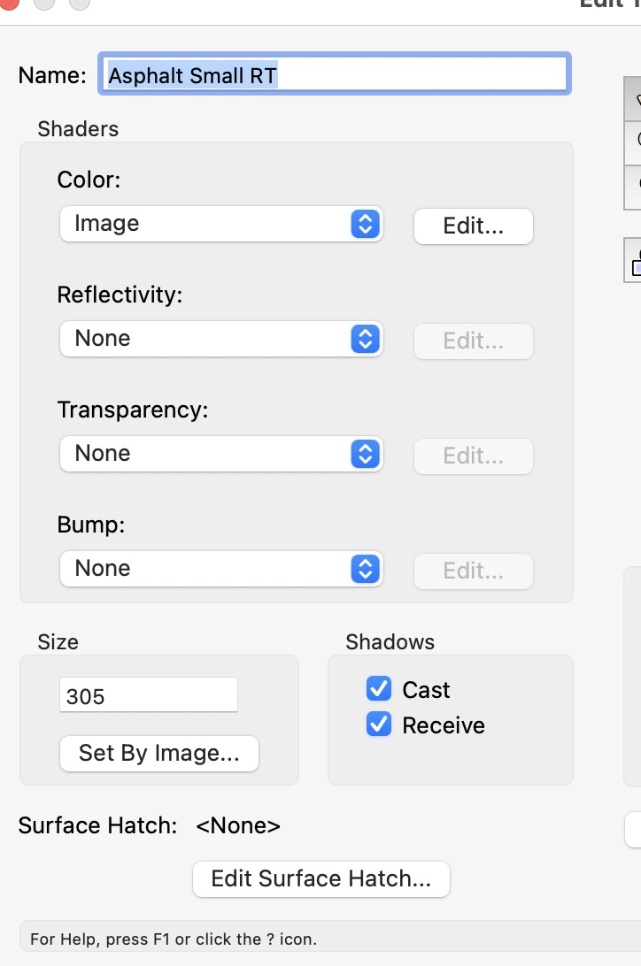
To build the texture: in the resource browser, "create new render works texture". In the Color field, choose image, and load your image. Untick Cast, and Receive shadows so that your Heliodon will function.
Have fun 🙂
 .
.
-
1
-


Graphic Legend, window sill heights
in Architecture
Posted
I think because you are using a style. Pull the dropdown beside “storefront window style” and choose edit style, or convert to unstyled.