


BG
-
Posts
382 -
Joined
-
Last visited
Content Type
Profiles
Forums
Events
Articles
Marionette
Store
Posts posted by BG
-
-
Hi. Am I correct in that, the only way to change the % of the slope faces once created, is either to delete the drains & re-create the slab drainage with a new slope % or manually adjust the valley slopes until you get close to the slope face % desired?
Or is there a way to change the slope face %?
Thanks
-
Thanks, I was sure there must be a way to control that, but couldn't find it! :-)
-
Hi, when searching the Resource Manager, how do you choose where the RM searches?
Thanks
-
That's clever. Thanks. Brett
-
Hi Alan, can you confirm how this should work. I know nothing about Marionette so sorry for the basic questions.
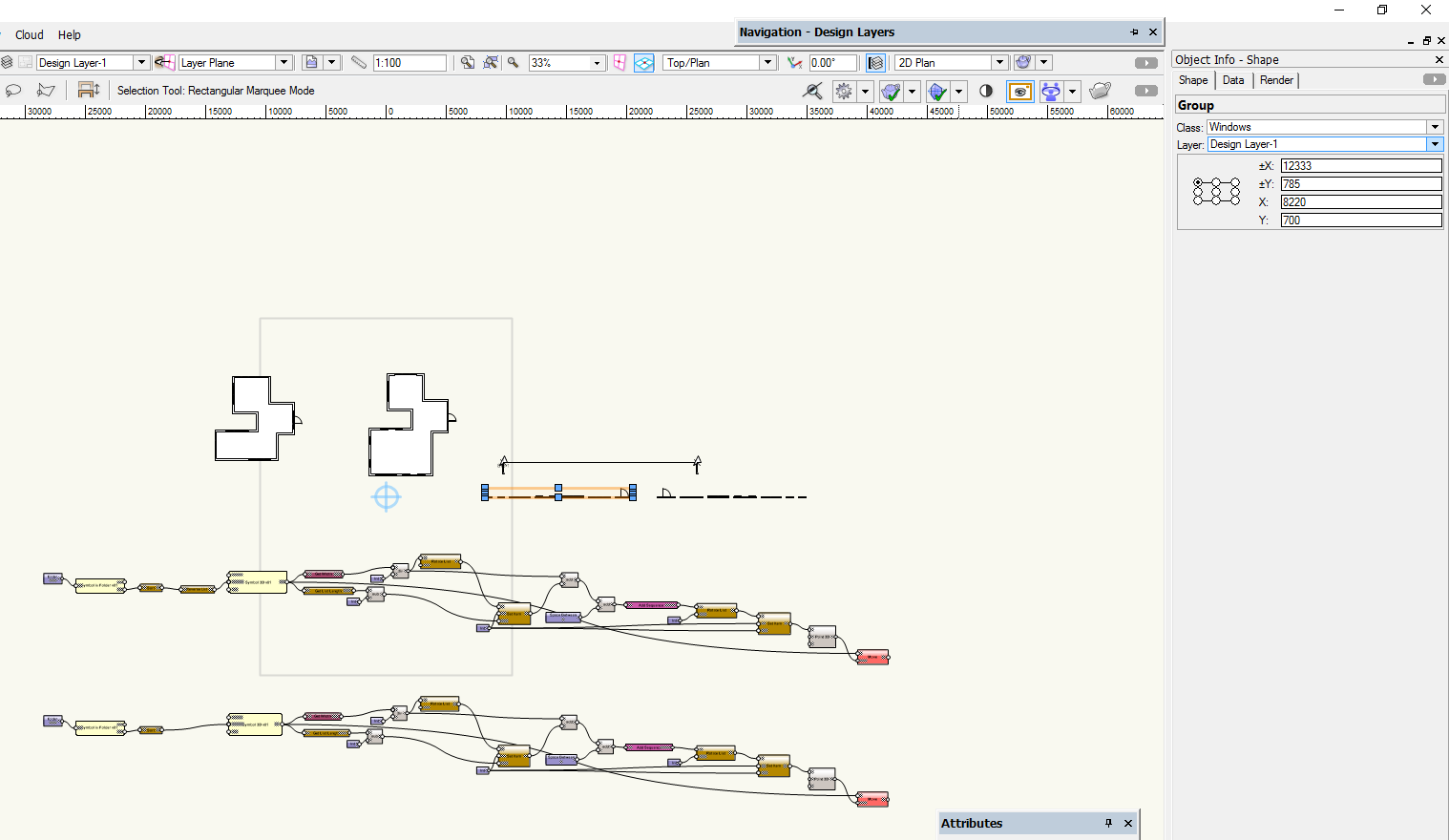
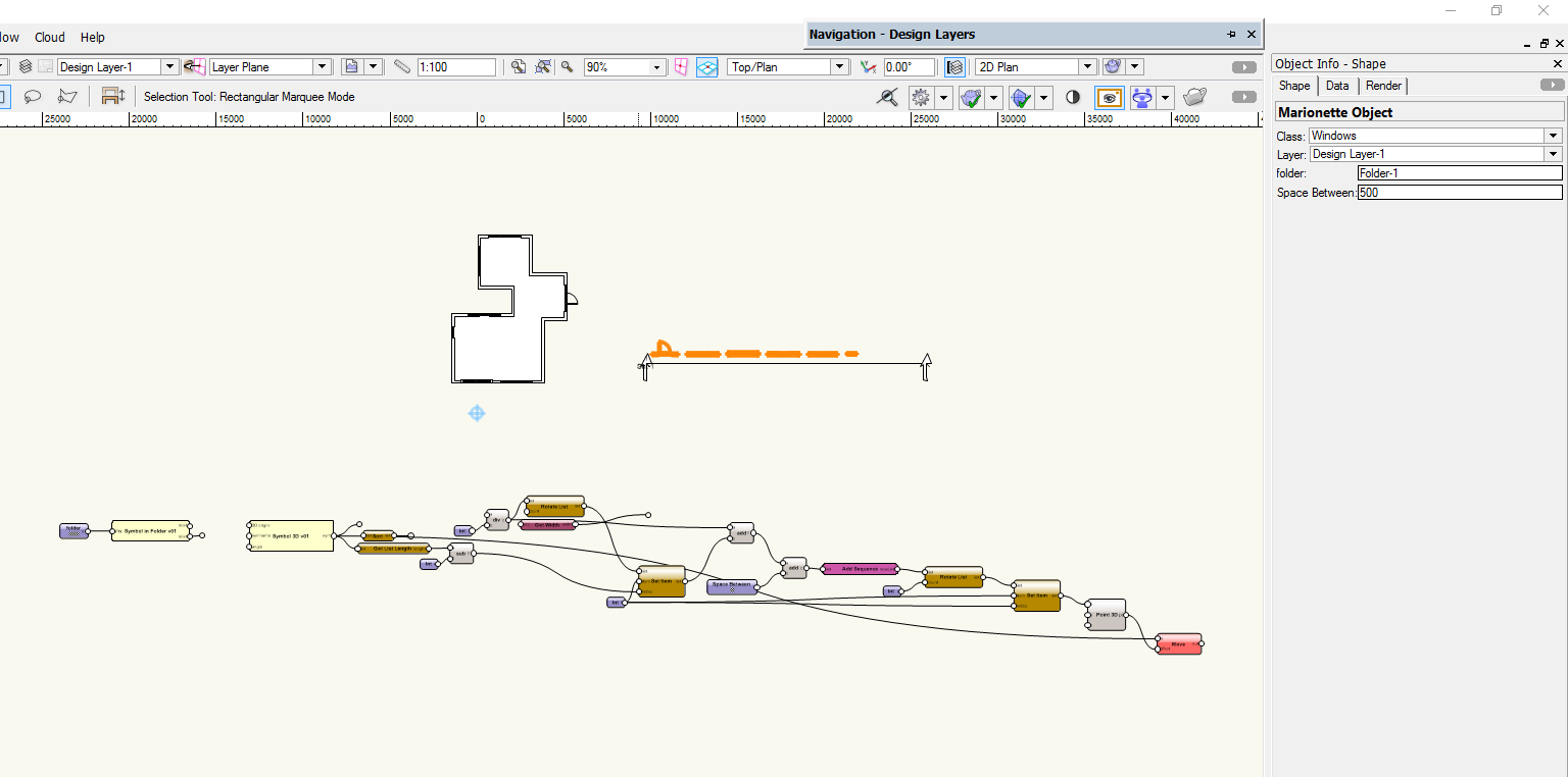
In your schedule 001, there was a marionette string plus a marionette object - & in the OIP you could specify the space between the windows.
In your schedule 002, there are 2 marionette strings, but no marionette object. The windows created are now groups and there isn't the option to specify the distance between.
Can you please just explain the correct way to use this in a different file?
Thank you
Brett
-
Thanks Alan, will try that out.
Attached is a sample schedule.
Cheers Brett
-
Hi Alan, we've had a quick trial with your marionette window schedule & it looks promising - nice work.
Just wondering, we number our windows on the plans in an anti-clockwise direction so that in elevation & on the window schedule they are going from left to right in the correct sequence.
The marionette script places the windows from left to right.
Is there a way an option could be added to place the windows from right to left? So that when the section viewport is created, they appear in the correct order.
Thanks
Brett
-
Thanks Alan, some good tips.
Cheers
-
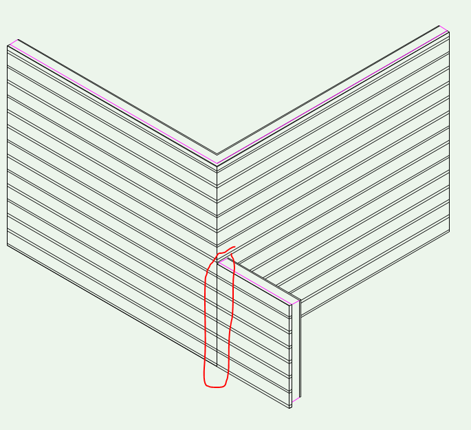
Hi, just wondering how others deal with hiding wall lines showing through hidden line renders at corners where a lower wall butts into a taller wall?
I usually mask these, but it's not always a suitable fix. See image attached.
Thanks
-
This is how we use the Callout/Notes Manager to only have one legend for the whole set of drawings.
After we place the first callout, we move the legend on to a design layer, and then we viewport that legend on to whatever sheet we want to see it on.
The callouts are placed on to design layers and/or sheet layers (in the annotation space). Once we have one callout placed, we just copy and paste it as required and update the callout text from the Database. If we need another Note, we add it on the fly in the Notes Manager.
Note, we use the 'Description' field for numbering the callouts - so they are manually numbered in the format we want.
It's a bit cumbersome, but it works. Ideally, the callouts would be always linked to the database, so if the database changed, the callouts would change too. Sadly it doesn't work this way and once you've placed a callout, it is no longer linked to the database.
-
 2
2
-
-
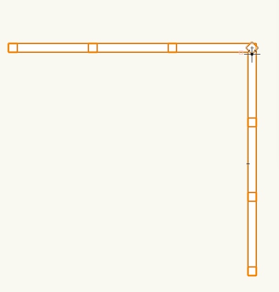
What tool do people use to model balustrades? Tried using the Railing/Fence tool, but encountered some unexpected behaviour.
Corner posts - trying to make the railing go around a 90 degree corner (or any other angle) with a post in the corner doesn't work. The post ends up on an odd angle.
Why can't you use the eyedropper to copy the plugin parameters from one railing to another?
When turning off either the starting post or the ending post or any other combination causes the top rail to 'disappear, or the railing to not show at all. This doesn't seem to happen on all configurations.
My file is attached. Maybe someone can see what setting I have wrong?
Or is there a better tool?
Thanks
-
We have the same issue, any speed improvement on this would be welcome.
-
It's not a huge deal, but with some tools you cannot TAB between fields in the Object Info palette.
Haven't noted exactly which ones are like this, but The Drawing Label & Revision Marker tool's are examples, I'm sure there are others. It's a pain (& slow) having to click with the mouse to enter the next field.
-
This has got our vote for 2018. I think it's been mentioned, but automatically showing the floor level lines on elevations and sections is also a 'basic' function currently missing.
-
2
-
-
We've experienced this too.
-
After using 2017 for a number of weeks now, we are also finding 2017 to be generally slower to work with than 2016 & 2015. For instance, after selecting a 2D line and clicking the line type button in the attribute palette takes 3 seconds for the 'browser' type window to appear so a new line type can be selected. There are random crashes, not too often fortunately, but it's frustrating & time consuming.
-
1
-
-
Hi Mike
What we do to avoid any 3D snapping. With the overlapping roof faces in top/plan view, select the roof faces and use the modify/convert copy to lines command, and choose hidden line as the rendering option. You end up with a group of lines showing the outline of the roof plus the intersecting line between the roof faces. Then you can trim the roof faces to this line. Easy.
-
Hi Tom
This has been asked before and the answer was it can't unfortunately.
We liked the ID option of the framing member tool and also the option to show the member as a single line with end caps, so will continue using the framing member tool until the structural member tool is updated.
-
There are definitely some other issues with the callout tool. In a new VW2017 file, sometimes when adjusting the leader arrow, these weird artifacts appear. (This happens on windows & MAC) See below.
Also, after placing the callout, moving the leader arrow does not snap to angles, so you can't get a vertical leader for example. And in VW2016 you could mirror a callout so that the text was on the other side - not in VW2017.
-
That's disappointing hearing that the bevels and mitres do not transfer through to the IFC model. Let's hope that gets fixed soon. And also the ability to add a text label.
-
I agree with Jonnoxx on the whole story setup, it's so not intuitive currently that we don't bother with it on most projects. With regards to Architecture, we would also like to see a lot more automation happening, eg automatically showing floor levels with datum markers on elevations & sections. Automatically showing grid lines on elevations & sections. Automatically generating window & door schedules in a graphical way rather than a worksheet. All of the information is there, so it would be nice to get the program to do some of this 'donkey' work, so we don't have to manually do it.
-
2
-
-
Can anyone confirm if this is possible please? Also, how do you show the structural member as a single line - like you could with the framing member? Thanks
-
Hi Josh, we have the same issue, and we're still using 2016. I ended up putting the ID's on each side of the building on their own class so that you can turn the ones you don't want to see off.
-
From our experience, it doesn't work like that. Once the callout is placed using the text from the database, it is no longer linked to the database. If you change the callout note on the drawing, you have to then, click the update button so that it updates the database to match the new callout note. It's a very manual process. Tom, you shouldn't have to do any 'finding' of callouts, if you change one callout note/number, then it does change all the other instances of that callout.
Dimension Text Size
in Troubleshooting
Posted
Hi
We have our dimension standard setup with a text style with text set to 7pt.
When placing dimensions, the size of the text actually placed on the drawing is related to the print scale currently set in the print setup. i.e if the print scale is set to 50% the size of the dimension text placed is 14pt. It varies depending on the current print scale. If it's set to 100% the text placed is at the correct size.
Has anyone come across this issue? Can't understand why it works like this?
Thanks