


BG
-
Posts
382 -
Joined
-
Last visited
Content Type
Profiles
Forums
Events
Articles
Marionette
Store
Posts posted by BG
-
-
Is this still an issue in VW2022?
-
Thanks Ron
We have considered using EAP, that would work, but this isn't that user friendly either and I suspect would take just as long as our current method.
Would be good if there was a tool for this.
Cheers
-
-
On 7/25/2021 at 2:19 AM, Kevin C said:
I would agree. There needs to be a fully comprehensive review of the roof tool.
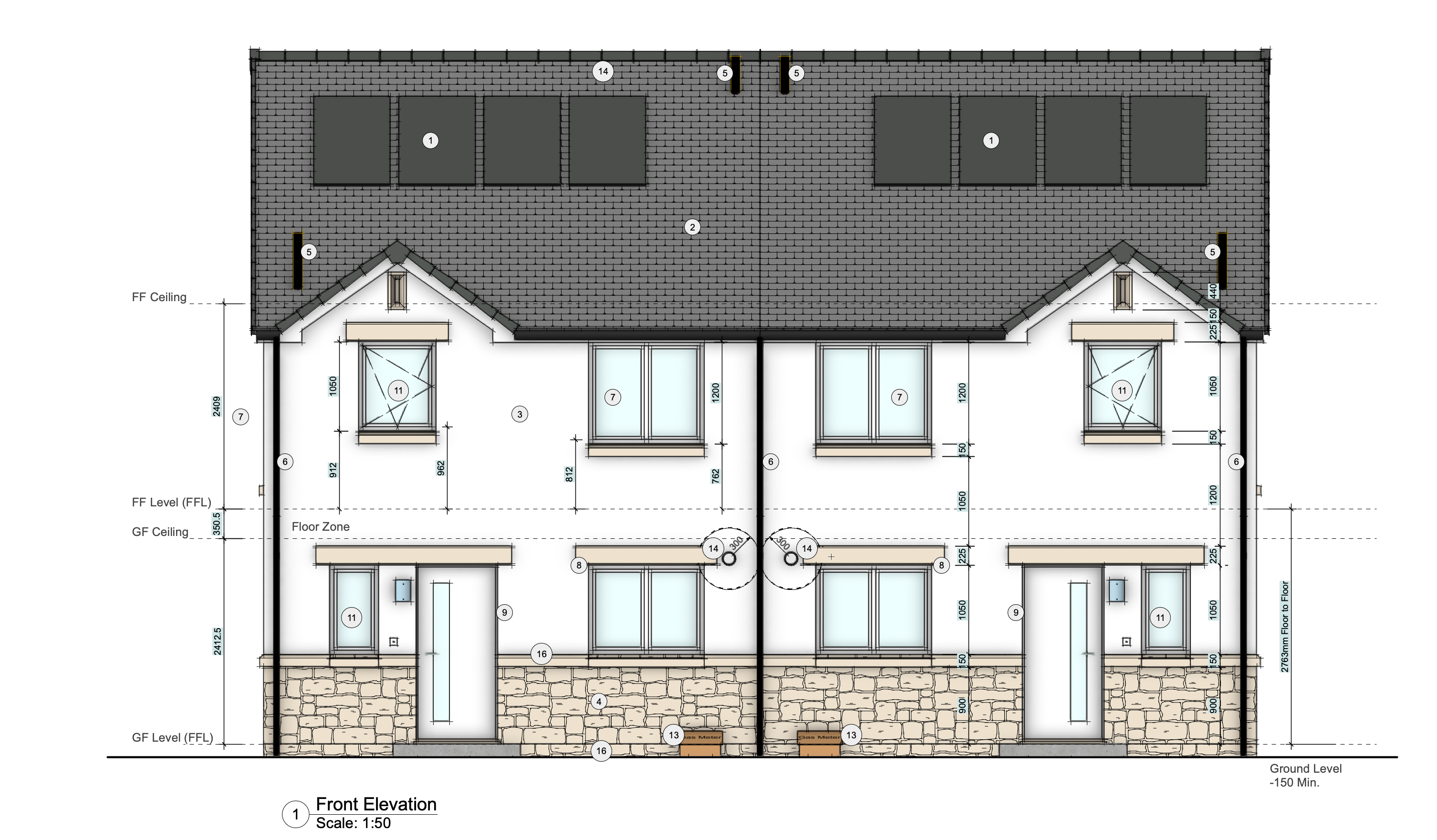
We have just taken on a commission to produce full working and construction drawings for an architect firm and every time I take on a project, it is a school day.
I decided this time that before the 're-worked' plans were issued to the drawing office, that to improve productivity that I would at least try and model as much as I could before the working and construction detail was added.
This is the front elevation of one of the housetypes (NOT MY DESIGN)
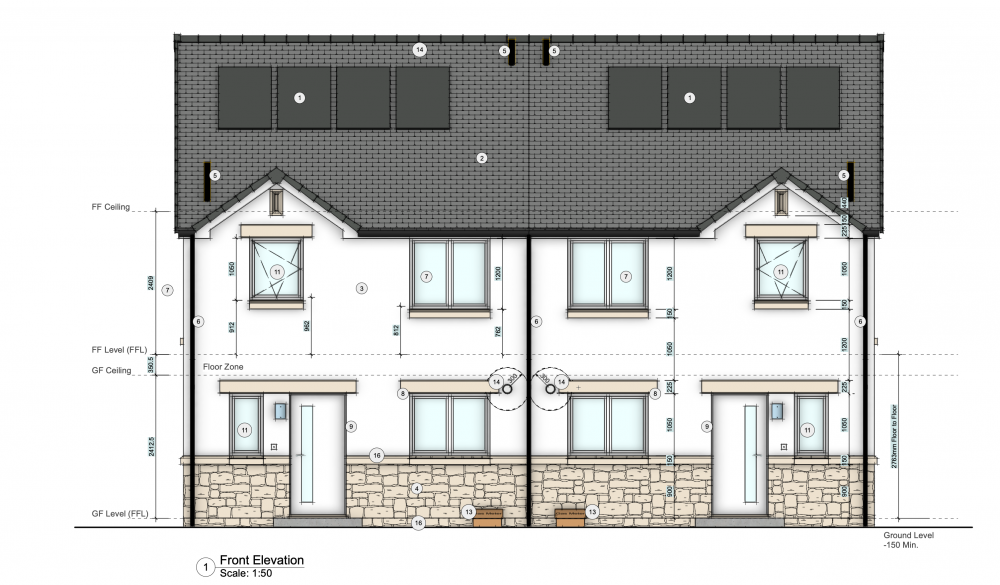
Everything has been modelled with the exception of the annotations and dimensions.
One thing I have now found with the roof is to basically throw away anything with the actual roof tool and multiple components, as VW just cannot deal with anything slightly complicated. Simple features like gable ends cause VW to keel over and die - This is basic stuff. This also allows me to create trusses etc. and they will be accurate.
On the whole, I am really just using roof faces now, with a single component (usually the concrete roof tile and 20mm thick). This allows me to to be accurate in terms of setting out vertically (something again which VW has never been able to do successfully - A roof is set out from the wall head). I can chose the soffit level, facia level etc. based on extrudes, just wish there was more control over how extrudes and solids are displayed in plan views etc.
I can and do have valleys and hips as part of the roof, the ridge-piece above and the gable verge pieces are just a "receptive units" of 3D symbols.
Because all of the doors / windows / features etc. are all objects and symbols, they really just have to be placed in the correct position and VW will do the rest. PS only half of the semi was drawn.
What would make the process much smoother is the be able to store viewport class and layer settings as styles so that they can be used across projects (also being able to edit the style in a worksheet would be a real bonus, can only dream).
On another point. It is disappointing to hear the age old statement 'non-architects'. There are many competent and fully qualified architectural designers / consultants that are more than capable of managing and running projects from conception to completion. As a Chartered Architectural Technologist, one of my practices USP's is that we provide an architectural service from a technical design perspective applied across the whole of the project.
This is great and also how we approach roofs. We don't use a single roof face with components, but model the individual members eg rafters, purlins, roofing, flashings etc. This makes the model accurate and also the elevations and sections don't need too much tidying up in the annotation space, if any.
Would love it if the roof tool could show actual materials like tiles, and include ridge and hip flashings etc. Also the wall tool needs to show cladding/siding materials.
-
 1
1
-
-
Just wondering how others are drawing 3D plumbing schematics? We have been using the HVAC tools, but they aren't overly user friendly. They don't automatically join, the vertical ducts can't be dragged to change their height, there are no falls on the straight ducts etc etc
Any improvement on this would be welcomed.
Thanks
-
Will definitely look into using this technique! Obviously making changes to the wall or roof will require more work to redo the array.
-
Update all might work, but as Pat says, this will update all of the viewports that don't need updating and could take a considerable amount of time, plus it's another step to have to remember to do. Be good if the 'update out of date viewports' worked in embedded viewports too.
Might add a wishlist item.
Thanks
-
I have some design layer section viewports, which are then viewported on to sheet layers. When publishing, even though update out of date viewports is ticked, these design layer section viewports do not get updated and I have to go to the design layer first - update the viewports, then publish.
Is there a way to automatically include these DLSVP's when publishing?
Thanks
-
When typing in the OIP class or layer box, VW starts searching as you type, which is great. I would love the same functionality when typing in other palettes, especially the Navigation Palettes. Having to hit enter/return is slow compared to how the OIP works.
-
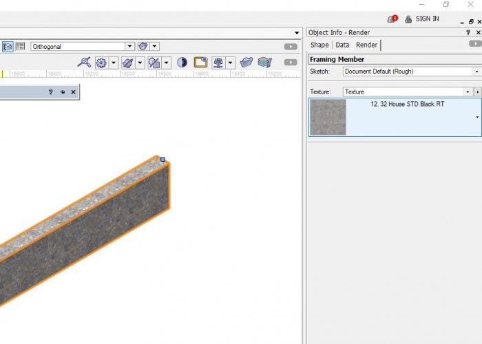
Hi Tom
I just tried adding a texture to a framing member using the render tab, and it seemed to accept a texture fine.
Brett
-
When using the data tag to label space objects on section viewports, only the space objects that the section cuts through should be selectable when using the 'select single object mode'. Space objects beyond the cut plane should not be selectable.
-
2
-
-
For anyone interested, it seems to work better if you give the space object a height & tick the "display 3D" box.
-
1
-
-
I tried that, but it still selects the space beyond the cut plane. To get it to work I temporarily shifted the space beyond so that it wasn't in the same plane as the space I wanted. But this is a hassle and it takes 3 times as long as it should.
-
Hi
Just started using Data Tags with section viewports to name all of the spaces. There are multiple spaces on each floor but what I am finding is the data tag doesn't always pickup the space that the section viewport cuts through, and often selects a space that is beyond - if that makes sense.
When there are multiple space objects how do you go about selecting the correct one?
Thanks
-
19 hours ago, Matt Overton said:
Certainly getting more and more situations in my work I'd like to be able "paint" sections of wall with a slightly different finish that doesn't otherwise effect the wall/structural type to warrant a full wall type.
More and more I'm finding uses for a general sub-style or overlay-style to styled objects that could effect a very limited aspect of an object. Like walls-style to control the all structural aspects of the wall will and Overlay-style applied to part of the wall changes a finish like a panel of different brick.
On most projects we end up using a number of unstyled walls to allow for the odd variation in wall thickness or lining.
When will it be that we can also see the selected cladding or roofing shown in section? eg weatherboard profiles, roofing profiles etc?
-
2
-
-
It's no help sorry, but we experience this issue too. It happens randomly and is pretty annoying.
-
1
-
-
We hope this gets fixed soon too as it is a real pain.
-
Wonder why things like this seemingly simple update take so long to implement? We had to change our section naming convention to suit VW. Not ideal.
-
1
-
-
We discovered your Item 1 straight away & apparently it is a bug (regression) and will be fixed.
Hadn't noticed the changing of colour images to Greyscale, but that could be a nice option to have in the Publish Dialog.
-
7 hours ago, Tom Klaber said:
I do not understand why this is difficult. This drives me nuts -, especially for hatches. It seems to my uneducated mind, that that there could simply be a World Reference Point - a global (0,0,0) that you could set as the origin for the hatch or texture. This should instantly align these from object to object, layer to layer. You could then take it one step further by allowing offset from this 0,0,0. Obviously this is harder than I think - otherwise, we would already have it. I have given up on getting my brick hatches to align from layer to layer - and just look at the ground in embarrassment and shame as I blame my printer when my elevations print....
I often resort to putting a mask over the walls using the extract surface tool to fix up the misaligned textures. This works, but it's a hassle when things change as you have to redo it.
-
2
-
-
- Popular Post
- Popular Post
Also, a big one for us. An improved method for aligning textures on walls, roofs etc.
-
5
-
Are there still Lag Issues with 2020?
-
I might have missed it, but one feature we love about the Framing Member tool is the 'Show ID' option. We can't see that option for the Structural Member tool.
Please can this option be added to the Structural Member tool, then we might start using it.
Thanks
-
- Popular Post
- Popular Post
2021 Wishlist, along with the other items listed above,
The ability to have slanted walls.
Grid lines (and floor level lines) that show up automatically on elevations and sections
-
11

Publish active sheets only
in General Discussion
Posted
When publishing drawings, is there a way to only list sheets that have an 'Active' title block border?
Thanks