domer1322
-
Posts
594 -
Joined
-
Last visited
Content Type
Profiles
Forums
Events
Articles
Marionette
Store
Everything posted by domer1322
-
I've never figured out how to make a normal brick texture. The ones included with VW libraries are based on images that repeat. I want one that shows normal red-brown brick with slight color variations between bricks that don't repeat. Does anyone know what shader settings to use to make a non-repeating brick texture that looks real (or at least close to real) ? I've tried and tried, but I'm beginning to think it is not possible. I'm only a part-time user, but I recall 10 years ago VW could make a non-repeating brick texture, but when they changed the rendering engine several years ago it seems that it isn't possible anymore.
-
thanks .... even though the slab drainage features are not included in VW 2015 your help is appreciated. HOWEVER ... it still doesn't function as I believe it should ... you correctly pointed out that I could add or subtract solids from the slab and shape it the way i wished, but, when I do that, the slab changes into a "solid addition" and loses the characteristics of a slab object. Thus .... I still can't shape a slab object in 3D as I would want to do. If I'm missing something, feel free to let me know. Once again ... thanks for the help ... I did learn something.
-
The video from Matt is nice, but doesn't really solve my initial question. I am convinced there is no way for VW to solve my problem. If you go back and look at my previous posts, you'll see one that shows a 3D image of slab with turned down edges. The slab drainage tool that Matt shows in his video does not allow for the slab to have turned down edges nor changes in slab thickness. In my area, turned down slabs where the edges are thicker, just thick enough to allow the slab to bear below the frost line, are very common. However, it appears there is no easy way for VW to model this. My 3D modeling skills are not good enough to easily this type of geometry (or perhaps VW just won't do this easily). For what it is worth .... I was attempting to draw an entire project (simple garage/shed) entirely in 3D, right down to the bolts). It appears that a designer simply can't do it ..... I seems to me the closest I could expect is to generate sections/details from my 3D model, but always expect that I'll have to alter or fix the 2D image/section to make it accurate. In other words ... a perfect 3D model is simply not possible now .....
-
thanks for sharing .... that tool is better than the VW original. It works nicely in VW 2015.
-
test slab.tiff
-
I'm using VW 2015. This is an academic discussion, because I already made the slab in 3D. However, it was very cumbersome with many steps. Also, when done, my slab can not be edited. If you look at the attached image, you'll see my turned down slab (in 'clip cube' view) and notice how the thickness is not uniform, due to the slopes of the surface. When I used 'screen grab' to make this 2D image, it shows the selection lines, and you can see they indicate the triangles of the different slopes in the surface of the slab. I figure there must be an easier way to do this using solid modeling instead of the way I did it ... I set elevation 3D loci at corners and elsewhere and drew 3D triangles. Extruded each individual triangle, then combined them into a solid. Then subtracted the solid from the "unsloped" slab. This case was simple ... but what if my slab had more complex geometry ? Also .... the concrete would not have 'edges' in it between the triangle slopes, as the conc finisher would be pulling his screed to the center point, then sloping toward the end. test slab.tiff
-
thanks ... I learned a few tips, but ..... that wasn't what I had in mind. I'm trying to exactly model a concrete slab that has very slight slopes (for drainage), so the final answer should be a 3D solid shape. I only mentioned using a DTM because that was the only way I could figure out how to try and model the slab .... although I can't get the final result.
-
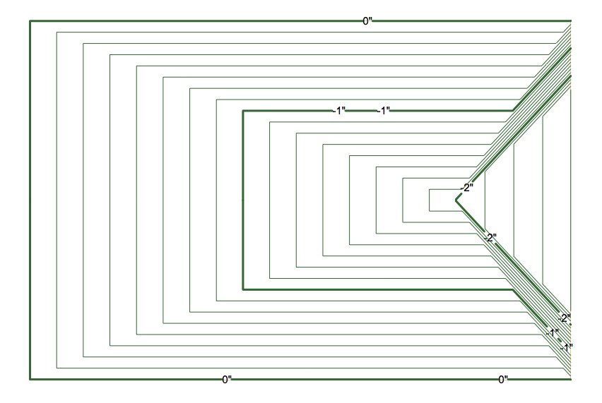
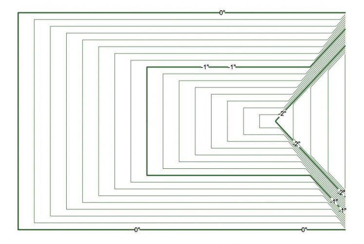
this should be simple for someone who knows what they're doing ..... I want a 3D model with a special slope for a standard concrete garage slab. I can model the slope using a DTM, and the result is shown in the attached image. Since I can't figure out any way to model a 3D solid to show the slope, how can I generate a solid from the DTM with the correct surface slope ? (I'm open to any technique. It doesn't have to use a DTM. Also .. I understand more recent releases of VW have some slope creating features ... but please answer this for a guy like me who has VW 2015.) I've tried many ways to save the 3D model and convert it into a generic solid, but I just can't find a way that works. PS: in the image, don't be alarmed by the contours ... they are set at 1/8" ... it isn't as steep as it looks.
-
Boh: thanks for allowing me to think it isn't all due to my incompetence. I started with trying design layers and had issues so I tried making the garage as a symbol instead. I have a surveyed site plan, and I want the units to show on the survey lines as feet-decimals. However, I also want to make construction drawings of the garage in units "feet-inches". So the survey is on a externally referenced file. If I make the garage a hybrid symbol, then I can make the garage show up as a 2D rectangle on the survey/site plan, without showing the walls/roof/structure on the 2D image. I thought this would allow me to duplicate the garage symbol and make several different versions, all of which could be suitably located by using the "symbol replace" option. Unless someone comes up with a solution that I can understand, I'll guess I will have to try something else. (PS: I'm using VW 2015, so hopefully this "wall in a symbol" issue is fixed on more recent versions.)
-
I can't figure this out .... I have reason to make a small garage into a hybrid symbol. When I insert walls inside (using, copy-paste), as part of the symbol, the height of the wall changes immediately upon pasting. I try to manipulate the heights of various wall components (like the siding) and it does not respond in the same manner as it does when the same wall style type is not part of the symbol. The same behavior occurs when I simply draw the wall using the wall tool while in the "edit symbol" mode. I try to change the wall height in the OIP and by using the wall components in the wall style resource. The height may change, but not in the same way as it does when the wall is not part of the garage symbol. I try using "stories" but I am a novice at using "stories" and I suspect it is operator error/ignorance. Can anyone confirm if the action of placing a wall as part of a hybrid symbol results in unpredictable wall and component height behavior ? .... or ... confirm that i simply don't know what I'm doing.
-
thanks to all of you .... Matt: I read your answer and felt stupid for not seeing that on the OIP ..... until I tried it and found it does not exist in VW 2015. I figured out the best way is to put the survey on a referenced file. Cumbersome .... but I'm glad they fixed it in VW 2018. If I wasn't already retired, maybe I'd upgrade :)
-
Is there a solution for this ..... If I draw a site plan boundary survey on one layer, and the building plan on other layers, there is a conflict with the units displayed. That is, the survey boundary could be shown as feet and inches (like the bldg dimensions) but that is not typical. The common survey uses feet in decimals. That is not common for bldg dimensions. Thus ... is there some method to display feet and inches on some layers, while showing feet in decimals on other layers ?
-
OOps .... sorry .... you were right Markdd. I figured out how to do it ..... it was so easy if you know what to do.
-
thanks ... but ..... I have VW 2015 and when I right click I do not get an option for "extract image". Any other suggestions ?
-
Can the image of a texture that is shown in the thumbnail browser of the resource palette be changed ? I have some brick textures that show the entire image in the resource browser thumbnail, and it is impossible to really see the texture because it is as if you're looking at the bricks from 50 yards away ... everything is too small to see the bricks.
-
If I made a texture using an image from a jpeg file, then I deleted the original jpeg file, is there a way to recover the original image file from the texture ? That is ... I want to make a change to the image file, but the image file is deleted and all that remains is the texture. I understand I could apply the texture to something and make an export of the object, but that seems to have problems with resolution and an inaccurate representation of the original image due to lighting affects. Is there an easy solution ? I figure there must be a "hidden" file of the original image somewhere inside the VW file, but don't know how to find it.
-
just thought I'd add this note to bring this topic to the top of the forum list .... does anyone care ? I really do think that Nemetshek has some responsibility to ensure I can use the product I already paid for .... this is not really an "old software compatibility" problem. This is an activation problem. If I can't activate it over the internet, shouldn't Nemetschek just tell me how to make it run without internet activation ?
-
I found this old thread that is nearly exactly my current problem, so i thought I'd ask again if this problem is solvable. In my case, I have VW2014 and it activates over the internet just fine, and is fully useable. However, VW 2015 does not activate, and shows the same error message as listed above. There was a time when it worked correctly on my 2010 MacBook Air. Then, there was a time when I could click on the "try again" button multiple times and it might work. I think one time I clicked on it about 30 times and it worked. Now I've clicked over 40 times and it doesn't work. Sadly I tried to remove my DNS server number, but the little "minus" check box is grayed and I couldn't remove the DNS server from the preferences. I found that I could add a DNS server, and I put in a dummy number, that made no difference. I don't use VW on the MacBook for anything serious, so this has never been a priority, but I'd still like to solve this problem. Any help ? Jim ?
-
can anyone explain why my custom lines have this behavior ... look at the attached file and you see the left image has the lines as I expect to see them. The left side is rendered in "top / plan" view. Now look at the right image and see the lines sort of extend past the corner in some places. The right image is as it occurs in wireframe or OpenGL or in 'top' view. I tried changing the lines into polylines and individual segments, but nothing seems to work consistantly. line test.tiff
-
Boh: thanks for your help .... your ideas worked. I re-copied the spaces into a new layer and made a brand new worksheet. Success ! Also: thanks for the tip on the OIP data field. I found it and added the Number of occupants on the OIP. That is much easier. However, it appears the space object (in VW2015) does not have two-way capable worksheets for that data field. It has capability for some fields, but not for others ... unless i'm missing something. Once again ... thanks.
-
thanks for your help ..... but ..... I tried adding columns for layer and class, and that told me the 3 "blank" items are on the same layer as the space objects, with "Space-Spec" and "none" for the classes. Then I added the "XCenter" and "Ycenter" columns, and the resulting locations were near my floor plan, but about 50 ft outside of it, in a blank area of the screen. I tried selecting anything in the area, but nothing can be selected in that location (perhaps because there isn't anything there). ALSO: my database criteria was layer=1st floor spaces and type=space. (I put my spaces on a different design layer than the floor plan.) So you taught me a few things (thanks) but I still have the initial problem. Also ... the columns shown on my worksheet are 'area' and 'occupancy'. I am manually entering the occupancy for each space, so the numbers are incomplete/wrong. However ... now that generates another question that you might find easier to answer. I am individually selecting each space object, then clicking on the "settings" button in the OIP to find the occupant number and change it. I recall there is a way to alter the OIP so that it will show an additional data field for something like "occupancy". If done, then I could change the occupancy number directly in the OIP. Can someone point me in the right direction as to how to change the data fields in the OIP ? ( I looked and couldn't figure it out.) I decided to attach a revised screen shot .... maybe that will give a clue ? This file is for my church and I have replicated this file over many years, always translating the file into a newer version of VW. Is it possible that this anomaly is simply the result of an old, re-used file that started in VW 2001 and is now somehow corrupted in ways that are not to be understood ? Is there a solution to that ? spaces test.tiff
-
thanks, but i tried that many times without success. When i did it, the design layer view changes slightly, as if the view is panning to put a selected object in the center of the screen. However, there is no visual selection 'border' around any thing, and the OIP says nothing is selected. I also tried to use the icon that puts all selected objects on the screen, but that doesn't even force the view to pan. Any other ideas ?
-
I don't know worksheets well, and I can't solve this problem: on the attached image you'll see the final three rows of the database are empty on the left side, but seem to have a value in the other columns. I set the search criteria for all space objects on a certain layer, and I'm convinced I have 68 space objects. However, the worksheet shows 71 objects with the last three having odd values. I simply want to delete the last three rows, but I can't. If I try to "delete row" the entire list of 68 objects is deleted. I tried to find the final 3 items on my drawing (database numbers 3.69, 3.70, and 3.71) but I can't find them with all classes turned on. There must be 3 objects with a space record, but I sure can't find them. Can anyone offer some help with this ? I'm using VW 2015. space test.tiff
-
OK ... thanks for the very quick response .......
-
I rendered a fixed window with 4 panes and discovered this oddity. At the location where the glass panes meet the jambs and mullions, the glass pane and the framing members are in the same plane, so the OpenGL render shows the interference patterns that it always shows when two objects share the same plane. In the attached image, I put a red dot near one such occurrence. Is there a way to eliminate this ? test window.tiff